Page 50 of 366
When not using the LATCH system,
all child seats must be secured to the
vehicle with the lap part of a lap/
shoulder belt.With the child seat in the desired
seating position, route the belt
through the child seat according
to the seat maker’s instructions,
then insert the latch plate into the
buckle.To activate the lockable retractor,
slowly pull the shoulder part of the
belt all the way out until it stops,
then let the belt feed back into the
retractor.
Af ter the belt has retracted, tug on
it. If the belt is locked, you will not
be able to pull it out. If you can pull
thebeltout,itisnotlocked,and
you will need to repeat these steps.
In addition, the lap/shoulder belts in
all seating positions except the
driver’s have a locking mechanism
that must be activated to secure a
child seat.
1.2.
3.
CONT INUED
Installing a Child Seat
Installing a Child Seat with a L ap/
Shoulder Belt
Driver and Passenger Saf ety
49
�����—�����—�����y������
��������y���
�(�����������y���������y
Page 51 of 366

Af ter conf irming that the belt is
locked, grab the shoulder part of
the belt near the buckle, and pull
up to remove any slack from the
lap part of the belt. Remember, if
the lap part of the belt is not tight,
the child seat will not be secure.Push and pull the child seat
f orward and f rom side-to-side to
verify that it is secure enough to
stay upright during normal driving
maneuvers. If the child seat is not
secure, unlatch the belt, allow it to
retract f ully, then repeat these
steps.
To remove slack, it may help to
putweightonthechildseat,or
push on the back of the seat while
pulling up on the belt. To deactivate the locking
mechanism and remove a child seat,
unlatch the buckle, unroute the seat
belt, and let the belt f ully retract. Since a tether can provide additional
security to the lap/shoulder belt
installation, we recommend using a
tether whenever one is required or
available. A child seat with a tether can be
installed in any seating position in
the back seat, using the anchorage
points shown above.
4.
5.
Installing a Child Seat
Installing a Child Seat with a
Tether
50
COVER
ANCHOR ANCHORAGE POINTS
�����—�����—�����y������
��������y���
�(�����������y���������y
Page 60 of 366

This section gives inf ormation about
the controls and displays that
contribute to the daily operation of
your vehicle. All the essential
controls are within easy reach............................
Control Locations .60
............................
Instrument Panel .61
..........
Instrument Panel Indicators .62
.............................................
Gauges .68
.............
Multi-Inf ormation Display .69
Controls Near the Steering
.........................................
Wheel .118
Windshield Wipers and .....................................
Washers .119
.........
Turn Signal and Headlights .120
.................................
Fog Lights .121
Automatic Lighting Off .......................................
Feature .121
..............
Daytime Running Lights .121
......
Instrument Panel Brightness .122
............................
Hazard Warning .123
...............
Rear Window Def ogger .123
........
Steering Wheel Adjustment .124
.............................
Keys and Locks .125
......................
Immobilizer System .126
..............................
Ignition Switch .127
....................................
Door Locks .128
................
Childproof Door Locks .129
.....................
Remote Transmitter .130
..............................................
Trunk .135
......
Emergency Trunk Opener .136 ...................
Trunk Main Switch .136
..................................
Seat Heaters .137
...............................................
Seats .138
...........
Power Seat Adjustment .138
.........
Driver’s Lumbar Support .138
........................
Head Restraints .139
.....................
Folding Rear Seat .140
Driving Position Memory ........................................
System .142
...........................................
Mirrors .145
..
Adjusting the Power Mirrors . 146
..............
Power Mirror Heaters . 146
............................
Power Windows .147
.......................................
Moonroof .150
...............................
Parking Brake .151
........................................
Sun Visor .152
................................
Vanity Mirror .152
...............................
Interior Lights .153
.........
Interior Convenience Items . 155
.....................
Beverage Holders .156
........
Accessory Power Sockets . 156
.............
Console Compartment . 157
....................
Sunglasses Holder .158
..................................
Glove Box .158
Instruments and Controls
Inst rument s and Cont rols
59
�����—�����—�����y������
��������y���
�(�����������y���������y
Page 61 of 366
Control L ocations
60
AUDIO SYSTEM
HOOD RELEASE HANDLE AUTOMATIC
TRANSMISSION
MANUAL
TRANSMISSION
PARKING BRAKE LEVER
POWER WINDOW
SWITCHES INSTRUMENT PANEL
MASTER DOOR
LOCK SWITCH MIRROR CONTROL AUTO BUTTON
DRIVING POSITION
MEMORY SYSTEM
CLIMATE CONTROL
SYSTEM
FUEL FILL DOOR RELEASE
HANDLE
Vehicle without navigation system is shown. (P.142)
(P.128)
(P.147)
(P.229) (P.230) (P.151) (P.242) (P.244)
(P.160) (P.170)
(P.
145 )
(P.61)
GAUGES (P.68)
MIRRORS CONTROLS
(P.146)
TRUNK RELEASE LEVER (P.135)
�����—�����—�����y������
��������y���
�(�����������y���������y
Page 62 of 366
�Î
�Î
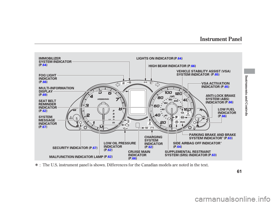
�ΠThe U.S. instrument panel is shown. Dif f erences f or the Canadian models are noted in the text.
:
Instrument Panel
Inst rument s and Cont rols
61
HIGH BEAM INDICATOR
VEHICLE STABILITY ASSIST (VSA)
SYSTEM INDICATOR
VSA ACTIVATION
INDICATOR
MALFUNCTION INDICATOR LAMP
FOG LIGHT
INDICATOR
LIGHTS ON INDICATOR
IMMOBILIZER
SYSTEM INDICATOR
MULTI-INFORMATION
DISPLAY
ANTI-LOCK BRAKE
SYSTEM (ABS)
INDICATOR
LOW FUEL
INDICATOR
CHARGING
SYSTEM
INDICATOR
LOW OIL PRESSURE
INDICATOR
CRUISE MAIN
INDICATOR
SEAT BELT
REMINDER
INDICATOR
SECURITY INDICATOR SUPPLEMENTAL RESTRAINT
SYSTEM (SRS) INDICATORPARKING BRAKE AND BRAKE
SYSTEM INDICATOR
SYSTEM
MESSAGE
INDICATOR (P.64)
(P.66)
(P.69)
(P.62)
(P.67)
(P.67)(P.62)
(P.62) (P.66)(P.62)
(P.64)
(P.63)(P.63)
(P.66)
(P.66)
(P.65)
(P.65)
(P.66)
(P.64)
SIDE AIRBAG OFF INDICATOR
�����—�����—�����y������
��������y���
�(�����������y���������y
Page 65 of 366
 or the LOCK (0) position")
This indicator reminds you that the
exterior lights are on. It comes on
when the light switch is in either theor position. If you turn the
ignition switch to the ACCESSORY
(I) or the LOCK (0) position without
turning of f the light switch, this
indicator will remain on. A reminder
chime will also sound when you open
the driver’s door. This indicator comes on f or a f ew
seconds when you turn the ignition
switch to the ON (II) position. It will
then go of f if you have a properly-
coded ignition key. If it is not a
properly-coded key, the indicator will
blink and the engine will not start
(see page ).
This indicator also blinks several
times when you turn the ignition
switch f rom the ON (II) position to
the ACCESSORY (I) or LOCK (0)
position.
This indicator comes on when you
turn the ignition switch to the ON
(II) position. If it comes on at any
other time, it indicates that the
passenger’s side airbag has
automatically shut of f . You will also
see a ‘‘PASSENGER SIDE AIRBAG
OFF’’ message in the multi-
inf ormation display (see page ).
For more inf ormation, see page .
34 126
81
Side Airbag Of f Indicator
Lights On Indicator
Immobilizer System
Indicator
Instrument Panel Indicators
64
U.S. Canada
�����—�����—�����y������
����
�
�y���
�(�����������y���������y
Page 67 of 366

This indicator comes on with the
high beam headlights. For more
inf ormation, see page .This indicator is in the f uel gauge. It
comesonasareminderthatyou
must ref uel soon. You will also see a
‘‘FUEL LOW’’ message in the multi-
inf ormation display (see page ).
When the indicator comes on, there
is about 2.3 U.S. gal (8.6
)of fuel
remaining in the tank bef ore the
needle reaches E.
This indicator comes on when you
turn on the cruise control system by
pressing the CRUISE button on the
steering wheel (see page ). This indicator comes on when you
turn on the f og lights. For more
inf ormation, see page .
This indicator normally comes on f or
a f ew seconds when you turn the
ignition switch to the ON (II)
position. If this indicator comes on at
any other time, there is a problem in
theABS.If thishappens,takethe
vehicle to your dealer to have it
checked. With this indicator on, your
vehicle still has normal braking
ability but no anti-lock f unction. You
will also see a ‘‘CHECK ABS
SYSTEM’’ message in the multi-
inf ormation display (see page ).
For more inf ormation, see page .
On Canadian models, this indicator
comes on with reduced brightness
when the daytime running lights
(DRL) are on (see page ).
120
204 80
121
82
253 121
Instrument Panel Indicators
High Beam Indicator L ow Fuel Indicator
Fog L ight Indicator
Anti-lock Brake System
(A BS) Indicator
Cruise Main Indicator
66
LOW FUEL INDICATOR
�����—�����—�����y������
��������y���
�(�����������y���������y
Page 70 of 366

position. Some of the messages help
you operate your vehicl")
The multi-inf ormation display in the
instrument panel displays various
inf ormation and messages when the
ignition switch is in the ON (II)
position. Some of the messages help
you operate your vehicle more
comf ortably.
Others help to keep you aware of the
periodic maintenance your vehicle
needs f or continued trouble-f ree
driving.
There are three types of messages;
normal display messages, engine oil
lif e and maintenance messages, and
system messages.
You can also customize some vehicle
control settings to your liking with
the multi-inf ormation display and the
two buttons on the steering wheel
(see page ).When you unlock and open the
driver’s door with the remote
transmitter, the display shows
‘‘Welcome DRIVER 1’’ or ‘‘Welcome
DRIVER 2’’ depending on which
remote transmitter you use. The
driver’s ‘‘ID’’ is detected by the
transmitter. For more information
about driver’s ‘‘ID’’, see page .If you use the key to unlock the
driver’s door, the display only shows
‘‘Welcome.’’ This means the system
cannot recognize either ‘‘DRIVER 1’’
or ‘‘DRIVER 2.’’ In this case, you
cannot use the customize settings in
the multi-information display (see
page ).
When you turn the ignition switch to
the ACCESSORY (I) position, the
display shows ‘‘Goodbye.’’
85
131
85
CONT INUED
Normal Display Messages
Multi-Inf ormation Display
Inst rument s and Cont rols
69
�����—�����—�����y������
��������y���
�(�����������y���������y