Page 1296 of 2893
���
�(�#�'�����������
���������������������"�����)���
���
����
�(�#�'�����������
��������������������� �����)����
16-416-4 Driveline/Axle
Driveshaft Inspection
Driveshaft Removal
F
D B
C
A
E A
B
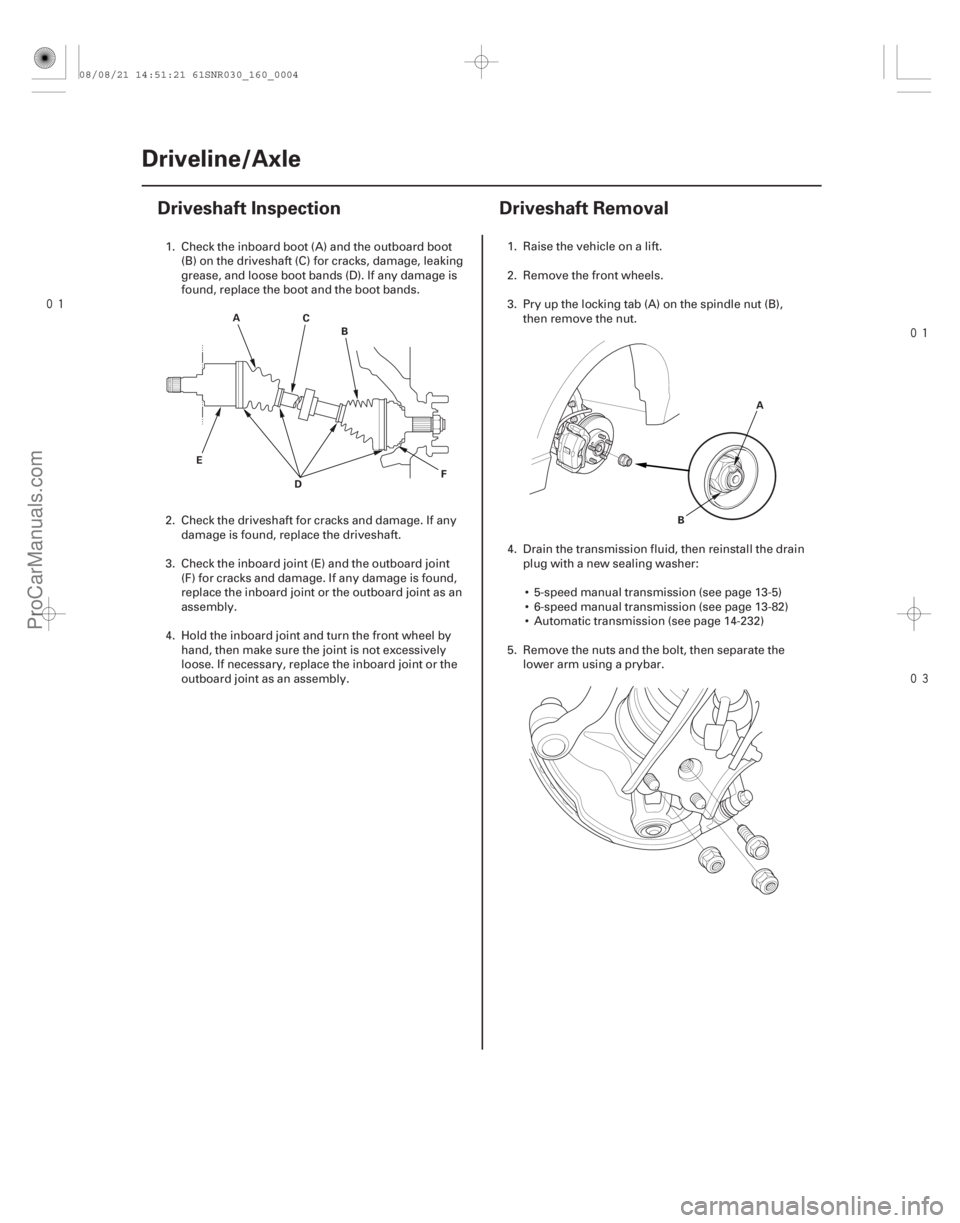
1. Check the inboard boot (A) and the outboard boot (B) on the driveshaft (C) for cracks, damage, leaking
grease, and loose boot bands (D). If any damage is
found, replace the boot and the boot bands.
2. Check the driveshaft for cracks and damage. If any damage is found, replace the driveshaft.
3. Check the inboard joint (E) and the outboard joint (F) for cracks and damage. If any damage is found,
replace the inboard joint or the outboard joint as an
assembly.
4. Hold the inboard joint and turn the front wheel by hand, then make sure the joint is not excessively
loose. If necessary, replace the inboard joint or the
outboard joint as an assembly. 1. Raise the vehicle on a lift.
2. Remove the front wheels.
3. Pry up the locking tab (A) on the spindle nut (B),
then remove the nut.
4. Drain the transmission fluid, then reinstall the drain plug with a new sealing washer:
5-speed manual transmission (see page 13-5)
6-speed manual transmission (see page 13-82)
Automatic transmission (see page 14-232)
5. Remove the nuts and the bolt, then separate the lower arm using a prybar.
08/08/21 14:51:21 61SNR030_160_0004
ProCarManuals.com
DYNOMITE -2009-
Page 1315 of 2893
�����
16-22Driveline/Axle
Driveshaft Installation (cont’d)
B
A
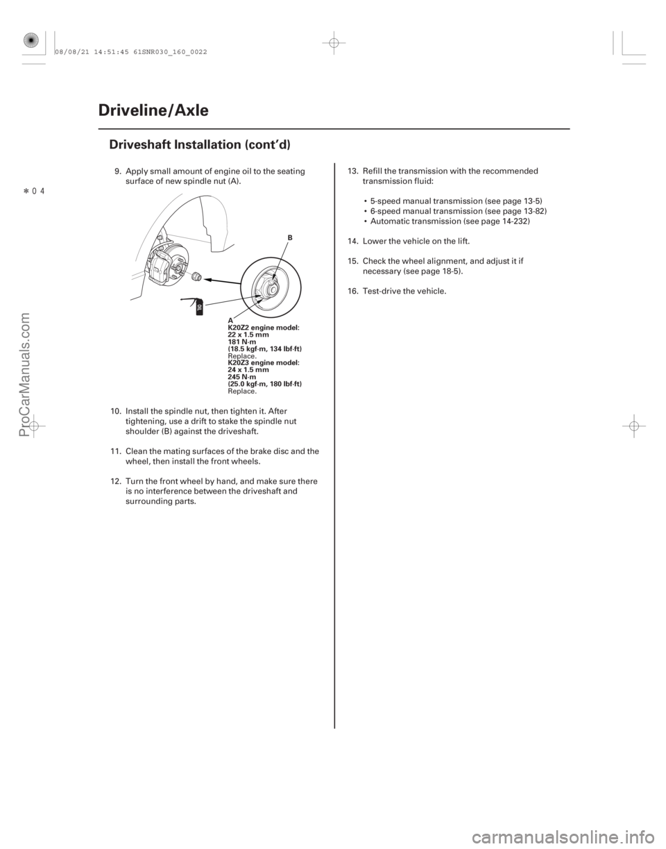
K20Z2 engine model:
22x1.5mm
181 N·m
(18.5 kgf·m, 134 lbf·ft)
K20Z3 engine model:
24x1.5mm
245 N·m
(25.0 kgf·m, 180 lbf·ft)
9. Apply small amount of engine oil to the seating surface of new spindle nut (A).
10. Install the spindle nut, then tighten it. After tightening, use a drift to stake the spindle nut
shoulder (B) against the driveshaft.
11. Clean the mating surfaces of the brake disc and the wheel, then install the front wheels.
12. Turn the front wheel by hand, and make sure there is no interference between the driveshaft and
surrounding parts. 13. Refill the transmission with the recommended
transmission fluid:
5-speed manual transmission (see page 13-5)
6-speed manual transmission (see page 13-82)
Automatic transmission (see page 14-232)
14. Lower the vehicle on the lift.
15. Check the wheel alignment, and adjust it if necessary (see page 18-5).
16. Test-drive the vehicle.
Replace.
Replace.
08/08/21 14:51:45 61SNR030_160_0022
ProCarManuals.com
DYNOMITE -2009-
Page 1316 of 2893
���
��������
�(�#�'�����������
��������������������� �����)����
16-23
Intermediate Shaft Removal
A B A
B
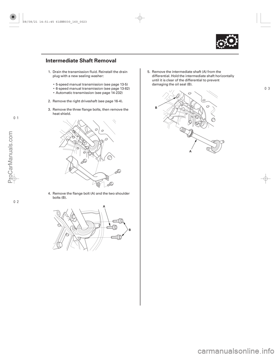
1. Drain the transmission fluid. Reinstall the drain
plug with a new sealing washer:
5-speed manual transmission (see page 13-5)
6-speed manual transmission (see page 13-82)
Automatic transmission (see page 14-232)
2. Remove the right driveshaft (see page 16-4).
3. Remove the three flange bolts, then remove the heat shield.
4. Remove the flange bolt (A) and the two shoulder bolts (B). 5. Remove the intermediate shaft (A) from the
differential. Hold the intermediate shaft horizontally
until it is clear of the differential to prevent
damaging the oil seal (B).
08/08/21 14:51:45 61SNR030_160_0023
ProCarManuals.com
DYNOMITE -2009-
Page 1322 of 2893
����
����
16-28Driveline/Axle
Intermediate Shaft Installation (cont’d)
A
10x1.25mm
39N·m(4.0kgf·m,29lbf·ft)
B
10x1.25mm
39 N·m
(4.0 kgf·m,
29 lbf·ft)
8x1.25mm
22 N·m
(2.2 kgf·m,
16 lbf·ft)
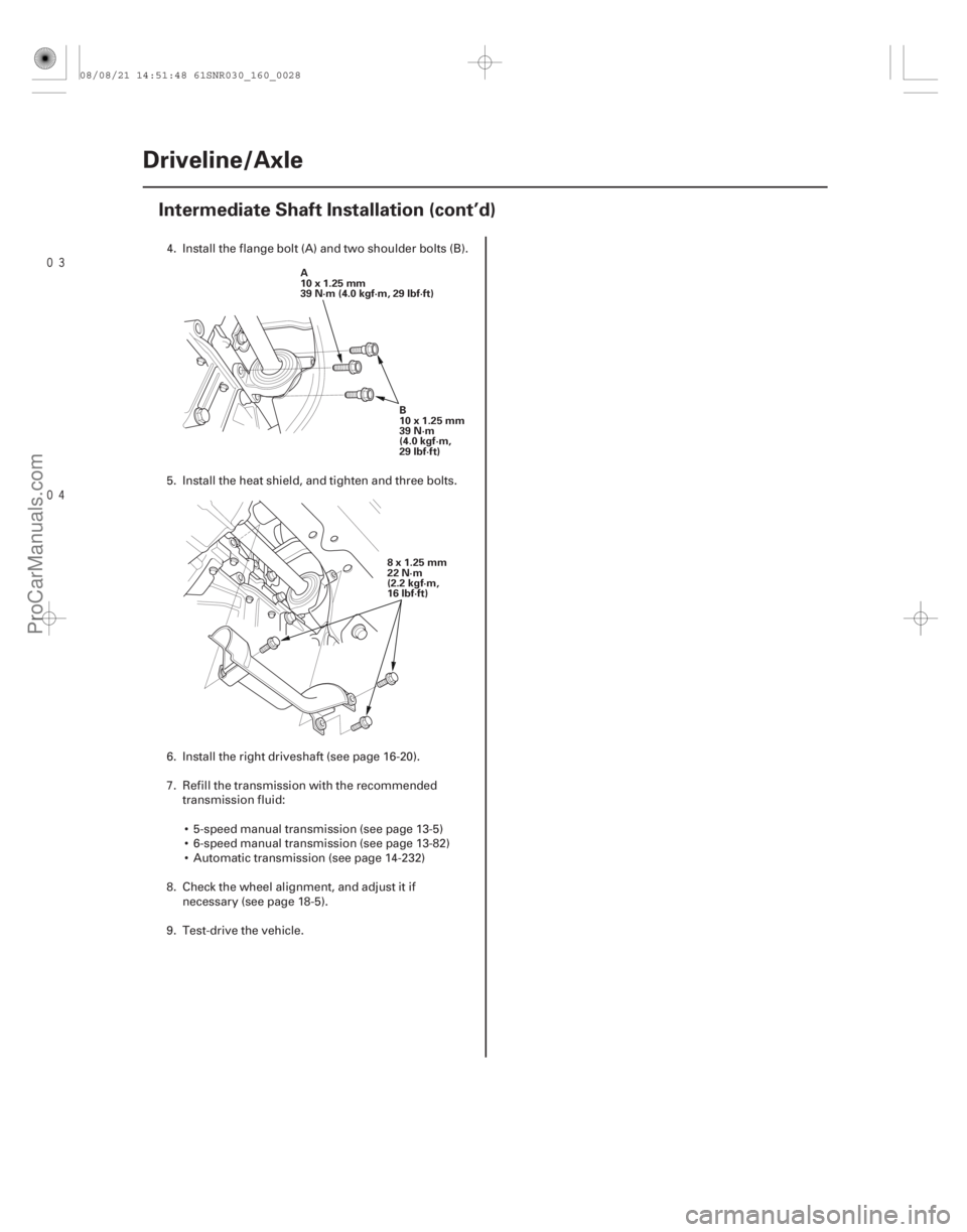
4. Install the flange bolt (A) and two shoulder bolts (B).
5. Install the heat shield, and tighten and three bolts.
6. Install the right driveshaft (see page 16-20).
7. Refill the transmission with the recommended transmission fluid:
5-speed manual transmission (see page 13-5)
6-speed manual transmission (see page 13-82)
Automatic transmission (see page 14-232)
8. Check the wheel alignment, and adjust it if necessary (see page 18-5).
9. Test-drive the vehicle.
08/08/21 14:51:48 61SNR030_160_0028
ProCarManuals.com
DYNOMITE -2009-
Page 1390 of 2893
����
��������
�����
17-67
VSB02C000015
VSB02C000025 B
C
A D
VSB02C000015
AAR-T1256 07MAC-SL0A202
A
B
12 x 1.25 mm 07AAF-SDAA100
D C
AB
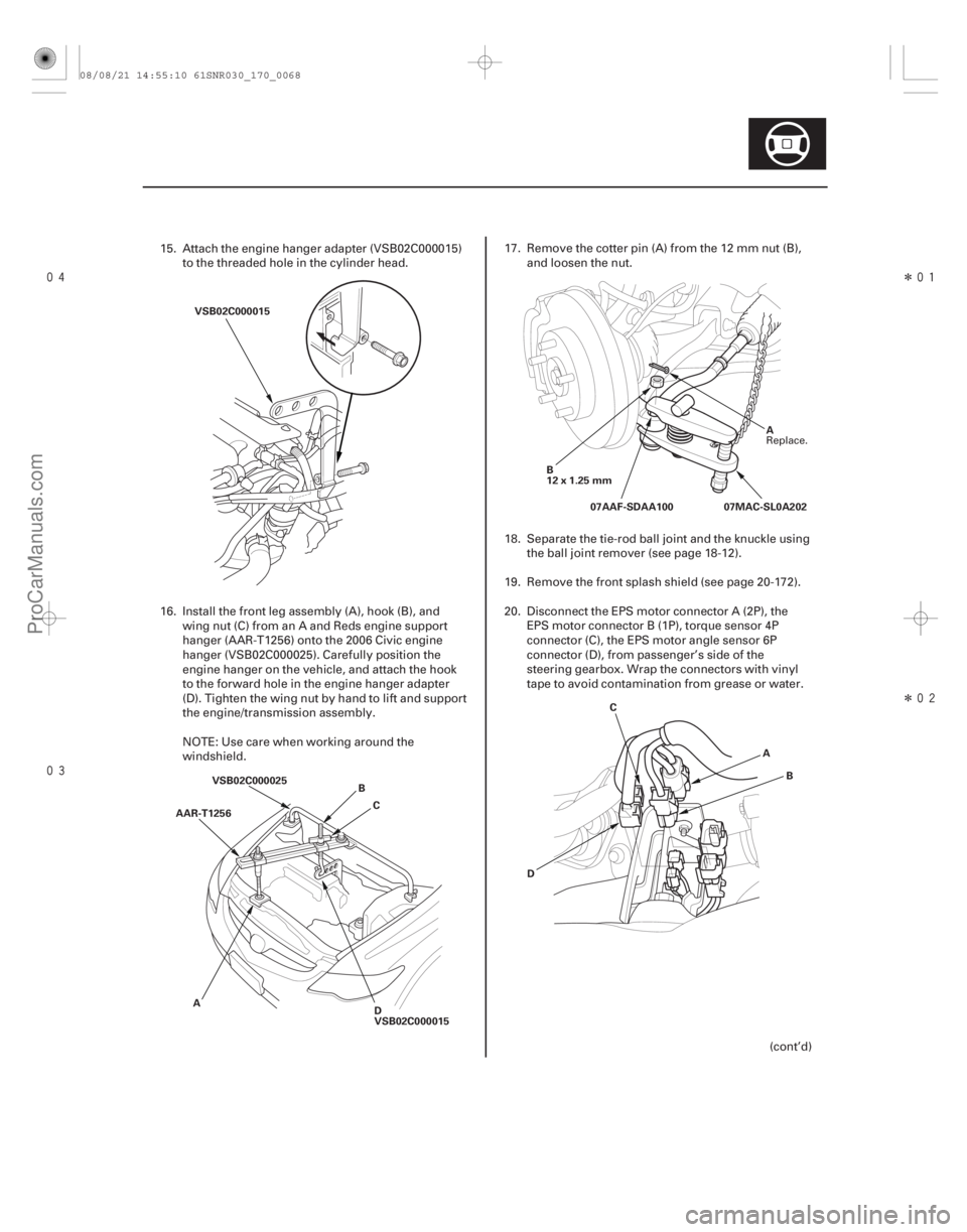
15. Attach the engine hanger adapter (VSB02C000015)to the threaded hole in the cylinder head.
16. Install the front leg assembly (A), hook (B), and wing nut (C) from an A and Reds engine support
hanger (AAR-T1256) onto the 2006 Civic engine
hanger (VSB02C000025). Carefully position the
engine hanger on the vehicle, and attach the hook
to the forward hole in the engine hanger adapter
(D). Tighten the wing nut by hand to lift and support
the engine/transmission assembly.
NOTE: Use care when working around the
windshield. 17. Remove the cotter pin (A) from the 12 mm nut (B),
and loosen the nut.
18. Separate the tie-rod ball joint and the knuckle using the ball joint remover (see page 18-12).
19. Remove the front splash shield (see page 20-172).
20. Disconnect the EPS motor connector A (2P), the EPS motor connector B (1P), torque sensor 4P
connector (C), the EPS motor angle sensor 6P
connector (D), from passenger’s side of the
steering gearbox. Wrap the connectors with vinyl
tape to avoid contamination from grease or water.
(cont’d)
Replace.
08/08/21 14:55:10 61SNR030_170_0068
ProCarManuals.com
DYNOMITE -2009-
Page 1391 of 2893
����
�������
�
��
17-68EPS Components
Steering Gearbox Removal and Installation (cont’d)
A
12x1.25mm
B
12 x 1.25 mm
A BA
BB
A
A
VSB02C000016 B
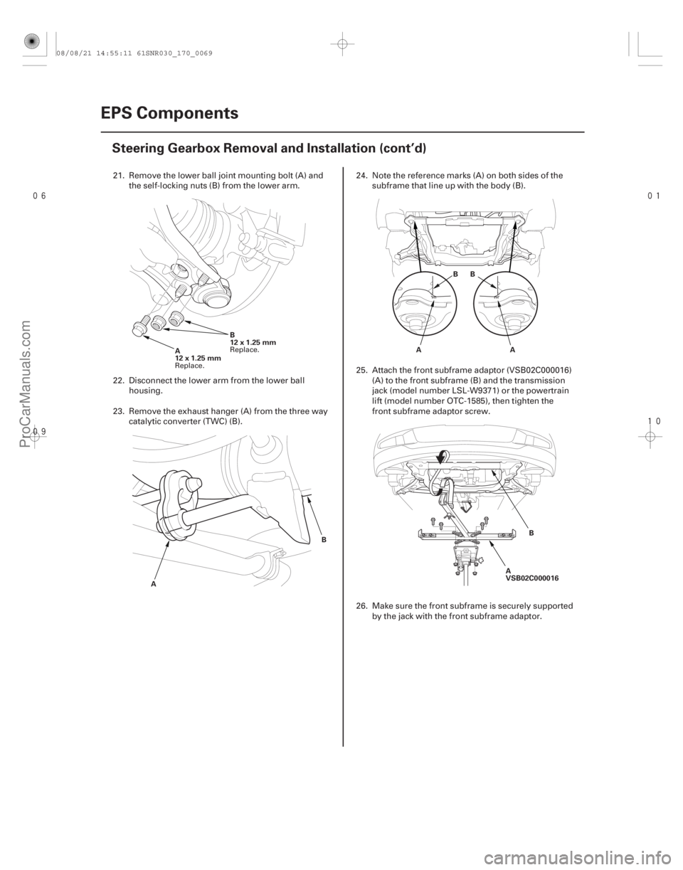
21. Remove the lower ball joint mounting bolt (A) and
the self-locking nuts (B) from the lower arm.
22. Disconnect the lower arm from the lower ball housing.
23. Remove the exhaust hanger (A) from the three way catalytic converter (TWC) (B). 24. Note the reference marks (A) on both sides of the
subframe that line up with the body (B).
25. Attach the front subframe adaptor (VSB02C000016) (A) to the front subframe (B) and the transmission
jack (model number LSL-W9371) or the powertrain
lift (model number OTC-1585), then tighten the
front subframe adaptor screw.
26. Make sure the front subframe is securely supported by the jack with the front subframe adaptor.
Replace. Replace.
08/08/21 14:55:11 61SNR030_170_0069
ProCarManuals.com
DYNOMITE -2009-
Page 1396 of 2893
����
����� ����
����
17-73
A
B
D
C
B
A B
A
6x1.0mm
9.8 N·m
(1.0 kgf·m,
7.2 lbf·ft)
A BB
A
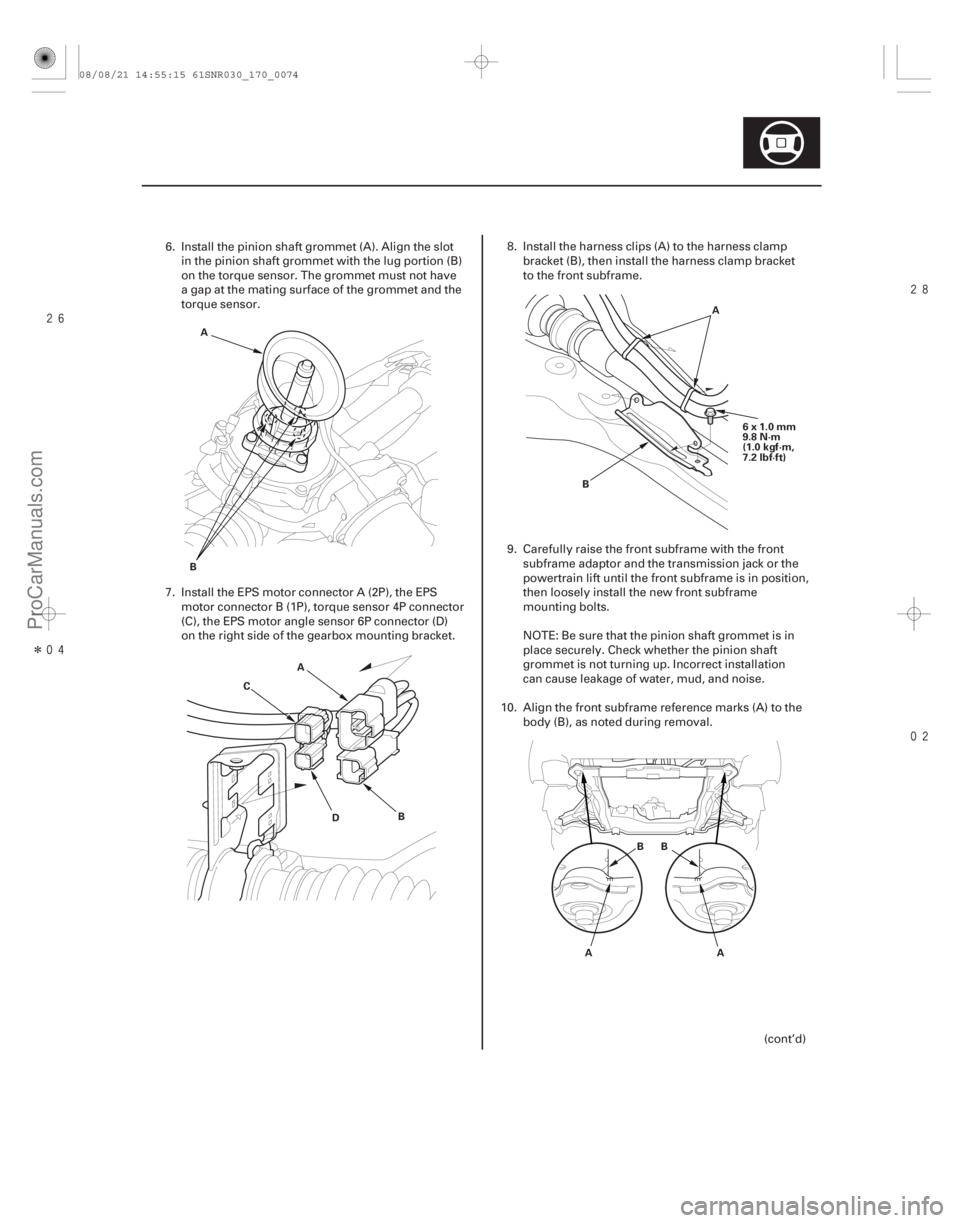
6. Install the pinion shaft grommet (A). Align the slotin the pinion shaft grommet with the lug portion (B)
on the torque sensor. The grommet must not have
a gap at the mating surface of the grommet and the
torque sensor.
7. Install the EPS motor connector A (2P), the EPS motor connector B (1P), torque sensor 4P connector
(C), the EPS motor angle sensor 6P connector (D)
on the right side of the gearbox mounting bracket. 8. Install the harness clips (A) to the harness clamp
bracket (B), then install the harness clamp bracket
to the front subframe.
9. Carefully raise the front subframe with the front subframe adaptor and the transmission jack or the
powertrain lift until the front subframe is in position,
then loosely install the new front subframe
mounting bolts.
NOTE: Be sure that the pinion shaft grommet is in
place securely. Check whether the pinion shaft
grommet is not turning up. Incorrect installation
can cause leakage of water, mud, and noise.
10. Align the front subframe reference marks (A) to the body (B), as noted during removal.
(cont’d)
08/08/21 14:55:15 61SNR030_170_0074
ProCarManuals.com
DYNOMITE -2009-
Page 1398 of 2893
����
��������
����
17-75
A
B
A
14x1.5mm
88 N·m
(9.0 kgf·m,
65 lbf·ft) A
12x1.25mm
64 N·m
(6.5 kgf·m,
47 lbf·ft)
A
12x1.25mm
64 N·m
(6.5 kgf·m,
47 lbf·ft)
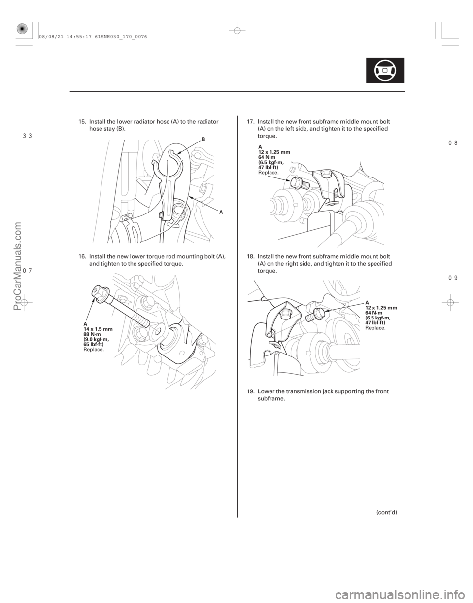
15. Install the lower radiator hose (A) to the radiatorhosestay(B).
16. Install the new lower torque rod mounting bolt (A), and tighten to the specified torque. 17. Install the new front subframe middle mount bolt
(A) on the left side, and tighten it to the specified
torque.
18. Install the new front subframe middle mount bolt (A) on the right side, and tighten it to the specified
torque.
19. Lower the transmission jack supporting the front subframe.
(cont’d)
Replace. Replace.
Replace.
08/08/21 14:55:17 61SNR030_170_0076
ProCarManuals.com
DYNOMITE -2009-