Page 800 of 2893

���
�����(�#�'���������������
�����������
�
�
�"�����)���� ����
����
�(�#�'���������������
���������������
�"�����)����
�µ�µ
�µ�µ �µ�µ
�µ�µ
Standard: 0.20 0.59 mm (0.008 0.023 in.)
Service Limit: 1.3 mm (0.051 in.)
Standard: 13.4 13.7 mm (0.528 0.539 in.) Standard: 0.05 0.25 mm (0.002 0.010 in.)
Service Limit: 0.50 mm (0.020 in.)
Standard: 15.00 15.10 mm (0.591 0.594 in.)
13-2713-27
Reverse Shift Fork Clearance
Inspection
Change Lever Clearance Inspection
B
A
C B
C
A
1. Measure the clearance between the reverse idler
gear (A) and the reverse shift fork (B) with a feeler
gauge (C). If the clearance exceeds the service limit,
go to step 2.
2. Measure the width of the reverse shift fork. If the width is not within the standard, replace thereverse shift fork.
If the width is within the standard, replace the reverse idler gear. 1. Measure the clearance between the change lever
(A) and the select lever (B) with a feeler gauge (C). If
the clearance exceeds the service limit, go to
step 2.
2. Measure the groove width of the change lever. If the groove width is not within the standard,replace the change lever.
If the groove width is within the standard, replace the select lever.
08/08/21 14:45:01 61SNR030_130_0029
ProCarManuals.com
DYNOMITE -2009-
Page 802 of 2893

���
��������
����
�(�#�'���������������
���������������
�"�����)����
�µ�µ
�µ�µ �µ�µ
�µ�µ
Standard: 0.35 0.65 mm (0.014 0.026 in.)
Service Limit: 1.0 mm (0.039 in.)
Standard: 7.4 7.6 mm (0.29 0.30 in.) Standard: 0.2 0.5 mm (0.008 0.020 in.)
Service Limit: 0.62 mm (0.024 in.)
Standard: 16.9 17.0 mm (0.665 0.669 in.)
13-29
Shift Fork Clearance Inspection
A
B
B
A
1. Measure the clearance between each shift fork (A) and its matching synchro sleeve (B). If the
clearance exceeds the service limit, go to step 2.
2. Measure the thickness of the shift fork fingers. If the thickness is not within the standard, replacethe shift fork.
If the thickness is within the standard, replace the synchro sleeve and the synchro hub as a set.
If one arm of the shift fork shows more wear than others, the fork may be bent and needs to be
replaced. 3. Measure the clearance between the shift fork (A)
and the shift arm (B). If the clearance exceeds the
service limit, go to step 4.
4. Measure the width of the shift arm. If the width is not within the standard, replace theshift arm.
If the width is within the standard, replace the shift fork and the reverse shift piece.
08/08/21 14:45:02 61SNR030_130_0031
ProCarManuals.com
DYNOMITE -2009-
Page 873 of 2893

���
�����(�#�'���������������
�����������
�
�
�"�����)���
����
����
�(�#�'���������������
���������������
�"�����)����
�µ�µ
�µ�µ �µ�µ
�µ�µ
Standard: 0.20 0.59 mm (0.008 0.023 in.)
Service Limit: 1.3 mm (0.051 in.)
Standard: 13.4 13.7 mm (0.528 0.539 in.) Standard: 0.05 0.25 mm (0.002 0.010 in.)
Service Limit: 0.50 mm (0.020 in.)
Standard: 15.00 15.10 mm (0.591 0.594 in.)
13-10413-104Manual Transmission
Reverse Shift Fork Clearance
Inspection
Change Lever Clearance Inspection
B
A
C A
B C
1. Measure the clearance between the reverse idler
gear (A) and the reverse shift fork (B) with a feeler
gauge (C). If the clearance exceeds the service limit,
go to step 2.
2. Measure the width of the reverse shift fork. If the width is not within the standard, replace thereverse shift fork.
If the width is within the standard, replace the reverse idler gear. 1. Measure the clearance between the change lever
(A) and the select lever (B) with a feeler gauge (C). If
the clearance exceeds the service limit, go to step
2.
2. Measure the groove width of the change lever. If the groove width is not within the standard,replace the change lever.
If the groove width is within the standard, replace the select lever.
08/08/21 14:47:58 61SNR030_130_0106
ProCarManuals.com
DYNOMITE -2009-
Page 875 of 2893
���
��������
����
�(�#�'���������������
���������������
�"�����)����
�µ�µ
�µ�µ �µ�µ
�µ�µ
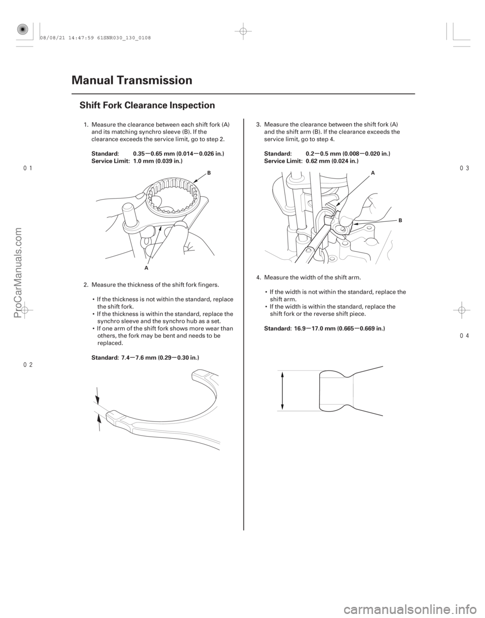
Standard: 0.35 0.65 mm (0.014 0.026 in.)
Service Limit: 1.0 mm (0.039 in.)
Standard: 7.4 7.6 mm (0.29 0.30 in.) Standard: 0.2 0.5 mm (0.008 0.020 in.)
Service Limit: 0.62 mm (0.024 in.)
Standard: 16.9 17.0 mm (0.665 0.669 in.)
13-106Manual Transmission
Shift Fork Clearance Inspection
A
B
A
B
1. Measure the clearance between each shift fork (A)and its matching synchro sleeve (B). If the
clearance exceeds the service limit, go to step 2.
2. Measure the thickness of the shift fork fingers. If the thickness is not within the standard, replacethe shift fork.
If the thickness is within the standard, replace the synchro sleeve and the synchro hub as a set.
If one arm of the shift fork shows more wear than others, the fork may be bent and needs to be
replaced. 3. Measure the clearance between the shift fork (A)
and the shift arm (B). If the clearance exceeds the
service limit, go to step 4.
4. Measure the width of the shift arm. If the width is not within the standard, replace theshift arm.
If the width is within the standard, replace the shift fork or the reverse shift piece.
08/08/21 14:47:59 61SNR030_130_0108
ProCarManuals.com
DYNOMITE -2009-
Page 1182 of 2893
����
����� ����
�µ
�µ�µ
�µ�µ
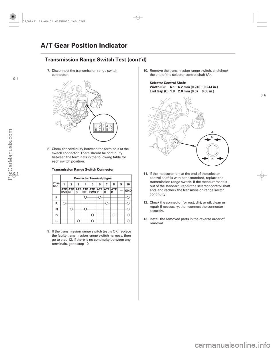
Transmission Range Switch Connector Selector Control Shaft:
Width (B): 6.1 6.2 mm (0.240 0.244 in.)
End Gap (C): 1.8 2.0 mm (0.07 0.08 in.)
14-266A/T Gear Position Indicator
Transmission Range Switch Test (cont’d)
Connector Terminal/Signal
25
134
687910
P
R
N
D
S
Posi-
tion A
C
B
ATP
NP ATP
FWD
GND
ATP
RVS ATP
N ATP
S ATP
PATP
R ATP
D
7. Disconnect the transmission range switch
connector.
8. Check for continuity between the terminals at the switch connector. There should be continuity
between the terminals in the following table for
each switch position.
9. If the transmission range switch test is OK, replace the faulty transmission range switch harness, then
go to step 12. If there is no continuity between any
terminals, go to step 10. 10. Remove the transmission range switch, and check
the end of the selector control shaft (A).
11. If the measurement at the end of the selector control shaft is within the standard, replace the
transmission range switch. If the measurement is
out of the standard, repair the selector control shaft
end, and recheck the transmission range switch
continuity.
12. Check the connector for rust, dirt, or oil, clean or repair if necessary, then connect the connector
securely.
13. Install the removed parts in the reverse order of removal.
08/08/21 14:49:01 61SNR030_140_0268
ProCarManuals.com
DYNOMITE -2009-
Page 1714 of 2893
����
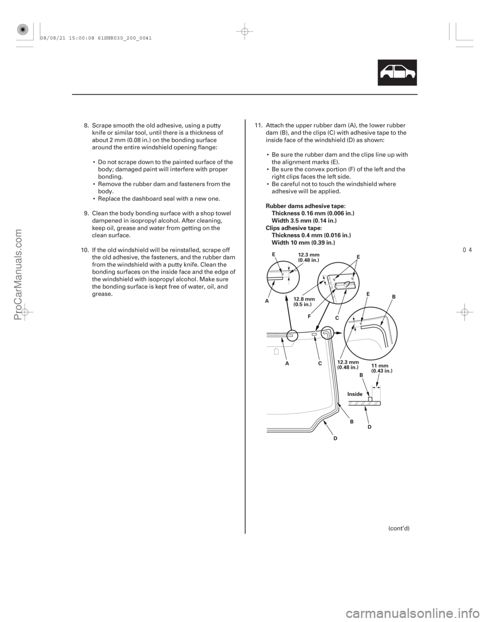
Rubber dams adhesive tape:
Thickness 0.16 mm (0.006 in.)
Width 3.5 mm (0.14 in.)
Clips adhesive tape: Thickness 0.4 mm (0.016 in.)
Width 10 mm (0.39 in.)
20-39
Inside 11 mm
(0.43 in.)
B
D
12.3 mm
(0.48 in.) B
A
CE
E
E
AC B
D
12.3 mm
(0.48 in.)
12.8 mm
(0.5 in.) F
8. Scrape smooth the old adhesive, using a puttyknife or similar tool, until there is a thickness of
about 2 mm (0.08 in.) on the bonding surface
around the entire windshield opening flange:
Do not scrape down to the painted surface of the body; damaged paint will interfere with proper
bonding.
Remove the rubber dam and fasteners from the body.
Replace the dashboard seal with a new one.
9. Clean the body bonding surface with a shop towel dampened in isopropyl alcohol. After cleaning,
keep oil, grease and water from getting on the
clean surface.
10. If the old windshield will be reinstalled, scrape off the old adhesive, the fasteners, and the rubber dam
from the windshield with a putty knife. Clean the
bonding surfaces on the inside face and the edge of
the windshield with isopropyl alcohol. Make sure
the bonding surface is kept free of water, oil, and
grease. 11. Attach the upper rubber dam (A), the lower rubber
dam (B), and the clips (C) with adhesive tape to the
inside face of the windshield (D) as shown:
Be sure the rubber dam and the clips line up with the alignment marks (E).
Be sure the convex portion (F) of the left and the right clips faces the left side.
Be careful not to touch the windshield where adhesive will be applied.
(cont’d)
08/08/21 15:00:08 61SNR030_200_0041
ProCarManuals.com
DYNOMITE -2009-
Page 1715 of 2893
����
��������
����
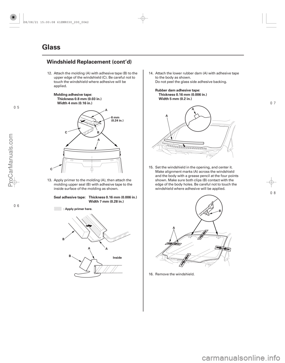
Molding adhesive tape:
Thickness 0.8 mm (0.03 in.)
Width 4 mm (0.16 in.)
Seal adhesive tape: Thickness 0.16 mm (0.006 in.) Width 7 mm (0.28 in.) Rubber dam adhesive tape:
Thickness 0.16 mm (0.006 in.)
Width 5 mm (0.2 in.)
20-40Glass
Windshield Replacement (cont’d)
A
6mm
(0.24 in.)
B
C
C A
: Apply primer here. A
B
Inside
A
B A
A
B
A
12. Attach the molding (A) with adhesive tape (B) to the upper edge of the windshield (C). Be careful not to
touch the windshield where adhesive will be
applied.
13. Apply primer to the molding (A), then attach the molding upper seal (B) with adhesive tape to the
inside surface of the molding as shown. 14. Attach the lower rubber dam (A) with adhesive tape
to the body as shown.
Do not peel the glass side adhesive backing.
15. Set the windshield in the opening, and center it. Make alignment marks (A) across the windshield
and the body with a grease pencil at the four points
shown. Make sure both clips (B) contact with the
edge of the body holes. Be careful not to touch the
windshield where adhesive will be applied.
16. Remove the windshield.
08/08/21 15:00:08 61SNR030_200_0042
ProCarManuals.com
DYNOMITE -2009-
Page 1719 of 2893
��������
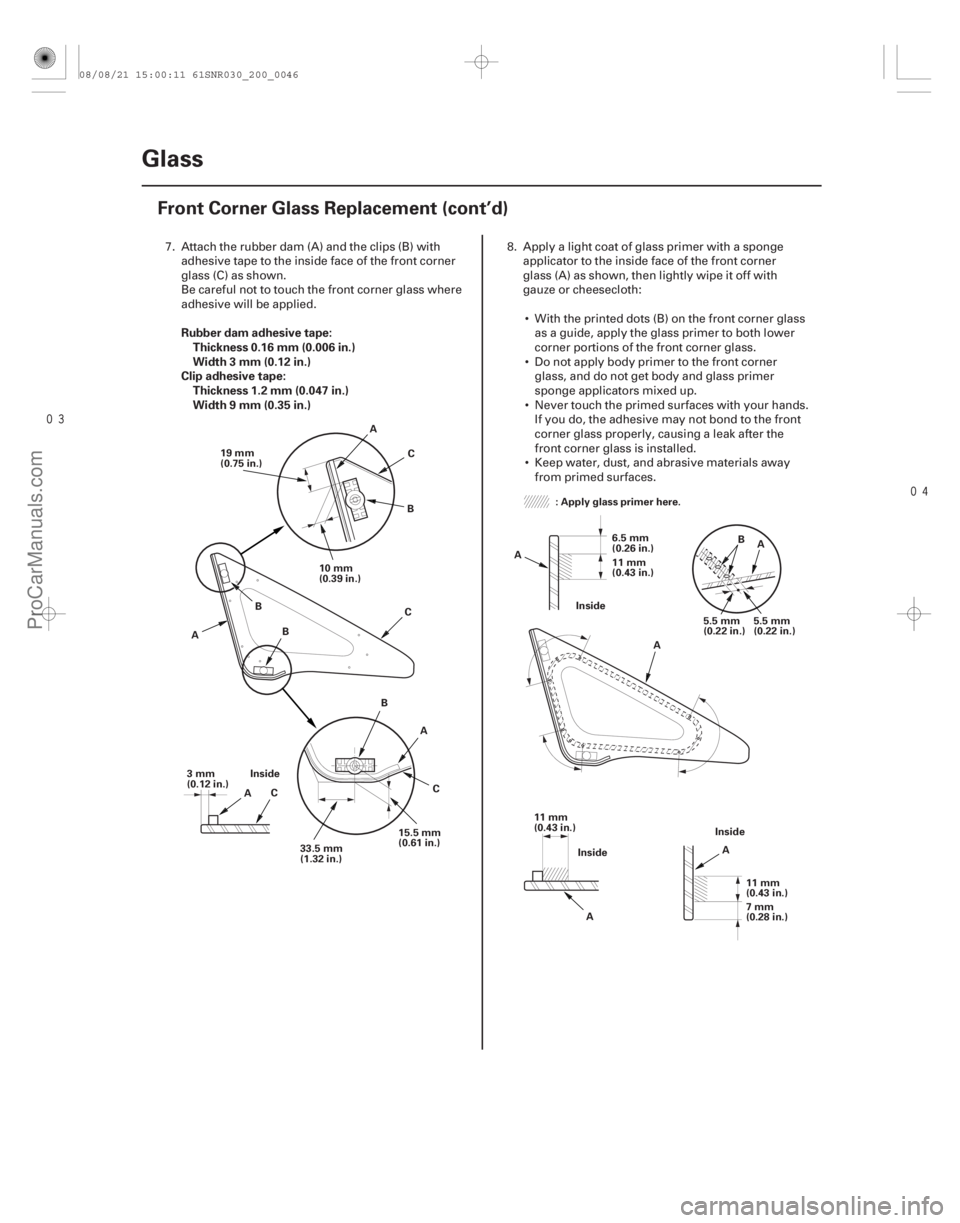
Rubber dam adhesive tape:
Thickness 0.16 mm (0.006 in.)
Width 3 mm (0.12 in.)
Clip adhesive tape: Thickness 1.2 mm (0.047 in.)
Width 9 mm (0.35 in.)
20-44Glass
Front Corner Glass Replacement (cont’d)
33.5 mm
(1.32 in.)
Inside
A C A
BC
19 mm
(0.75 in.)
10 mm
(0.39 in.)
B
B
C
A
15.5 mm
(0.61 in.)
3mm
(0.12 in.)
A
B
C : Apply glass primer here.
Inside 6.5 mm
(0.26 in.)
11 mm
(0.43 in.)
5.5 mm
(0.22 in.)5.5 mm
(0.22 in.)
A
A
A
A B
11 mm
(0.43 in.) 11 mm
(0.43 in.)
A Inside
7mm
(0.28 in.)
Inside
7. Attach the rubber dam (A) and the clips (B) with
adhesive tape to the inside face of the front corner
glass (C) as shown.
Be careful not to touch the front corner glass where
adhesive will be applied. 8. Apply a light coat of glass primer with a sponge
applicator to the inside face of the front corner
glass (A) as shown, then lightly wipe it off with
gauze or cheesecloth:
With the printed dots (B) on the front corner glass as a guide, apply the glass primer to both lower
corner portions of the front corner glass.
Do not apply body primer to the front corner glass, and do not get body and glass primer
sponge applicators mixed up.
Never touch the primed surfaces with your hands. If you do, the adhesive may not bond to the front
corner glass properly, causing a leak after the
front corner glass is installed.
Keep water, dust, and abrasive materials away from primed surfaces.
08/08/21 15:00:11 61SNR030_200_0046
ProCarManuals.com
DYNOMITE -2009-