Page 84 of 646

SPEC
2 - 13
EC212201
CHASSIS
Item Standard Limit
Steering system:
Steering bearing type Taper roller bearing ----
Front suspension: USA, CDN,
AUS, NZ, ZAEUROPE
Front fork travel 300 mm (11.8 in)← ----
Fork spring free length 465 mm (18.3 in)← 460 mm (18.1 in)
Spring rate, STD K = 4.5 N/mm
(0.459 kg/mm,
25.7 lb/in)K = 4.4 N/mm
(0.449 kg/mm,
25.1 lb/in)----
Optional spring/spacer Yes← ----
Oil capacity 445 cm
3
(15.7 Imp oz,
15.0 US oz) 455 cm3
(16.0 Imp oz,
15.4 US oz) ----
Oil grade Suspension oil
“S1”← ----
Inner tube outer diameter 48 mm (1.89 in)← ----
Front fork top end Zero mm (Zero in)← ----
Rear suspension: USA, CDN,
AUS, NZ, ZAEUROPE
Shock absorber travel 132 mm
(5.20 in)← ----
Spring free length 260 mm
(10.24 in)← ----
Fitting length 248 mm
(9.76 in)245 mm
(9.65 in)----
240.5 ~ 258.5 mm
(9.47 ~ 10.18 in)← ----
Spring rate, STD K = 52.0 N/mm
(5.30 kg/mm,
296.8 lb/in)K = 50.0 N/mm
(5.10 kg/mm,
285.6 lb/in)----
Optional spring Yes← ----
Enclosed gas pressure 1,000 kPa
(10 kg/cm
2,
142 psi)← ----
Swingarm:
Swingarm free play limit
End ---- 1.0 mm (0.04 in)
MAINTENANCE SPECIFICATIONS
Page 88 of 646
SPEC
2 - 17
EC212300
ELECTRICAL
Item Standard Limit
Ignition system:
Advancer type Electrical ----
C.D.I.:
Magneto-model (stator)/manufacturer 5XD-00/YAMAHA ----
Source coil 1 resistance (color) 720 ~ 1,080 Ω at 20 °C (68 °F)
(Green – Brown)----
Source coil 2 resistance (color) 44 ~ 66 Ω at 20 °C (68 °F)
(Black – Pink)----
Pickup coil resistance (color) 248 ~ 372 Ω at 20 °C (68 °F)
(White – Red)----
CDI unit-model/manufacturer 5XD-50/YAMAHA (For USA)
5XD-60/YAMAHA (Except for
USA)----
----
Ignition coil:
Model/manufacturer 5TA-10/DENSO ----
Minimum spark gap 6 mm (0.24 in) ----
Primary winding resistance 0.08 ~ 0.10 Ω at 20 °C (68 °F) ----
Secondary winding resistance 4.6 ~ 6.8 kΩ at 20 °C (68 °F) ----
Part to be tightened Thread size Q’tyTightening torque
Nm m·kg ft·lb
Stator M6 × 1.0 3 10 1.0 7.2
Rotor M12 × 1.25 1 56 5.6 40
Neutral switch M5 × 0.8 2 4 0.4 2.9
MAINTENANCE SPECIFICATIONS
Page 103 of 646

2 - 14
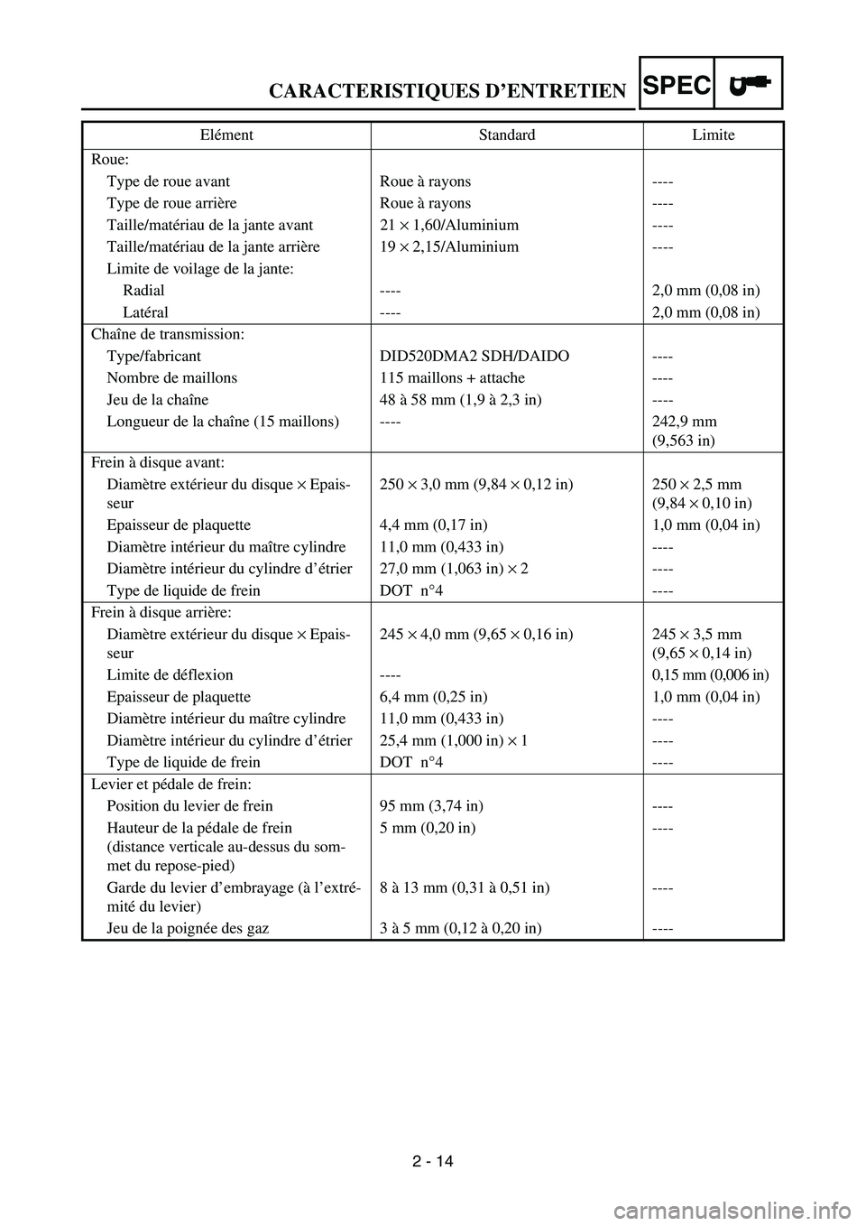
SPECCARACTERISTIQUES D’ENTRETIEN
Roue:
Type de roue avant Roue à rayons ----
Type de roue arrière Roue à rayons ----
Taille/matériau de la jante avant 21 × 1,60/Aluminium ----
Taille/matériau de la jante arrière 19 × 2,15/Aluminium ----
Limite de voilage de la jante:
Radial ---- 2,0 mm (0,08 in)
Latéral ---- 2,0 mm (0,08 in)
Chaîne de transmission:
Type/fabricant DID520DMA2 SDH/DAIDO ----
Nombre de maillons 115 maillons + attache ----
Jeu de la chaîne 48 à 58 mm (1,9 à 2,3 in) ----
Longueur de la chaîne (15 maillons) ---- 242,9 mm
(9,563 in)
Frein à disque avant:
Diamètre extérieur du disque × Epais-
seur250 × 3,0 mm (9,84 × 0,12 in) 250 × 2,5 mm
(9,84 × 0,10 in)
Epaisseur de plaquette 4,4 mm (0,17 in) 1,0 mm (0,04 in)
Diamètre intérieur du maître cylindre 11,0 mm (0,433 in) ----
Diamètre intérieur du cylindre d’étrier 27,0 mm (1,063 in) × 2 ----
Type de liquide de frein DOT n°4 ----
Frein à disque arrière:
Diamètre extérieur du disque × Epais-
seur245 × 4,0 mm (9,65 × 0,16 in) 245 × 3,5 mm
(9,65 × 0,14 in)
Limite de déflexion ---- 0,15 mm (0,006 in)
Epaisseur de plaquette 6,4 mm (0,25 in) 1,0 mm (0,04 in)
Diamètre intérieur du maître cylindre 11,0 mm (0,433 in) ----
Diamètre intérieur du cylindre d’étrier 25,4 mm (1,000 in) × 1 ----
Type de liquide de frein DOT n°4 ----
Levier et pédale de frein:
Position du levier de frein 95 mm (3,74 in) ----
Hauteur de la pédale de frein
(distance verticale au-dessus du som-
met du repose-pied)5 mm (0,20 in) ----
Garde du levier d’embrayage (à l’extré-
mité du levier)8 à 13 mm (0,31 à 0,51 in) ----
Jeu de la poignée des gaz 3 à 5 mm (0,12 à 0,20 in) ---- Elément Standard Limite
Page 126 of 646
2 - 19
SPECLUBRICATION DIAGRAMS
LUBRICATION DIAGRAMS
1Oil delivery pipe
2Intake camshaft
3Exhaust camshaft
4Oil cleaner element
5Oil pump
6Main axle
7Drive axle
7
6
543 2
14
5
A - A
D - D
G
G
D
D A
A
Page 128 of 646
2 - 20
SPECLUBRICATION DIAGRAMS
1Camshaft
2Connecting rod
3Oil cleaner element
4Crankshaft
5Main axle
6Drive axle
7Oil delivery pipe
Page 130 of 646

2 - 21
SPECCABLE ROUTING DIAGRAM
EC240000
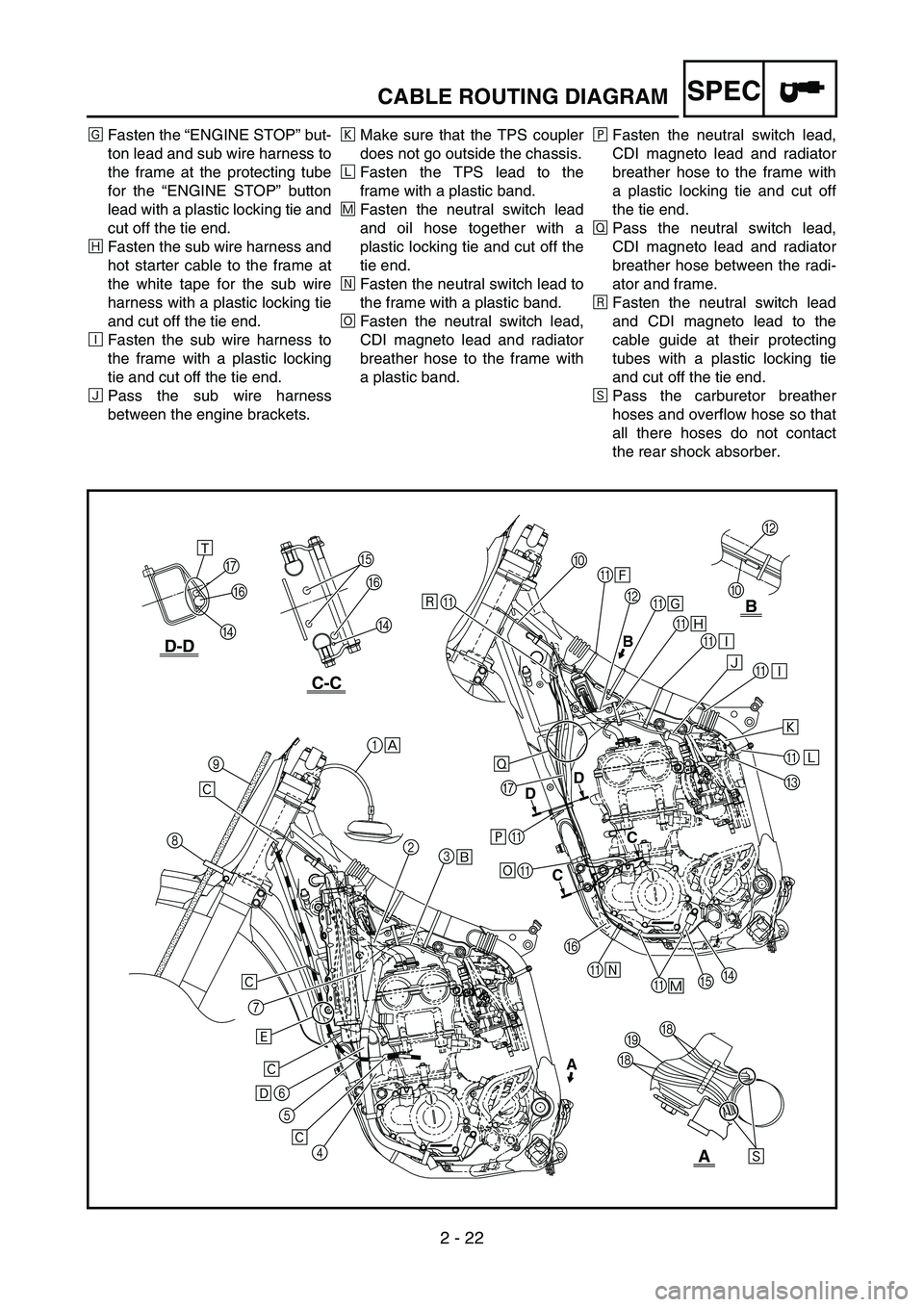
CABLE ROUTING DIAGRAM
1Fuel tank breather hose
2Oil tank breather hose
3Hot starter cable
4Radiator hose 4
5Clutch cable
6Cylinder head breather hose
7Radiator hose 1
8Hose guide
9Brake hose
0“ENGINE STOP” button lead
AClamp
BSub wire harness
CTPS (throttle position sensor)
lead
DNeutral switch lead
EOil hoseFRadiator breather hose
GCDI magneto lead
HCarburetor breather hose
IOverflow hose
ÈInsert the end of the fuel tank
breather hose into the hole in
the steering shaft cap.
ÉPass the hot starter cable
between the cylinder head
breather hose, oil tank breather
hose and ignition coil, then on
the outside of the left engine
bracket.
ÊPass the clutch cable through
the cable guides.ËPass the cylinder head breather
hose on the outside of the radia-
tor hose 1 and on the inside of
the radiator pipe (radiator hose
4).
ÌPass the clutch cable in front of
the lower radiator mounting boss.
ÍFasten the “ENGINE STOP” but-
ton lead and sub wire harness to
the frame at the protecting tube
of the sub wire harness with a
plastic locking tie and cut off the
tie end.
B
0
C-C
D-D
B
A
AB
DD
CC
F
D G
F
D
A
G
A
A
F
AE
A
DC A A A A B A 0
1
2
3
4 5 6 7 89
Ì
Ë
ÊÉ ÈÙÍ
Î
Ï
Ð
Ð Ñ
A
Ô Õ Ø
Ú HIH
E Û
Ò
Ö ×
Ê Ê Ê
Ó
Page 132 of 646

2 - 22
SPECCABLE ROUTING DIAGRAM
ÎFasten the “ENGINE STOP” but-
ton lead and sub wire harness to
the frame at the protecting tube
for the “ENGINE STOP” button
lead with a plastic locking tie and
cut off the tie end.
ÏFasten the sub wire harness and
hot starter cable to the frame at
the white tape for the sub wire
harness with a plastic locking tie
and cut off the tie end.
ÐFasten the sub wire harness to
the frame with a plastic locking
tie and cut off the tie end.
ÑPass the sub wire harness
between the engine brackets.ÒMake sure that the TPS coupler
does not go outside the chassis.
ÓFasten the TPS lead to the
frame with a plastic band.
ÔFasten the neutral switch lead
and oil hose together with a
plastic locking tie and cut off the
tie end.
ÕFasten the neutral switch lead to
the frame with a plastic band.
ÖFasten the neutral switch lead,
CDI magneto lead and radiator
breather hose to the frame with
a plastic band.×Fasten the neutral switch lead,
CDI magneto lead and radiator
breather hose to the frame with
a plastic locking tie and cut off
the tie end.
ØPass the neutral switch lead,
CDI magneto lead and radiator
breather hose between the radi-
ator and frame.
ÙFasten the neutral switch lead
and CDI magneto lead to the
cable guide at their protecting
tubes with a plastic locking tie
and cut off the tie end.
ÚPass the carburetor breather
hoses and overflow hose so that
all there hoses do not contact
the rear shock absorber.
B
0
C-C
D-D
B
A
AB
DD
CC
F
D G
F
D
A
G
A
A
F
AE
A
DC A A A A B A 0
1
2
3
4 5 6 7 89
Ì
Ë
ÊÉ ÈÙÍ
Î
Ï
Ð
Ð Ñ
A
Ô Õ Ø
Ú HIH
E Û
Ò
Ö ×
Ê Ê Ê
Ó
Page 136 of 646

2 - 24
SPECCABLE ROUTING DIAGRAM
1CDI unit
2Hot starter cable
3Throttle cable (return)
4Throttle cable (pull)
5Ignition coil
6Radiator breather hose
7Radiator hose 4
8Cylinder head breather hose
9CDI unit bracket
0CDI unit bandÈPass the hot starter cable and
throttle cables through the cable
guides.
ÉPass the hot starter cable over
the top radiator mounting boss.
ÊPass the hot starter cable and
throttle cables between the radi-
ator and frame, then over the
middle radiator mounting boss.
ËPass the throttle cables on the
outside of the ignition coil.
ÌPass the carburetor breather
hose (throttle cable cover)
through the hose holder.
ÍPass the radiator breather hose
at the rear of the radiator, on the
left of the chassis, and then
between the frame and radiator
hose 4.ÎInsert the CDI unit band over the
CDI unit bracket as far as possi-
ble.
ÏFirst install the CDI unit and CDI
unit band to the CDI unit
bracket, then the CDI unit
bracket to the frame.
8
761
09
12
3
4 ÍB
A
A
B
Î
Ï
É
ÌÈ
Ê
Ë
5