Page 57 of 90

PERIODIC MAINTENANCE AND MINOR REPAIR
6-16
6
EAU21960
Cast wheels To maximize the performance, durabil-
ity, and safe operation of your vehicle,
note the following points regarding the
specified wheels.�
The wheel rims should be checked
for cracks, bends or warpage be-
fore each ride. If any damage is
found, have a Yamaha dealer re-
place the wheel. Do not attempt
even the smallest repair to the
wheel. A deformed or cracked
wheel must be replaced.
�
The wheel should be balanced
whenever either the tire or wheel
has been changed or replaced. An
unbalanced wheel can result in
poor performance, adverse han-
dling characteristics, and a short-
ened tire life.
�
Ride at moderate speeds after
changing a tire since the tire sur-
face must first be “broken in” for it
to develop its optimal characteris-
tics.
EAU22071
Clutch lever free play Since this model is equipped with a hy-
draulic clutch, adjusting the clutch lever
free play is not needed. However, it is
necessary to check the clutch fluid level
and check the hydraulic system for
leakage before each ride. If the clutch
lever free play does become excessive,
and shifting becomes rough or clutch
slippage occurs, causing poor acceler-
ation, there may be air in the clutch sys-
tem. If there is air in the hydraulic
system, have a Yamaha dealer bleed
the system before operating the motor-
cycle.
EAU22290
Rear brake light switch
adjustment The rear brake light switch, which is ac-
tivated by the brake pedal, is properly
adjusted when the brake light comes
on just before braking takes effect. If
necessary, adjust the brake light switch
as follows.
1. Remove panel A. (See page 6-5.)
2. Turn the adjusting nut while hold-
ing the rear brake light switch in
place. To make the brake light
come on earlier, turn the adjusting
nut in direction (a). To make the
brake light come on later, turn the
adjusting nut in direction (b).1. Rear brake light switch
2. Rear brake light switch adjusting nut
U5WME2E0.book Page 16 Tuesday, August 3, 2004 11:40 AM
Page 60 of 90

PERIODIC MAINTENANCE AND MINOR REPAIR
6-19
6significantly lower the boiling point
of the fluid and may result in vapor
lock.
�
Brake fluid may deteriorate paint-
ed surfaces or plastic parts. Al-
ways clean up spilled fluid
immediately.
�
As the brake pads wear, it is nor-
mal for the brake fluid level to grad-
ually go down. However, if the
brake fluid level goes down sud-
denly, have a Yamaha dealer
check the cause.
EAU22750
Changing the brake and
clutch fluids Have a Yamaha dealer change the
brake and clutch fluids at the intervals
specified in the NOTE after the periodic
maintenance and lubrication chart. In
addition, have the oil seals of the brake
and clutch master cylinders and cali-
pers as well as the brake and clutch
hoses replaced at the intervals listed
below or whenever they are damaged
or leaking.�
Oil seals: Replace every two
years.
�
Brake and clutch hoses: Replace
every four years.
EAU22760
Drive chain slack The drive chain slack should be
checked before each ride and adjusted
if necessary.
EAU22791
To check the drive chain slack
1. Place the motorcycle on the cen-
terstand.
2. Shift the transmission into the neu-
tral position.
3. Spin the rear wheel several times
to locate the tightest portion of the
drive chain.
4. Measure the drive chain slack as
shown.1. Drive chain slack
U5WME2E0.book Page 19 Tuesday, August 3, 2004 11:40 AM
Page 61 of 90

PERIODIC MAINTENANCE AND MINOR REPAIR
6-20
6 5. If the drive chain slack is incorrect,
adjust it as follows.
EAU22940
To adjust the drive chain slack
1. Loosen the axle nut and the lock-
nut on each side of the swingarm.
2. To tighten the drive chain, turn the
adjusting bolt on each side of the
swingarm in direction (a). To loos-
en the drive chain, turn the adjust-
ing bolt on each side of the
swingarm in direction (b), and then
push the rear wheel forward.NOTE:Using the alignment marks on each
side of the swingarm, make sure that
both chain pullers are in the same posi-tion for proper wheel alignment.
CAUTION:
ECA10570
Improper drive chain slack will over-
load the engine as well as other vital
parts of the motorcycle and can lead
to chain slippage or breakage. To
prevent this from occurring, keep
the drive chain slack within thespecified limits.
3. Tighten the locknuts, and then
tighten the axle nut to the specified
torque.
Drive chain slack:
20.0–30.0 mm (0.79–1.18 in)
1. Locknut
2. Drive chain slack adjusting bolt
3. Axle nut
4. Alignment marks
Tightening torque:
Axle nut:
150 Nm (15.0 m·kgf, 108 ft·lbf)
U5WME2E0.book Page 20 Tuesday, August 3, 2004 11:40 AM
Page 66 of 90
PERIODIC MAINTENANCE AND MINOR REPAIR
6-25
6
CAUTION:
ECA10590
If any damage is found or the front
fork does not operate smoothly,
have a Yamaha dealer check or re-pair it.
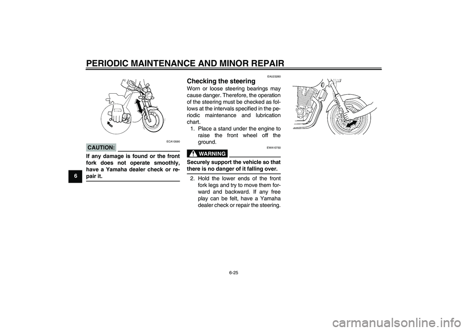
EAU23280
Checking the steering Worn or loose steering bearings may
cause danger. Therefore, the operation
of the steering must be checked as fol-
lows at the intervals specified in the pe-
riodic maintenance and lubrication
chart.
1. Place a stand under the engine to
raise the front wheel off the
ground.
WARNING
EWA10750
Securely support the vehicle so thatthere is no danger of it falling over.
2. Hold the lower ends of the front
fork legs and try to move them for-
ward and backward. If any free
play can be felt, have a Yamaha
dealer check or repair the steering.
U5WME2E0.book Page 25 Tuesday, August 3, 2004 11:40 AM
Page 67 of 90

PERIODIC MAINTENANCE AND MINOR REPAIR
6-26
6
EAU23290
Checking the wheel bearings The front and rear wheel bearings must
be checked at the intervals specified in
the periodic maintenance and lubrica-
tion chart. If there is play in the wheel
hub or if the wheel does not turn
smoothly, have a Yamaha dealer check
the wheel bearings.
EAU33650
Battery This model is equipped with a sealed-
type (MF) battery, which does not re-
quire any maintenance. There is no
need to check the electrolyte or to add
distilled water.
WARNING
EWA10760
�
Electrolyte is poisonous and
dangerous since it contains sul-
furic acid, which causes severe
burns. Avoid any contact with
skin, eyes or clothing and al-
ways shield your eyes whenworking near batteries. In case
of contact, administer the fol-
lowing FIRST AID.
EXTERNAL: Flush with plenty
of water.
INTERNAL: Drink large quan-
tities of water or milk and im-
mediately call a physician.
EYES: Flush with water for 15
minutes and seek prompt
medical attention.
�
Batteries produce explosive hy-
drogen gas. Therefore, keep
sparks, flames, cigarettes, etc.,
away from the battery and pro-
vide sufficient ventilation when
charging it in an enclosed
space.
�
KEEP THIS AND ALL BATTER-
IES OUT OF THE REACH OFCHILDREN.
To charge the battery
Have a Yamaha dealer charge the bat-
tery as soon as possible if it seems to
have discharged. Keep in mind that the
1. Negative battery terminal
2. Positive battery terminal
U5WME2E0.book Page 26 Tuesday, August 3, 2004 11:40 AM
Page 72 of 90

PERIODIC MAINTENANCE AND MINOR REPAIR
6-31
6
EAU33541
Replacing the auxiliary light
bulb If the auxiliary light bulb burns out, re-
place it as follows.
1. Remove the headlight unit by re-
moving the screws.
2. Remove the socket (together with
the bulb) by pulling it out.3. Remove the defective bulb by
pushing it in and turning it counter-
clockwise.
4. Insert a new bulb into the socket,
push it in, and then turn it clock-
wise until it stops.
5. Install the socket (together with the
bulb) by pushing it in.
6. Install the headlight unit by install-
ing the screws.
EAU24360
Front wheel
EAU24470
To remove the front wheel
WARNING
EWA10820
�
It is advisable to have a Yamaha
dealer service the wheel.
�
Securely support the motor-
cycle so that there is no dangerof it falling over.
1. Place the motorcycle on the cen-
terstand.
2. Loosen the front wheel axle pinch
bolt, then the wheel axle and the
brake caliper bolts.
1. Screw
1. Auxiliary light bulb socket
1. Wheel axle
2. Front wheel axle pinch bolt
U5WME2E0.book Page 31 Tuesday, August 3, 2004 11:40 AM
Page 73 of 90

PERIODIC MAINTENANCE AND MINOR REPAIR
6-32
6 3. Remove the brake hose holder on
each side by removing the bolts.
4. Remove the brake caliper on each
side by removing the bolts.
CAUTION:
ECA11050
Do not apply the brake after the
brake calipers have been removed,
otherwise the brake pads will beforced shut.
5. Pull the wheel axle out, and then
remove the wheel.
EAU33660
To install the front wheel
1. Lift the wheel up between the fork
legs.
2. Insert the wheel axle.
3. Install the brake calipers by install-
ing the bolts.NOTE:Make sure that there is enough space
between the brake pads before install-
ing the brake calipers onto the brakediscs.
4. Install the brake hose holders by
installing the bolts.
5. Take the motorcycle off the center-
stand so that the front wheel is on
the ground.
6. Tighten the wheel axle, the front
wheel axle pinch bolt and the
brake caliper bolts to the specified
torques.7. Push down hard on the handlebar
several times to check for proper
fork operation.
1. Brake caliper bolt
2. Brake hose holder
3. Brake caliper
4. Bolt
Tightening torques:
Wheel axle:
72 Nm (7.2 m·kgf, 52 ft·lbf)
Front wheel axle pinch bolt:
20 Nm (2.0 m·kgf, 14 ft·lbf)
Brake caliper bolt:
40 Nm (4.0 m·kgf, 29 ft·lbf)
U5WME2E0.book Page 32 Tuesday, August 3, 2004 11:40 AM
Page 74 of 90

PERIODIC MAINTENANCE AND MINOR REPAIR
6-33
6
EAU25080
Rear wheel
EAU25161
To remove the rear wheel
WARNING
EWA10820
�
It is advisable to have a Yamaha
dealer service the wheel.
�
Securely support the motor-
cycle so that there is no dangerof it falling over.
1. Loosen the axle nut and the brake
caliper bolts.
2. Disconnect the brake torque rod
from the brake caliper bracket by
removing the nut and the bolt.3. Place the motorcycle on the cen-
terstand.
4. Remove the axle nut and the brake
caliper by removing the bolts.
CAUTION:
ECA11300
Do not apply the brake after the
brake caliper has been removed,
otherwise the brake pads will beforced shut.5. Loosen the locknuts, and then turn
the drive chain slack adjusting bolt
on each side of the swingarm fully
in direction (a).
6. Push the wheel forward, and then
remove the drive chain from the
rear sprocket.
NOTE:The drive chain does not need to be
disassembled in order to remove andinstall the rear wheel.
7. While supporting the wheel and
the brake caliper bracket, pull the
wheel axle out.
1. Axle nut
1. Brake caliper bolt
2. Brake torque rod
3. Nut
4. Brake caliper bracket
5. Brake caliper
6. Bolt
1. Wheel axle
2. Drive chain slack adjusting bolt
3. Locknut
U5WME2E0.book Page 33 Tuesday, August 3, 2004 11:40 AM