Page 26 of 610

CHAPTER 3
REGULAR INSPECTION
AND ADJUSTMENTS
MAINTENANCE INTERVALS ...................3-1
PRE-OPERATION INSPECTION
AND MAINTENANCE ................................3-3
ENGINE ......................................................3-4
CHASSIS .................................................3-15
ELECTRICAL ...........................................3-34
CHAPTER 4
ENGINE
SEAT, FUEL TANK
AND SIDE COVERS ..................................4-1
MUFFLER ..................................................4-2
CARBURETOR ..........................................4-3
CYLINDER HEAD ....................................4-12
CAMSHAFT AND ROCKER ARMS ........4-20
VALVES AND VALVE SPRINGS ............4-24
CYLINDER AND PISTON ........................4-32
CLUTCH AND PRIMARY DRIVEN
GEAR .......................................................4-40
OIL PUMP ................................................4-49
KICK AXLE AND SHIFT SHAFT .............4-53
CDI MAGNETO
(TT-R125/TT-R125LW) ............................4-58
CDI MAGNETO AND STARTER
CLUTCH (TT-R125E/TT-R125LWE) .......4-61
ENGINE REMOVAL .................................4-66
CRANKCASE, CRANKSHAFT
AND BALANCER ....................................4-70
TRANSMISSION, SHIFT CAM
AND SHIFT FORK ...................................4-78
Page 81 of 610

SPEC
2 - 8
MAINTENANCE SPECIFICATIONS
Cam chain:
Cam chain type/No. of links DID25SD DHA/88 ----
Cam chain adjustment method Automatic ----
Rocker arm/rocker arm shaft:
Shaft outside diameter 9.981 ~ 9.991 mm
(0.3930 ~ 0.3933 in)9.95 mm
(0.3917 in)
Rocker arm inside diameter 10.000 ~ 10.015 mm
(0.3937 ~ 0.3943 in)10.03 mm
(0.3949 in)
Valve, valve seat, valve guide:
Valve clearance (cold) IN 0.08 ~ 0.12 mm
(0.0031 ~ 0.0047 in)----
EX 0.10 ~ 0.14 mm
(0.0039 ~ 0.0055 in)----
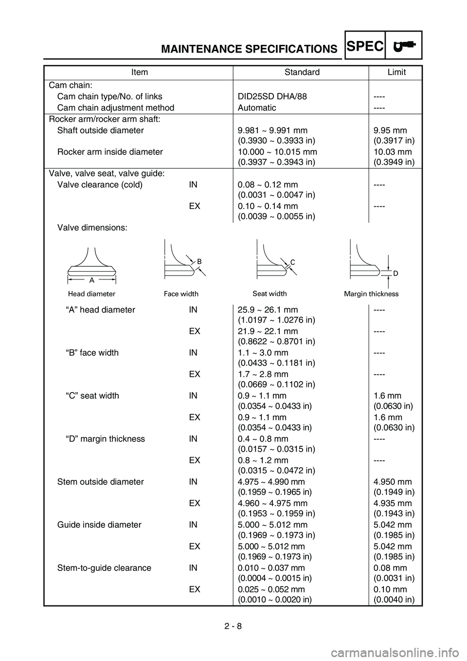
Valve dimensions:
“A” head diameter IN 25.9 ~ 26.1 mm
(1.0197 ~ 1.0276 in)----
EX 21.9 ~ 22.1 mm
(0.8622 ~ 0.8701 in)----
“B” face width IN 1.1 ~ 3.0 mm
(0.0433 ~ 0.1181 in)----
EX 1.7 ~ 2.8 mm
(0.0669 ~ 0.1102 in)----
“C” seat width IN0.9 ~ 1.1 mm
(0.0354 ~ 0.0433 in)1.6 mm
(0.0630 in)
EX 0.9 ~ 1.1 mm
(0.0354 ~ 0.0433 in)1.6 mm
(0.0630 in)
“D” margin thickness IN 0.4 ~ 0.8 mm
(0.0157 ~ 0.0315 in)----
EX 0.8 ~ 1.2 mm
(0.0315 ~ 0.0472 in)----
Stem outside diameter IN4.975 ~ 4.990 mm
(0.1959 ~ 0.1965 in)4.950 mm
(0.1949 in)
EX 4.960 ~ 4.975 mm
(0.1953 ~ 0.1959 in)4.935 mm
(0.1943 in)
Guide inside diameter IN 5.000 ~ 5.012 mm
(0.1969 ~ 0.1973 in)5.042 mm
(0.1985 in)
EX 5.000 ~ 5.012 mm
(0.1969 ~ 0.1973 in)5.042 mm
(0.1985 in)
Stem-to-guide clearance IN0.010 ~ 0.037 mm
(0.0004 ~ 0.0015 in)0.08 mm
(0.0031 in)
EX 0.025 ~ 0.052 mm
(0.0010 ~ 0.0020 in)0.10 mm
(0.0040 in) Item Standard Limit
Head diameter
B
Face widthC
Seat width
D
Margin thicknessA
Page 192 of 610

3 - 10
INSP
ADJOIL PRESSURE INSPECTION/PILOT AIR SCREW
ADJUSTMENT/ENGINE IDLING SPEED ADJUSTMENT
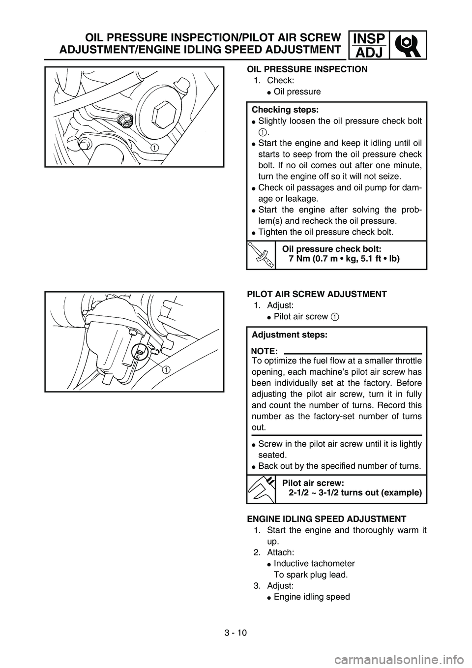
OIL PRESSURE INSPECTION
1. Check:
�Oil pressure
Checking steps:
�Slightly loosen the oil pressure check bolt
1.
�Start the engine and keep it idling until oil
starts to seep from the oil pressure check
bolt. If no oil comes out after one minute,
turn the engine off so it will not seize.
�Check oil passages and oil pump for dam-
age or leakage.
�Start the engine after solving the prob-
lem(s) and recheck the oil pressure.
�Tighten the oil pressure check bolt.
T R..
Oil pressure check bolt:
7 Nm (0.7 m • kg, 5.1 ft • lb)
PILOT AIR SCREW ADJUSTMENT
1. Adjust:
�Pilot air screw 1
Adjustment steps:
NOTE:
To optimize the fuel flow at a smaller throttle
opening, each machine’s pilot air screw has
been individually set at the factory. Before
adjusting the pilot air screw, turn it in fully
and count the number of turns. Record this
number as the factory-set number of turns
out.
�Screw in the pilot air screw until it is lightly
seated.
�Back out by the specified number of turns.
Pilot air screw:
2-1/2 ~ 3-1/2 turns out (example)
ENGINE IDLING SPEED ADJUSTMENT
1. Start the engine and thoroughly warm it
up.
2. Attach:
�Inductive tachometer
To spark plug lead.
3. Adjust:
�Engine idling speed
Page 194 of 610
3 - 11
INSP
ADJ
VALVE CLEARANCE INSPECTION AND ADJUSTMENT
VALVE CLEARANCE INSPECTION AND
ADJUSTMENT
NOTE:
�The valve clearance should be adjusted
when the engine is cool to the touch.
�The piston must be at Top Dead Center
(T.D.C.) on compression stroke to check or
adjust the valve clearance.
1. Remove:
�Seat
�Fuel tank
Refer to “SEAT, FUEL TANK AND SIDE
COVERS” section in the CHAPTER 4. Adjustment steps:
�Adjust the pilot air screw.
Refer to “PILOT AIR SCREW ADJUST-
MENT” section.
�Turn the throttle stop screw 1 until the
specified engine idling speed.
To increase idling speed →
Turn the throttle stop screw 1 in a.
To decrease idling speed →
Turn the throttle stop screw 1 out b.
Inductive tachometer:
YU-8036-B/90890-03113
Engine idling speed:
1,300 ~ 1,500 r/min
2. Remove:
�Spark plug
�Intake tappet cover 1
�Exhaust tappet cover 2
�O-ring
3. Remove:
�Timing mark accessing screw 1
�Crankshaft end accessing screw 2
�O-ring
Page 198 of 610
3 - 13
INSP
ADJ
VALVE CLEARANCE INSPECTION AND ADJUSTMENT
�Measure the valve clearance.
�If the clearance is incorrect, repeat above
steps until specified clearance is obtained.
6. Install:
�O-ring 1
�Crankshaft end accessing screw 2
�Timing mark accessing screw 3
NOTE:
Apply the lithium soap base grease on the O-
rings.
New
T R..7 Nm (0.7 m · kg, 5.1 ft · lb)
T R..7 Nm (0.7 m · kg, 5.1 ft · lb)
7. Install:
�O-ring 1
�Exhaust tappet cover 2
�Intake tappet cover 3
NOTE:
Apply the lithium soap base grease on the O-
rings.
8. Install:
�Spark plug
�Fuel tank
�Seat
Refer to “SEAT, FUEL TANK AND
SIDE COVERS” section in the CHAP-
TER 4.
New
T R..18 Nm (1.8 m · kg, 13 ft · lb)
T R..18 Nm (1.8 m · kg, 13 ft · lb)
T R..13 Nm (1.3 m · kg, 9.4 ft · lb)
T R..10 Nm (1.0 m · kg, 7.2 ft · lb)
T R..7 Nm (0.7 m · kg, 5.1 ft · lb)
Page 272 of 610

4 - 7
ENGCARBURETOR
EC464301
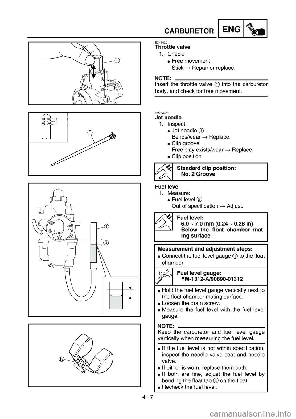
Throttle valve
1. Check:
�Free movement
Stick → Repair or replace.
NOTE:
Insert the throttle valve 1 into the carburetor
body, and check for free movement.
EC464401
Jet needle
1. Inspect:
�Jet needle 1
Bends/wear → Replace.
�Clip groove
Free play exists/wear → Replace.
�Clip position
Fuel level
1. Measure:
�Fuel level a
Out of specification → Adjust.
Standard clip position:
No. 2 Groove
Fuel level:
6.0 ~ 7.0 mm (0.24 ~ 0.28 in)
Below the float chamber mat-
ing surface
Measurement and adjustment steps:
�Connect the fuel level gauge 1 to the float
chamber.
Fuel level gauge:
YM-1312-A/90890-01312
�Hold the fuel level gauge vertically next to
the float chamber mating surface.
�Loosen the drain screw.
�Measure the fuel level with the fuel level
gauge.
NOTE:
Keep the carburetor and fuel level gauge
vertically when measuring the fuel level.
�If the fuel level is not within specification,
inspect the needle valve seat and needle
valve.
�If either is worn, replace them both.
�If both are fine, adjust the fuel level by
bending the float tab b on the float.
�Recheck the fuel level.