Page 192 of 610

3 - 10
INSP
ADJOIL PRESSURE INSPECTION/PILOT AIR SCREW
ADJUSTMENT/ENGINE IDLING SPEED ADJUSTMENT
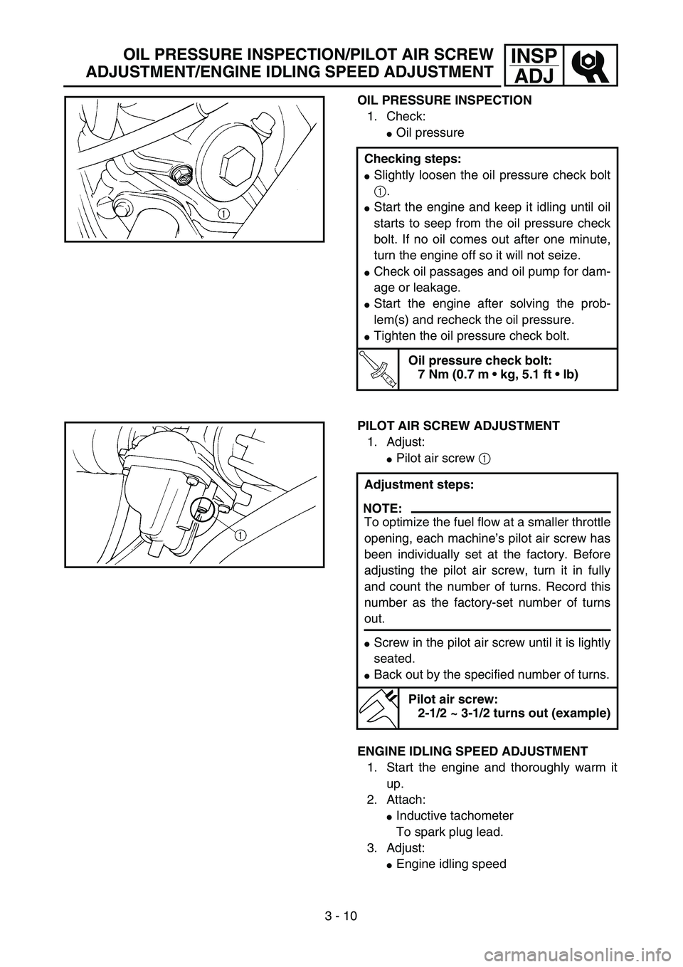
OIL PRESSURE INSPECTION
1. Check:
�Oil pressure
Checking steps:
�Slightly loosen the oil pressure check bolt
1.
�Start the engine and keep it idling until oil
starts to seep from the oil pressure check
bolt. If no oil comes out after one minute,
turn the engine off so it will not seize.
�Check oil passages and oil pump for dam-
age or leakage.
�Start the engine after solving the prob-
lem(s) and recheck the oil pressure.
�Tighten the oil pressure check bolt.
T R..
Oil pressure check bolt:
7 Nm (0.7 m • kg, 5.1 ft • lb)
PILOT AIR SCREW ADJUSTMENT
1. Adjust:
�Pilot air screw 1
Adjustment steps:
NOTE:
To optimize the fuel flow at a smaller throttle
opening, each machine’s pilot air screw has
been individually set at the factory. Before
adjusting the pilot air screw, turn it in fully
and count the number of turns. Record this
number as the factory-set number of turns
out.
�Screw in the pilot air screw until it is lightly
seated.
�Back out by the specified number of turns.
Pilot air screw:
2-1/2 ~ 3-1/2 turns out (example)
ENGINE IDLING SPEED ADJUSTMENT
1. Start the engine and thoroughly warm it
up.
2. Attach:
�Inductive tachometer
To spark plug lead.
3. Adjust:
�Engine idling speed
Page 216 of 610

3 - 22
INSP
ADJ
DRIVE CHAIN SLACK ADJUSTMENT
6. Lubricate:
�Drive chain
Drive chain lubricant:
SAE 10W-30 motor oil or suit-
able chain lubricants
DRIVE CHAIN SLACK ADJUSTMENT
1. Elevate the rear wheel by placing the
suitable stand under the engine.
2. Check:
�Drive chain slack a
In the center between the drive axle
and rear wheel axle.
Out of specification → Adjust.
NOTE:
Before checking and/or adjusting, rotate the
rear wheel through several revolutions and
check the slack several times to find the tight-
est point. Check and/or adjust chain slack with
rear wheel in this “tight chain” position.
Drive chain slack:
35 ~ 50 mm (1.4 ~ 2.0 in)
3. Adjust:
�Drive chain slack
Drive chain slack adjustment steps:
�Loosen the axle nut 1.
�Turn both drive chain pullers 2 the same
amount a and adjust them to the stopper
in the same position so that the drive chain
slack is within the specified limits.
CAUTION:
Too small chain slack will overload the
engine and other vital parts; keep the
slack within the specified limits.
�Tighten the axle nut while pushing down
the drive chain.
T R..
Axle nut:
60 Nm (6.0 m • kg, 43 ft • lb)
Page 568 of 610
–+ELEC
6 - 3
IGNITION SYSTEM
EC620000
IGNITION SYSTEM
INSPECTION STEPS
Use the following steps for checking the possibility of the malfunctioning engine being attributable to
ignition system failure and for checking the spark plug which will not spark.
*marked: Only when the ignition checker is used.
NOTE:
�Remove the following parts before inspection.
1) Seat
2) Fuel tank
�Use the following special tools in this inspection.
Dynamic spark tester:
YM-34487
Ignition checker:
90890-06754Pocket tester:
YU-3112-C/90890-03112
Spark gap test*Clean or replace
spark plug.
Check entire ignition
system for connection.Repair or replace.
Check main switch.
(TT-R125E/TT-R125LWE
only)Replace.
Check engine stop switch. Replace.
Check ignition coil. Primary coil Replace.
Secondary coil Replace.
Check CDI magneto. Pickup coil Replace.
Source coil Replace.
Replace CDI unit.
No Spark
OK
OK
OK
OK
Spark
No good
No good
No good
No good
No good
No good
OK
No good
Page 606 of 610
6 - 19
–+ELECCHARGING SYSTEM (TT-R125E/TT-R125LWE)
EC624000
COUPLERS AND LEADS CONNECTION
INSPECTION
1. Check:
�Couplers and leads connection
Rust/dust/looseness/short-circuit →
Repair or replace.
CHARGING VOLTAGE INSPECTION
1. Start the engine.
2. Inspect:
�Charging voltage
Out of specification → If no failure is
found in checking the source coil resis-
tance, replace the rectifier/regulator.
Tester (+) lead → Red lead 1
Tester (–) lead → Black lead 2
Charging
voltageTester selector
position
14.0 ~ 15.0 V at
5,000 r/minDCV-20
W
B
RY
2
1
3. Inspect:
�Charging coil resistance
Out of specification → Replace.
Tester (+) lead → White lead 1
Tester (–) lead → Black lead 2
Charging coil
resistanceTester selector
position
0.64 ~ 0.96 Ω at
20 ˚C (68 ˚F)Ω × 1
WSb
YB
1
2