Page 272 of 610

4 - 7
ENGCARBURETOR
EC464301
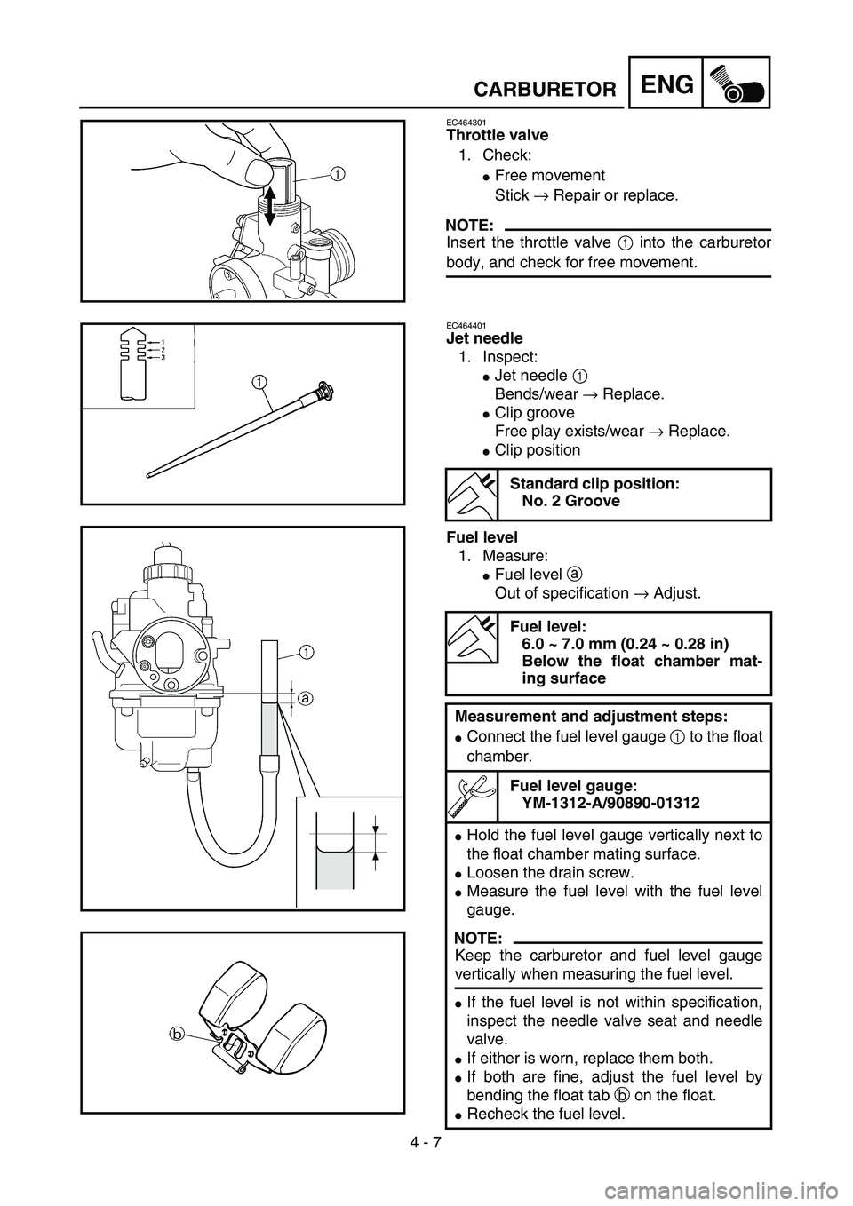
Throttle valve
1. Check:
�Free movement
Stick → Repair or replace.
NOTE:
Insert the throttle valve 1 into the carburetor
body, and check for free movement.
EC464401
Jet needle
1. Inspect:
�Jet needle 1
Bends/wear → Replace.
�Clip groove
Free play exists/wear → Replace.
�Clip position
Fuel level
1. Measure:
�Fuel level a
Out of specification → Adjust.
Standard clip position:
No. 2 Groove
Fuel level:
6.0 ~ 7.0 mm (0.24 ~ 0.28 in)
Below the float chamber mat-
ing surface
Measurement and adjustment steps:
�Connect the fuel level gauge 1 to the float
chamber.
Fuel level gauge:
YM-1312-A/90890-01312
�Hold the fuel level gauge vertically next to
the float chamber mating surface.
�Loosen the drain screw.
�Measure the fuel level with the fuel level
gauge.
NOTE:
Keep the carburetor and fuel level gauge
vertically when measuring the fuel level.
�If the fuel level is not within specification,
inspect the needle valve seat and needle
valve.
�If either is worn, replace them both.
�If both are fine, adjust the fuel level by
bending the float tab b on the float.
�Recheck the fuel level.
Page 280 of 610
4 - 11
ENGCARBURETOR
3. Install:
�Carburetor top cover 1
�Starter plunger 2
�Air vent hose 3
�Over flow hose 4
�Fuel hose 5
NOTE:
Align the slit a of the throttle valve with the tab
b of the carburetor body.
CAUTION:
In order to release the starter cable from
the twist, install the starter knob after tight-
ening the nut for the starter plunger.
4. Adjust:
�Idle speed
Refer to “ENGINE IDLING SPEED
ADJUSTMENT” section in the CHAP-
TER 3.
Page 282 of 610
4 - 12
ENGCYLINDER HEAD
CYLINDER HEAD
CYLINDER HEAD SIDE COVER AND TAPPET COVER
Extent of removal:1 Cylinder head side cover and tappet cover removal
Extent of removal Order Part name Q’ty Remarks
CYLINDER HEAD SIDE COVER
AND TAPPET COVER
REMOVAL
Preparation for removal Seat and fuel tank Refer to “SEAT, FUEL TANK AND SIDE
COVERS” section.
Muffler Refer to “MUFFLER” section.
Carburetor Refer to “CARBURETOR” section.
CDI unit Remove from the frame.
1 Engine bracket 1
2 Spark plug 1
3 Cylinder head side cover 1
4 Tappet cover 2
5 Crankshaft end accessing screw 1
6Timing mark accessing screw
1
1
Page 374 of 610
4 - 58
ENG
EC4L0000
CDI MAGNETO (TT-R125/TT-R125LW)
Extent of removal:1 CDI magneto removal
Extent of removal Order Part name Q’ty Remarks
CDI MAGNETO REMOVAL
Preparation for removal Seat and fuel tank Refer to “SAET, FUEL TANK AND SIDE
COVERS” section.
Drain the engine oil Refer to “ENGINE OIL REPLACEMENT”
section in the CHAPTER 3.
Drive sprocket cover Refer to “ENGINE REMOVAL” section.
1 CDI magneto lead 1
2 Left crankcase cover 1
3 Nut (rotor) 1
Use special tool.
Refer to “REMOVAL POINTS”.
4 Rotor 1
5 Woodruff key 1
6 Pickup coil 1
7 Lead guide 1
8Stator
1
1
CDI MAGNETO (TT-R125/TT-R125LW)
Page 380 of 610
4 - 61
ENG
CDI MAGNETO AND STARTER CLUTCH
(TT-R125E/TT-R125LWE)
CDI MAGNETO AND STARTER CLUTCH (TT-R125E/TT-R125LWE)
Extent of removal:1 Pickup coil/stator removal2 Starter clutch/wheel gear removal
Extent of removal Order Part name Q’ty Remarks
CDI MAGNETO AND STATOR
REMOVAL
Preparation for removal Fuel tank
1 CDI magneto lead 1
2 Neutral switch lead 1
3 Left crankcase cover 1
4 Nut (rotor) 1
Use special tool.
Refer to “REMOVAL POINTS”.
5 Rotor 1
6 Starter clutch 1
7 Woodruff key 1
8 Starter wheel gear 1
9 Plain washer 1
10 Plate (starter idle gear) 1
11 Starter idle gear 1
12 Lead guide 1
13Pickup coil/stator assembly
1
1
2
1
1
Page 390 of 610
4 - 66
ENGENGINE REMOVAL
ENGINE REMOVAL
Extent of removal:1 Engine removal
Extent of removal Order Part name Q’ty Remarks
ENGINE REMOVAL
Preparation for removal Hold the machine by placing the
suitable stand under the frame.
Seat, fuel tank and side covers Refer to “SEAT, FUEL TANK AND SIDE
COVERS” section.
Carburetor Refer to “CARBURETOR” section.
Muffler Refer to “MUFFLER” section.
Clutch cable Disconnect at engine side.
Spark plug cap
Disconnect the CDI magneto
lead.
Disconnect the neutral switch lead
for the TT-R125E/TT-R125LWE.
Starter motor for the TT-R125E/
TT-R125LWERefer to “ELECTRIC STARTING SYS-
TEM” section in the CHAPTER 6 for the
TT-R125E/TT-R125LWE.
Drain the engine oil. Refer to “ENGINE OIL REPLACEMENT”
section in the CHAPTER 3.
Page 554 of 610
5 - 65
CHASREAR SHOCK ABSORBER ASSEMBLY
EC580000
REAR SHOCK ABSORBER ASSEMBLY
Extent of removal:1 Rear shock absorber assembly removal
Extent of removal Order Part name Q’ty Remarks
Preparation for removalREAR SHOCK ABSORBER
ASSEMBLY REMOVAL
Hold the machine by placing the
suitable stand under the engine.
WARNINGSupport the machine securely so there is nodanger of it falling over.
Seat and side covers Refer to “SEAT, FUEL TANK AND SIDE
COVERS” section in the CHAPTER 4.
1 Bolt (rear shock absorber assem-
bly-relay arm)1 Hold the swingarm.
2 Bolt (rear shock absorber assem-
bly-frame)1
3 Bushing 1 Refer to “REMOVAL POINTS”.
4 Rear shock absorber assembly 1
1
Page 568 of 610
–+ELEC
6 - 3
IGNITION SYSTEM
EC620000
IGNITION SYSTEM
INSPECTION STEPS
Use the following steps for checking the possibility of the malfunctioning engine being attributable to
ignition system failure and for checking the spark plug which will not spark.
*marked: Only when the ignition checker is used.
NOTE:
�Remove the following parts before inspection.
1) Seat
2) Fuel tank
�Use the following special tools in this inspection.
Dynamic spark tester:
YM-34487
Ignition checker:
90890-06754Pocket tester:
YU-3112-C/90890-03112
Spark gap test*Clean or replace
spark plug.
Check entire ignition
system for connection.Repair or replace.
Check main switch.
(TT-R125E/TT-R125LWE
only)Replace.
Check engine stop switch. Replace.
Check ignition coil. Primary coil Replace.
Secondary coil Replace.
Check CDI magneto. Pickup coil Replace.
Source coil Replace.
Replace CDI unit.
No Spark
OK
OK
OK
OK
Spark
No good
No good
No good
No good
No good
No good
OK
No good