Page 70 of 351
60
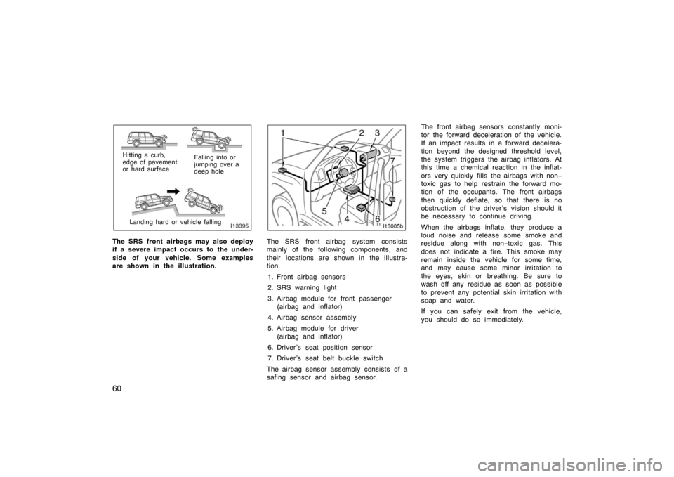
Hitting a curb,
edge of pavement
or hard surfaceFalling into or
jumping over a
deep hole
Landing hard or vehicle falling
The SRS front airbags may also deploy
if a severe impact occurs to the under-
side of your vehicle. Some examples
are shown in the illustration.The SRS front airbag system consists
mainly of the following components, and
their locations are shown in the illustra-
tion. 1. Front airbag sensors
2. SRS warning light
3. Airbag module for front passenger (airbag and inflator)
4. Airbag sensor assembly
5. Airbag module for driver (airbag and inflator)
6. Driver ’s seat position sensor
7. Driver ’s seat belt buckle switch
The airbag sensor assembly consists of a
safing sensor and airbag sensor. The front airbag sensors constantly moni-
tor the forward deceleration of the vehicle.
If an impact results in a forward decelera-
tion beyond the designed threshold level,
the system triggers the airbag inflators. At
this time a chemical reaction in the inflat-
ors very quickly fills the airbags with non
−
toxic gas to help restrain the forward mo-
tion of the occupants. The front airbags
then quickly deflate, so that there is no
obstruction of the driver ’s vision should it
be necessary to continue driving.
When the airbags inflate, they produce a
loud noise and release some smoke and
residue along with non −toxic gas. This
does not indicate a fire. This smoke may
remain inside the vehicle for some time,
and may cause some minor irritation to
the eyes, skin or breathing. Be sure to
wash off any residue as soon as possible
to prevent any potential skin irritation with
soap and water.
If you can safely exit from the vehicle,
you should do so immediately.
Page 74 of 351
64
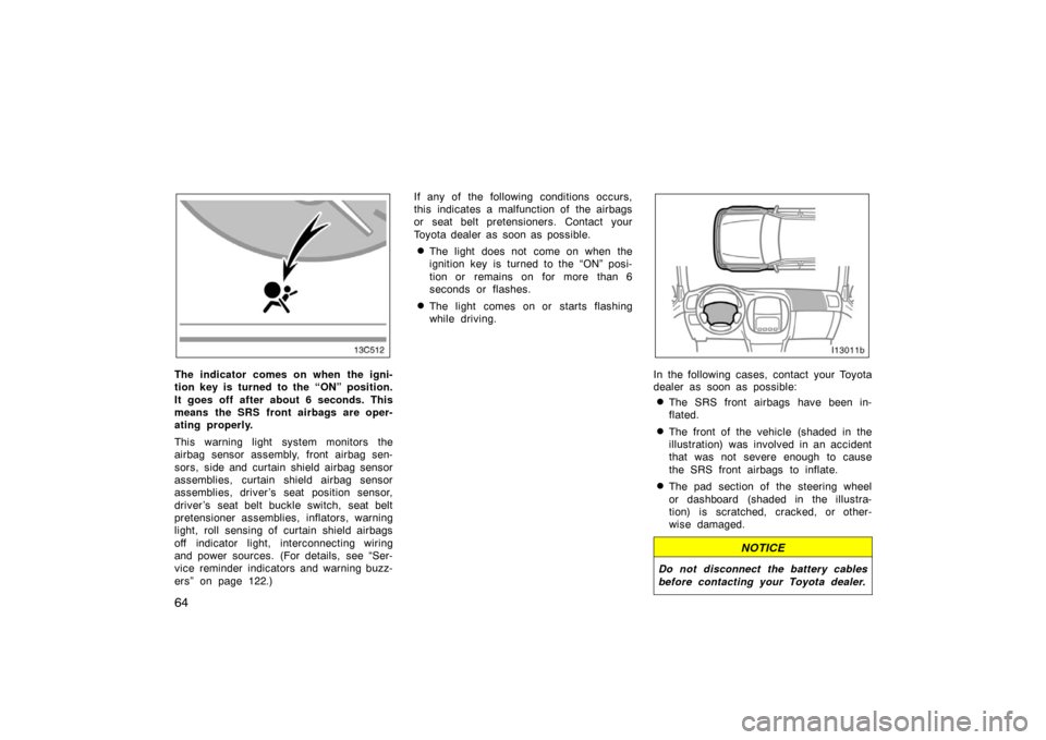
The indicator comes on when the igni-
tion key is turned to the “ON” position.
It goes off after about 6 seconds. This
means the SRS front airbags are oper-
ating properly.
This warning light system monitors the
airbag sensor assembly, front airbag sen-
sors, side and curtain shield airbag sensor
assemblies, curtain shield airbag sensor
assemblies, driver ’s seat position sensor,
driver ’s seat belt buckle switch, seat belt
pretensioner assemblies, inflators, warning
light, roll sensing of curtain shield airbags
off indicator light, interconnecting wiring
and power sources. (For details, see “Ser-
vice reminder indicators and warning buzz-
ers” on page 122.)If any of the following conditions occurs,
this indicates a malfunction of the airbags
or seat belt pretensioners. Contact your
Toyota dealer as soon as possible.
�The light does not come on when the
ignition key is turned to the “ON” posi-
tion or remains on for more than 6
seconds or flashes.
�The light comes on or starts flashing
while driving.
In the following cases, contact your Toyota
dealer as soon as possible:
�The SRS front airbags have been in-
flated.
�The front of the vehicle (shaded in the
illustration) was involved in an accident
that was not severe enough to cause
the SRS front airbags to inflate.
�The pad section of the steering wheel
or dashboard (shaded in the illustra-
tion) is scratched, cracked, or other-
wise damaged.
NOTICE
Do not disconnect the battery cables
before contacting your Toyota dealer.
Page 79 of 351
69
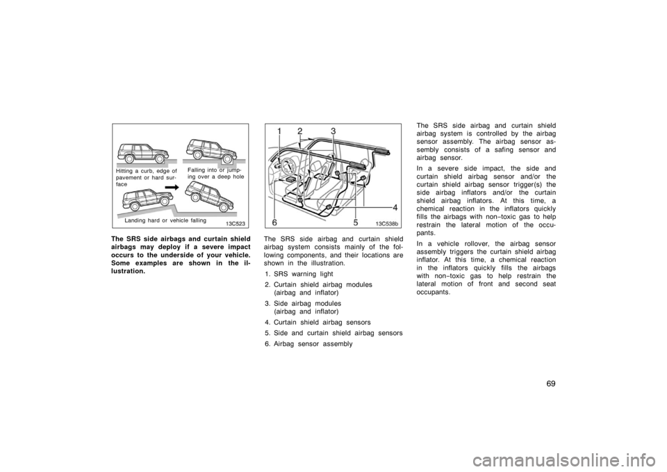
Hitting a curb, edge of
pavement or hard sur-
faceFalling into or jump-
ing over a deep hole
Landing hard or vehicle falling
The SRS side airbags and curtain shield
airbags may deploy if a severe impact
occurs to the underside of your vehicle.
Some examples are shown in the il-
lustration.
13c538b
The SRS side airbag and curtain shield
airbag system consists mainly of the fol-
lowing components, and their locations are
shown in the illustration.
1. SRS warning light
2. Curtain shield airbag modules (airbag and inflator)
3. Side airbag modules (airbag and inflator)
4. Curtain shield airbag sensors
5. Side and curtain shield airbag sensors
6. Airbag sensor assembly The SRS side airbag and curtain shield
airbag system is controlled by the airbag
sensor assembly. The airbag sensor as-
sembly consists of a safing sensor and
airbag sensor.
In a severe side impact, the side and
curtain shield airbag sensor and/or the
curtain shield airbag sensor trigger(s) the
side airbag inflators and/or the curtain
shield airbag inflators. At this time, a
chemical reaction in the inflators quickly
fills the airbags with non
−toxic gas to help
restrain the lateral motion of the occu-
pants.
In a vehicle rollover, the airbag sensor
assembly triggers the curtain shield airbag
inflator. At this time, a chemical reaction
in the inflators quickly fills the airbags
with non −toxic gas to help restrain the
lateral motion of front and second seat
occupants.
Page 84 of 351
74
�Do not place luggage heavier than
specified on the roof luggage carri-
er. Such luggage may cause the
curtain shield airbags to inflate ac-
cidentally, resulting in death or seri-
ous injury. For details, see “Roof
luggage carrier” on page 202.
Failure to follow these instructions
can result in death or serious injury.
Consult your Toyota dealer about any
repair and modification.NOTICE
Do not perform any of the following
changes without consulting your
Toyota dealer. Such changes can in-
terfere with proper operation of the
SRS side airbag and curtain shield
airbag system in some cases.
� Installation of electronic devices
such as a mobile two�way radio,
cassette tape player or compact
disc player.
� Modification of the side structure of
the passenger compartment.
� Repairs made on or near the con-
sole or front seat.
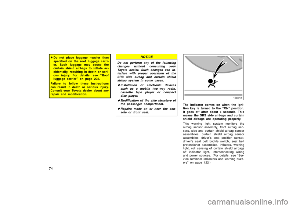
The indicator comes on when the igni-
tion key is turned to the “ON” position.
It goes off after about 6 seconds. This
means the SRS side airbags and curtain
shield airbags are operating properly.
This warning light system monitors the
airbag sensor assembly, front airbag sen-
sors, side and curtain shield airbag sensor
assemblies, curtain shield airbag sensor
assemblies, driver ’s seat position sensor,
driver’s seat belt buckle switch, seat belt
pretensioner assemblies, inflators, warning
light, roll sensing of curtain shield airbags
off indicator light, interconnecting wiring
and power sources. (For details, see “Ser-
vice reminder indicators and warning buzz-
ers” on page 122.)
Page 127 of 351
11 7
OPERATION OF INSTRUMENTS AND
CONTROLS
Gauges, Meters and Service reminder indicators
Fuel gauge11 8
. . . . . . . . . . . . . . . . . . . . . . . . . . . . . . . . . . . . .\
. . . . . . . . . . .
Engine coolant temperature gauge 11 8
. . . . . . . . . . . . . . . . . . . . . . . . . . .
Engine oil pressure gauge 11 9
. . . . . . . . . . . . . . . . . . . . . . . . . . . . . . . . . . .
Vo ltme te r 120
. . . . . . . . . . . . . . . . . . . . . . . . . . . . . . . . . . . . \
. . . . . . . . . . . . . .
Tachometer 120
. . . . . . . . . . . . . . . . . . . . . . . . . . . . . . . . . . . . \
. . . . . . . . . . . .
Odometer and two trip meters 121
. . . . . . . . . . . . . . . . . . . . . . . . . . . . . . . .
Service reminder indicators and warning buzzers 122
. . . . . . . . . . . . . .
Trip information display 129
. . . . . . . . . . . . . . . . . . . . . . . . . . . . . . . . . . . . \
. .
SECTION 1� 6
Page 128 of 351
11 8
Fuel gauge
15C004
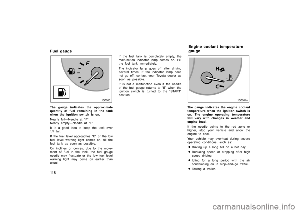
The gauge indicates the approximate
quantity of fuel remaining in the tank
when the ignition switch is on.
Nearly full—Needle at “F”
Nearly empty—Needle at “E”
It is a good idea to keep the tank over
1/4 full.
If the fuel level approaches “E” or the low
fuel level warning light comes on, fill the
fuel tank as soon as possible.
On inclines or curves, due to the move-
ment of fuel in the tank, the fuel gauge
needle may fluctuate or the low fuel level
warning light may come on earlier than
usual.If the fuel tank is completely empty, the
malfunction indicator lamp comes on. Fill
the fuel tank immediately.
The indicator lamp goes off after driving
several times. If the indicator lamp does
not go off, contact your Toyota dealer as
soon as possible.
It is not a malfunction even if the needle
of the fuel gauge returns to “E” when the
ignition switch is turned to the “START”
position.The gauge indicates the engine coolant
temperature when the ignition switch is
on. The engine operating temperature
will vary with changes in weather and
engine load.
If the needle points to the red zone or
higher, stop your vehicle and allow the
engine to cool.
Your vehicle may overheat during severe
operating conditions, such as:
�Driving up a long hill on a hot day.
�Reducing speed or stopping after high
speed driving.
�Idling for a long period with the air
conditioning on in stop
−and− go traffic.
�Towing a trailer.
Engine coolant temperature
gauge
Page 132 of 351
122
Service reminder indicators and warning buzzers
If the indicator or buzzer comes on...Do this.
(a)(indicators and buzzer)If parking brake is off, stop immediately and contact Toyota dealer.
(b)
(indicators and buzzer)
Fasten driver ’s seat belt.
(c)Fasten front passenger ’s seat belt.
(d)Stop and check.
(e)Replace engine oil.
(f)Take vehicle to Toyota dealer.
(g)Fill up tank.
Page 133 of 351
123
If the indicator or buzzer comes on...Do this.
(h)Take vehicle to Toyota dealer immediately.
(i)Take vehicle to Toyota dealer. If brake system warning light is also on, stop immedi-
ately and contact Toyota dealer.
(j)Close all side doors and back door.
(k)Shift four−wheel drive control out of “N”.
(l)Stop and check.
(m)Take vehicle to Toyota dealer.
(n)Key reminder buzzerRemove key.