Page 2552 of 5135
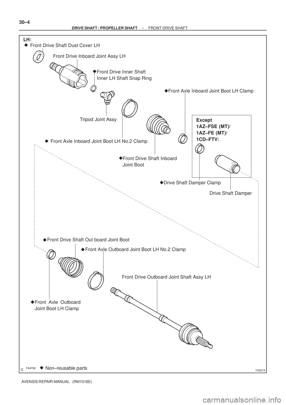
������F45574Non±reusable parts �� Front Drive Shaft Dust Cover LH
Front Drive Inboard Joint Assy LH
Front Drive Inner Shaft
Inner LH Shaft Snap Ring
Front Axle Inboard Joint Boot LH Clamp
Drive Shaft Damper Drive Shaft Damper Clamp Front Drive Shaft Inboard
Joint Boot Front Axle Inboard Joint Boot LH No.2 ClampTripod Joint Assy �
�
��
�
Front Drive Shaft Out board Joint Boot
Front Axle Outboard Joint Boot LH No.2 Clamp
�
Front Drive Outboard Joint Shaft Assy LH
Front Axle Outboard
Joint Boot LH Clamp
LH:
Except
1AZ±FSE (MT)/
1AZ±FE (MT)/
1CD±FTV:
�
� 30±4
± DRIVE SHAFT / PROPELLER SHAFTFRONT DRIVE SHAFT
AVENSIS REPAIR MANUAL (RM1018E)
Page 2553 of 5135
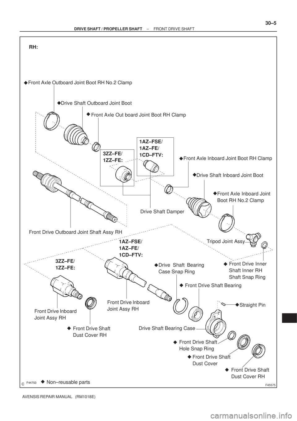
������F45575Non±reusable parts � Front Axle Outboard Joint Boot RH No.2 Clamp
Drive Shaft Outboard Joint Boot
Front Axle Out board Joint Boot RH Clamp
Drive Shaft DamperFront Axle Inboard Joint Boot RH Clamp
Drive Shaft Inboard Joint Boot
Front Axle Inboard Joint
Boot RH No.2 Clamp
�
�
Front Drive Outboard Joint Shaft Assy RH
RH:
3ZZ±FE/
1ZZ±FE:1AZ±FSE/
1AZ±FE/
1CD±FTV:
Front Drive Inboard
Joint Assy RH
Front Drive Shaft
Dust Cover RHTripod Joint Assy
Front Drive Inner
Shaft Inner RH
Shaft Snap Ring Drive Shaft Bearing
Case Snap Ring
Front Drive Shaft Bearing
Straight Pin
Drive Shaft Bearing Case
Front Drive Shaft
Hole Snap Ring
Front Drive Shaft
Dust Cover
Front Drive Shaft
Dust Cover RH �
�
� �
��
�
�
3ZZ±FE/
1ZZ±FE:
1AZ±FSE/
1AZ±FE/
1CD±FTV:
Front Drive Inboard
Joint Assy RH
�
�
�
�
± DRIVE SHAFT / PROPELLER SHAFTFRONT DRIVE SHAFT
30±5
AVENSIS REPAIR MANUAL (RM1018E)
Page 2977 of 5135
 or moreBattery
SST(s)
H42633Weight
X Y
Y
H40013
Inner Diam.
Tires
(3 or More)Width 60±24
± SUPPLEMENTAL RESTRAINT SYSTEMHORN BUTTON ASSY
AVENSIS REPAIR MANUAL (RM1018E)
(2) Move")
H4263210 m (33 ft) or moreBattery
SST(s)
H42633Weight
X Y
Y
H40013
Inner Diam.
Tires
(3 or More)Width 60±24
± SUPPLEMENTAL RESTRAINT SYSTEMHORN BUTTON ASSY
AVENSIS REPAIR MANUAL (RM1018E)
(2) Move the SST(s) to at least 10 m (33 ft) away from
the horn button assy tied down to the disc wheel.
(e) Cover the horn button assy with a cardboard box or tires.
�Covering method using a cardboard box:
Cover the horn button assy with the cardboard box
and weigh the cardboard box down in 4 places with
at least 190 N (20 kg, 44 lb).
Size of cardboard box:
Must exceed the following dimensions:
X = 460 mm (18.11 in.)
Y = 650 mm (25.59 in.)
NOTICE:
�When the dimension Y of the cardboard box exceeds
the diameter of the disc wheel with tire to which the
horn button assy is tied, X should be the following
size.
X = 460 mm (18.11 in.) + width of tire
�If a cardboard box smaller than the specified size is
used, the cardboard box will be broken by the shock
from the airbag deployment.
�Covering method using tires:
Place at least 3 tires with no disc wheels on top of
the tire with disc wheel to which the horn button assy
is tied.
Tire size: Must exceed the following dimensions
Width: 185 mm (7.28 in.)
Inner diameter: 360 mm (14.17 in.)
CAUTION:
Do not use tires with disc wheels.
NOTICE:
�The tires may be marked by the airbag deployment,
so use a redundant tires.
�Do not place the SST(s) connector under the tire be-
cause the SST(s) connector could be damaged.
Page 3057 of 5135

AVENSIS REPAIR MANUAL (RM1018E)
REPLACEMENT
HINT:
�The installation is in the reve")
610EC±01
B66569
Protrusion Part
Front
Front
Mark
Protrusion Part
61±24
±
SEAT BELT REAR SEAT BELT (WAGON MODELS)
AVENSIS REPAIR MANUAL (RM1018E)
REPLACEMENT
HINT:
�The installation is in the reverse order of the removal. However, when there is a special point concern-
ing the installation, it is indicated.
�Use the same procedures on the LH side as on the RH side.
1.REMOVE REAR DOOR SCUFF PLATE RH (See page 76±54)
2. REMOVE REAR DOOR OPENING TRIM WEATHERSTRIP RH
3.REMOVE REAR SEAT ASSY (See page 72±21)
4. REMOVE TONNEAU COVER ASSY
5. REMOVE BACK DOOR WEATHERSTRIP
6.REMOVE DECK BOARD SUB±ASSY (See page 76±54)
7.REMOVE DECK FLOOR BOX REAR (See page 76±54)
8.REMOVE DECK FLOOR BOX FRONT (See page 76±54)
9.REMOVE DECK FLOOR BOX RH (See page 76±54)
10.REMOVE REAR FLOOR FINISH PLATE (See page 76±54)
11.REMOVE DECK TRIM SIDE BOARD RH (See page 76±54)
12. REMOVE REAR SEAT 3 POINT TYPE BELT ASSY OUTER
(a) Remove the bolt and belt on the floor anchor side.
(b) Remove the 2 bolts and belt on the retractor side.
13. REMOVE REAR SEAT BELT ASSY OUTER CENTER
(a)Remove the rear seatback board RH (See page 72±21).
(b)Remove the rear seat shoulder belt cover (See page 72±21).
(c) Remove the bolt on the retractor side and remove the belt outer center c\
ompletely.
(d) Remove the bolt and belt outer center on the floor anchor side.
14. REMOVE REAR SEAT 3 POINT TYPE BELT ASSY INNER
(a) Remove the bolt and belt.
15. REMOVE REAR SEAT 3 POINT TYPE BELT ASSY INNER
(a) Remove the bolt and belt.
16. REMOVE CHILD RESTRAINT SEAT ANCHOR BRACKET SUB±ASSY RH
(a) Remove the 2 bolts and anchor bracket.
17. INSTALL CHILD RESTRAINT SEAT ANCHOR BRACKET SUB±ASSY RH
(a) Install the child restraint seat anchor bracket with the 2 bolts. Torque: 31 N �m (316 kgf �cm, 23 ft �lbf)
18. INSTALL REAR SEAT 3 POINT TYPE BELT ASSY INNER
(a) Install the belt with the bolt as shown in the illustration.
Torque: 42 N �m (430 kgf �cm, 31 ft �lbf)
NOTICE:
�Makesure that the anchor part does not run onto the
protrusion part of the floor panel.
�Do not disassemble the retractor.
19. INSTALL REAR SEAT BELT ASSY OUTER CENTER
(a) Install the belt with the bolt on the retractor side. Torque: 42 N �m (430 kgf �cm, 31 ft �lbf)
Page 3060 of 5135
610EB±01
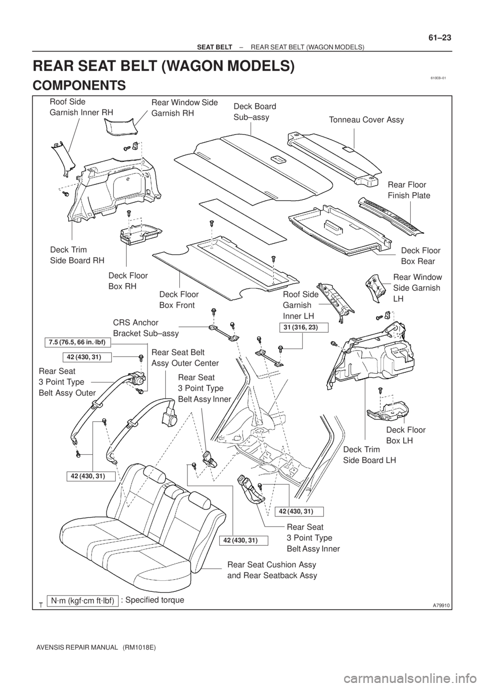
A79910N�m (kgf�cm ft�lbf): Specified torqueRear Window Side
Garnish RH
Roof Side
Garnish Inner RH
Deck Trim
Side Board RH
Deck Floor
Box RH
Deck Floor
Box Front
Tonneau Cover Assy
Deck Board
Sub±assy
Deck Floor
Box Rear
Deck Trim
Side Board LH
Deck Floor
Box LH
Rear Window
Side Garnish
LH
Roof Side
Garnish
Inner LHRear Floor
Finish Plate
Rear Seat Cushion Assy
and Rear Seatback Assy
Rear Seat
3 Point Type
Belt Assy Inner
42 (430, 31)
Rear Seat
3 Point Type
Belt Assy Outer
Rear Seat Belt
Assy Outer Center
Rear Seat
3 Point Type
Belt Assy Inner
31 (316, 23)CRS Anchor
Bracket Sub±assy
7.5 (76.5, 66 in.�lbf)
42 (430, 31)
42 (430, 31)
42 (430, 31)
± SEAT BELTREAR SEAT BELT (WAGON MODELS)
61±23
AVENSIS REPAIR MANUAL (RM1018E)
REAR SEAT BELT (WAGON MODELS)
COMPONENTS
Page 3061 of 5135

AVENSIS REPAIR MANUAL (RM1018E)
REPLACEMENT
HINT:
�The installation is in the r")
610EA±01
B66569
Protrusion Part
Front
Front
Mark
Protrusion Part
61±20
±
SEAT BELT REAR SEAT BELT (LIFTBACK MODELS)
AVENSIS REPAIR MANUAL (RM1018E)
REPLACEMENT
HINT:
�The installation is in the reverse order of the removal. However, when there is a special point concern-
ing the installation, it is indicated.
�Use the same procedures on the LH side as on the RH side.
1.REMOVE REAR DOOR SCUFF PLATE RH (See page 76±45)
2. REMOVE REAR DOOR OPENING TRIM WEATHERSTRIP RH
3.REMOVE REAR SEAT ASSY (See page 72±21)
4.REMOVE PACKAGE TRAY TRIM PANEL ASSY (See page 76±45)
5. REMOVE BACK DOOR WEATHERSTRIP
6.REMOVE REAR FLOOR FINISH PLATE (See page 76±45)
7.REMOVE ROOF SIDE GARNISH INNER RH (See page 76±45)
8.REMOVE DECK TRIM SIDE PANEL ASSY RH (See page 76±45)
9. REMOVE REAR SEAT 3 POINT TYPE BELT ASSY OUTER
(a) Remove the bolt and belt on the floor anchor side.
(b) Remove the 2 bolts and belt on the retractor side.
10. REMOVE REAR SEAT BELT ASSY OUTER CENTER
(a)Remove the rear seatback board RH (See page 72±21).
(b)Remove the rear seat shoulder belt cover (See page 72±21).
(c) Remove the bolt on the retractor side and remove the belt completely.
(d) Remove the bolt and belt assy outer center on the floor anchor side.
11. REMOVE REAR SEAT 3 POINT TYPE BELT ASSY INNER
(a) Remove the bolt and belt.
12. REMOVE REAR SEAT 3 POINT TYPE BELT ASSY INNER
(a) Remove the bolt and belt.
13. REMOVE CHILD RESTRAINT SEAT ANCHOR BRACKET SUB±ASSY RH
(a) Remove the 2 bolts and anchor bracket.
14. INSTALL CHILD RESTRAINT SEAT ANCHOR BRACKET SUB±ASSY RH
(a) Install the child restraint seat anchor bracket with the 2 bolts. Torque: 31 N �m (316 kgf �cm, 23 ft �lbf)
15. INSTALL REAR SEAT 3 POINT TYPE BELT ASSY INNER
(a) Install the belt with the bolt as shown in the illustration.
Torque: 42 N �m (430 kgf �cm, 31 ft �lbf)
NOTICE:
Make sure that the anchor part does not run onto the protru-
sion part of the floor panel.
16. INSTALL REAR SEAT BELT ASSY OUTER CENTER
(a) Install the belt with the bolt on the retractor side. Torque: 42 N �m (430 kgf �cm, 31 ft �lbf)
Page 3065 of 5135

61±15
AVENSIS REPAIR MANUAL (RM1018E)
REPLACEMENT
HINT:
�The installation is in the reve")
610ED±01
B66569
Protrusion Part
Front
Front
Mark
Protrusion Part
±
SEAT BELT REAR SEAT BELT (SEDAN MODELS)
61±15
AVENSIS REPAIR MANUAL (RM1018E)
REPLACEMENT
HINT:
�The installation is in the reverse order of the removal. However, when there is a special point concern-
ing the installation, it is indicated.
�Use the same procedures on the LH side as on the RH side.
1.REMOVE REAR DOOR SCUFF PLATE RH (See page 76±36)
2.REMOVE REAR DOOR SCUFF PLATE LH (See page 76±36)
3. REMOVE REAR DOOR OPENING TRIM WEATHERSTRIP RH
4. REMOVE REAR DOOR OPENING TRIM WEATHERSTRIP LH
5.REMOVE REAR SEAT ASSY (See page 72±27, 72±32)
6.REMOVE ROOF SIDE GARNISH INNER RH (See page 76±36)
7.REMOVE ROOF SIDE GARNISH INNER LH (See page 76±36)
8.REMOVE PACKAGE TRAY TRIM PANEL ASSY (See page 76±36)
9. REMOVE REAR SEAT 3 POINT TYPE BELT ASSY OUTER
(a) Remove the bolt and belt on the floor anchor side.
(b) Remove the 2 bolts and belt on the retractor side.
10. REMOVE REAR SEAT BELT ASSY OUTER CENTER
(a) United fixed type: Remove the bolt and belt on the floor anchor side.
(b) United fixed type:
Remove the bolt and belt on the retractor side.
(c) 40/60 folding type: Remove the rear seatback board RH (See page 72±27).
(d) 40/60 folding type: Remove the rear seat shoulder belt cover (See page 72±27).
(e) 40/60 folding type: Remove the bolt on the retractor side and remove the belt completely.
(f) Remove the bolt and belt outer center on the floor anchor side.
11. REMOVE REAR SEAT 3 POINT TYPE BELT ASSY INNER
(a) Remove the bolt and belt.
12. REMOVE REAR SEAT 3 POINT TYPE BELT ASSY INNER
(a) Remove the bolt and belt.
13. REMOVE CHILD RESTRAINT SEAT ANCHOR BRACKET SUB±ASSY RH
(a) Remove the 2 bolts and anchor bracket.
14. INSTALL CHILD RESTRAINT SEAT ANCHOR BRACKET SUB±ASSY RH
(a) Install the child restraint seat anchor bracket with the 2 bolts. Torque: 31 N �m (316 kgf �cm, 23 ft �lbf)
15. INSTALL REAR SEAT 3 POINT TYPE BELT ASSY INNER
(a) Install the belt assy with the bolt as shown in the illustra-
tion.
Torque: 42 N �m (430 kgf �cm, 31 ft �lbf)
NOTICE:
Make sure that the anchor part does not run onto the protru-
sion part of the floor panel.
16. INSTALL REAR SEAT BELT ASSY OUTER CENTER (UNITED FIXED TYPE REAR SEAT)
Page 3100 of 5135
650T1±01
I352352Clamps
I35236
I35238
I35239
65±26
±
LIGHTING CENTER STOP LAMP ASSY
AVENSIS REPAIR MANUAL (RM1018E)
CENTER STOP LAMP ASSY
REPLACEMENT
1.REMOVE REAR SPOILER (WAGON MODELS) (See page 76±30)
2.REMOVE BACK DOOR TRIM BOARD ASSY (LIFTBACK MODELS) (See page 75±40) 3. REMOVE CENTER STOP LAMP ASSY (SEDANMODELS)
(a) Remove the center stop lamp assy as shown in the il- lustration.
(b) Disconnect the connector.
(c) Remove the center stop lamp bulb as shown in the il- lustration.
4. REMOVE CENTER STOP LAMP ASSY (WAGON MODELS)
(a) Remove the 2 screws and center stop lamp assy.
5. REMOVE CENTER STOP LAMP ASSY (LIFTBACK MODELS)
(a) Disconnect the connector.
(b) Remove the 3 screws and center stop lamp assy.
(c) Remove the center stop lamp socket and the bulb.

CENTER STOP LAMP ASSY
REPLACEMENT
1.REMOVE REAR SPOILER (WAGON MODELS) (See page")