Page 948 of 5135
![TOYOTA AVENSIS 2005 Service Repair Manual D25148
TA C
12345 768
9 1 0111 21 3 1 514 16
± DIAGNOSTICSELECTRONIC CONTROLLED AUTOMATIC
TRANSAXLE [ECT] (U241E(1AZ±FSE))05±927
AVENSIS REPAIR MANUAL (RM1018E)
(b) Measure the time lag.
(1) When](/manual-img/14/57441/w960_57441-947.png "TOYOTA AVENSIS 2005 Service Repair Manual D25148
TA C
12345 768
9 1 0111 21 3 1 514 16
± DIAGNOSTICSELECTRONIC CONTROLLED AUTOMATIC
TRANSAXLE [ECT] (U241E(1AZ±FSE))05±927
AVENSIS REPAIR MANUAL (RM1018E)
(b) Measure the time lag.
(1) When")
D25148
TA C
12345 768
9 1 0111 21 3 1 514 16
± DIAGNOSTICSELECTRONIC CONTROLLED AUTOMATIC
TRANSAXLE [ECT] (U241E(1AZ±FSE))05±927
AVENSIS REPAIR MANUAL (RM1018E)
(b) Measure the time lag.
(1) When the shift lever is shifted while the engine is idling, there will be a certain time lapse or lag
before the shock can be felt. This is used for checking the condition of the direct clutch, forward
clutch, and 1st and reverse brake.
NOTICE:
�Do the test at normal operating ATF temperature 50 to 80�C (122 to 176�F).
�Be sure to allow 1 minute interval between tests.
�Take 3 measurements and take the average value.
(2) Chock the 4 wheels.
(3) Connect the hand±held tester to DLC3 or tachome-
ter to terminal TAC of DLC3 with SST.
SST 09843±18030
(4) Start engine and check idle speed.
Idle speed: 650 � 50 rpm (In N range and A/C OFF)
(5) Shift the lever from N to D range. Using a stop
watch, measure the time from when the lever is
shifted until the shock is felt.
Time lag: N � D less than 1.2 seconds
(6) In the same way, measure the time lag for N � R.
Time lag: N � R less than 1.5 seconds
Evaluation (If N � D or N � R time lag is longer than the specified):
ProblemPossible cause
N � D time lag is longer
� Line pressure too low
� Forward clutch worn
� U/D one±way clutch not operating properly
N � R time lag is longer
� Line pressure too low
� Direct clutch worn
� 1st and reverse brake worn
� U/D one±way clutch not operating properly
Page 1012 of 5135
![TOYOTA AVENSIS 2005 Service Repair Manual ±
DIAGNOSTICS ELECTRONIC CONTROLLED AUTOMATIC
TRANSAXLE [ECT] (U241E(1AZ±FSE))05±937
AVENSIS REPAIR MANUAL (RM1018E)
Chapter 3: Off±vehicle Repair
(� : U241E AUTOMATIC TRANSAXLE Repair Manual Pu](/manual-img/14/57441/w960_57441-1011.png "TOYOTA AVENSIS 2005 Service Repair Manual ±
DIAGNOSTICS ELECTRONIC CONTROLLED AUTOMATIC
TRANSAXLE [ECT] (U241E(1AZ±FSE))05±937
AVENSIS REPAIR MANUAL (RM1018E)
Chapter 3: Off±vehicle Repair
(� : U241E AUTOMATIC TRANSAXLE Repair Manual Pu")
±
DIAGNOSTICS ELECTRONIC CONTROLLED AUTOMATIC
TRANSAXLE [ECT] (U241E(1AZ±FSE))05±937
AVENSIS REPAIR MANUAL (RM1018E)
Chapter 3: Off±vehicle Repair
(� : U241E AUTOMATIC TRANSAXLE Repair Manual Pub. No. RM840U)
SymptomSuspect AreaSee page
Vehicle does not move in any forward range or reverse range
1. Front and rear planetary gear
2. U/D planetary gear
3. U/D one±way clutch (F
2)
4. Forward clutch (C
1)
5. U/D brake (B
3)
�
�
�
�
�
Vehicle does not move in R range
1. Front and rear planetary gear unit
2. U/D planetary gear
3. Direct clutch (C
2)
4. U/D brake (C
3)
5. 1st and reverse brake (B
2)
�
�
�
�
�
No up±shift (1st � 2nd)1. No.1 one±way clutch (F1)
2. 2nd brake (B
1)
�
�
No up±shift (2nd � 3rd)Direct clutch (C2)�
No up±shift (3rd � O/D)U/D clutch (C3)�
No lock±up or No lock±up offTorque converter clutch40±37
Harsh engagement (N � D)
1. Forward clutch (C1)
2. U/D one±way clutch (F
2)
3. No.1 one±way clutch (F
1)
�
�
�
Harsh engagement (N � R)1. Direct clutch (C2)
2. 1st and reverse brake (B
2)
�
�
Harsh engagement (Lock±up)Torque converter clutch40±37
Slip or shudder (Forward position: After warm±up)
1. Torque converter clutch
2. Forward clutch (C
1)
3. Direct clutch (C
2)
4. U/D brake (C
3)
5. No.1 one±way clutch (F
1)
6. U/D one±way clutch (F
2)
40±37 �
�
�
�
�
Slip or shudder (R range)1. Direct clutch (C2)
2. 1st and reverse brake (B
2)
�
�
Slip or shudder (1st)No.1 one±way clutch (F1)�
Slip or shudder (2nd)1. U/D one±way clutch (F2)
2. 2nd brake (B
1)
�
�
Slip or shudder (3rd)Direct clutch (C2)�
Slip or shudder (O/D)U/D clutch (C3)�
No engine braking (1st ± 3rd: D range)U/D brake (B3)�
No engine braking (1st: L range)1st and reverse brake (B2)�
No engine braking (2nd: 2 range)2nd brake (B1)�
Poor acceleration (All range)1. Torque converter clutch
2. U/D planetary gear40±37 �
Poor acceleration (O/D)1. U/D clutch (C3)
2. U/D planetary gear�
�
Large shift shock or engine stalls when starting off or stoppingTorque converter clutch40±37
Page 1047 of 5135
D26539
E1
ECT Solenoid
Y
2R±B12
E12
STECM
ST
± DIAGNOSTICSELECTRONIC CONTROLLED AUTOMATIC
TRANSAXLE [ECT] (U341E)05±1027
AVENSIS REPAIR MANUAL (RM1018E)
DTC P1790 ST SOLENOID CIRCUIT MALFUNCTION
CIRCUIT DESCRIPTION
Shift solenoid valve ST is switched ON±OFF by a signal from ECM so that let in or out timing of O/D and
2nd brake is adjusted by operating orifice control valve. Therefore, shift solenoid valve ST operates when
letting in or out reverse clutch.
If it is broken, the shift shock becomes big.
DTC No.DTC Detection ConditionTrouble Area
P1790
ECM memorizes DTC P1790 if (a) or (b) condition below is
detected once or more.
(a) Solenoid resistance is 30 � or lower (short circuit) when
solenoid is energized.
(b) Solenoid resistance is 100 k� or higher (open circuit) when
solenoid is not energized.
�Open or short in shift solenoid valve ST circuit
�Shift solenoid valve ST
�ECM
WIRING DIAGRAM
05C8M±01
Page 1076 of 5135

AVENSIS REPAIR MANUAL (RM1018E)
Chapter 3: Off±vehicle Repair
( � : U340E, U341E AUTOMATIC TRANSAXLE Repair Manual Pub.](/manual-img/14/57441/w960_57441-1075.png "TOYOTA AVENSIS 2005 Service Repair Manual 05±1002±
DIAGNOSTICS ELECTRONIC CONTROLLED AUTOMATIC
TRANSAXLE [ECT](U341E)
AVENSIS REPAIR MANUAL (RM1018E)
Chapter 3: Off±vehicle Repair
( � : U340E, U341E AUTOMATIC TRANSAXLE Repair Manual Pub.")
05±1002±
DIAGNOSTICS ELECTRONIC CONTROLLED AUTOMATIC
TRANSAXLE [ECT](U341E)
AVENSIS REPAIR MANUAL (RM1018E)
Chapter 3: Off±vehicle Repair
( � : U340E, U341E AUTOMATIC TRANSAXLE Repair Manual Pub. No. RM824E)
SymptomSuspect AreaSee page
Vehicle does not move in any forward range and reverse range
1. Planetary gear unit
2. Forward clutch
3. One±way clutch No.2
4. Reverse Clutch
5. 1st and reverse brake�
�
�
�
�
Vehicle does not move in R range
1. Planetary gear unit
2. Reverse Clutch
3. 1st and reverse brake�
�
�
No up±shift (1st � 2nd)1. 2nd brake
2. One±way clutch No.1�
�
No up±shift (2nd � 3rd)Direct clutch�
No up±shift (3rd � O/D)O/D and 2nd brake�
No lock±up or No lock±up offTorque converter clutch40±37
Harsh engagement (N � D)1. Forward clutch
2. One±way clutch No.2�
�
Harsh engagement (N � R)1. Reverse clutch
2. 1st and reverse brake�
�
Harsh engagement (Lock±up)Torque converter clutch40±37
Harsh engagement (1st � 2nd)1. 2nd brake
2. One±way clutch No.1�
�
Harsh engagement (2nd � 3rd)Direct clutch�
Harsh engagement (3rd � O/D)O/D and 2nd brake�
Slip or shudder (Forward range)
1. Torque converter clutch
2. Forward clutch
3. Direct clutch
4. O/D and 2nd brake
5. 2nd brake
6. One±way clutch No.1
7. One±way clutch No.240±37
�
�
�
�
�
�
Slip or shudder (Reverse range)1. Reverse clutch
2. 1st and reverse brake�
�
Slip or shudder (1st)One±way clutch No.2�
Slip or shudder (2nd)1. 2nd brake
2. One±way clutch No.1�
�
Slip or shudder (3rd)Direct clutch�
Slip or shudder (O/D)O/D and 2nd brake�
No engine braking (1st)1st and reverse brake�
No engine braking (2nd)O/D and 2nd brake�
Poor acceleration (All range)Torque converter clutch40±37
Large shift shock or engine stalls when starting off or stoppingTorque converter clutch40±37
Page 2005 of 5135

13±3
AVENSIS REPAIR MANUAL (RM1018E)
TURBO CHARGER SYSTEM (1CD±FTV)
PRECAUTION
1. MAINTENANCE PRECAUTION
(a) Do not stop the")
1302Y±03
A77119
A77120
A77121
± INTAKETURBO CHARGER SYSTEM (1CD±FTV)
13±3
AVENSIS REPAIR MANUAL (RM1018E)
TURBO CHARGER SYSTEM (1CD±FTV)
PRECAUTION
1. MAINTENANCE PRECAUTION
(a) Do not stop the engine immediately after pulling a trailer,
or after driving at a high speed, or uphill drive. Let the en-
gine Idle for 20 to 120 seconds before turn the ignition
switch OFF (According as the driving condition, the idling
time varies).
(b) Avoid quick acceleration or quickly accelerating the en-
gine RPM immediately after the starting a cold engine.
(c) If the turbocharger is found to be defective, it must be re-
placed. Also, inspect a source of the trouble including
conditions of the turbocharger that having been used. Re-
pair or replace the followings as necessary:
(1) Engine oil (Level and quality)
(2) Oil lines leading to the turbocharger
(d) Pay due attention when removing and reinstalling the
turbocharger assembly. Do not drop, or do not give shock,
or do not grasp easily±deformed assembly parts such as
the actuator or push rod in removal and reinstallation.
(e) Before removal, cover both the intake and exhaust ports
and the oil inlet to prevent dirt or foreign objects from be-
ing introduced.
(f) If replacing the turbocharger, check for deposits in the oil
pipe. If necessary, replace the oil pipe too.
(g) Thoroughly remove old gasket sticking to the lubrication
oil pipe flange and the turbocharger oil flange.
(h) If replacing the bolt(s) or nut(s), must use Toyota genuine
parts to prevent breakage or deformation.
(i) If replacing the turbocharger, put 20 cm
3 (1.2 cu in.) of
fresh oil into the turbocharger oil inlet hole and turn the tur-
bine wheel by hand to spread oil to the bearing.
(j) If overhauling or replacing the engine, cut the fuel supply
after reassembly and crank the engine for 30 seconds to
feed oil throughout the engine then run the engine at idle
for 60 seconds.
Page 2459 of 5135
260DP±01
F44614
Front Shock Absorber with Coil Spring
Front Stabilizer Link Assy LH
47 (479, 35)
220 (2,240, 162)
74 (755, 55)
19 (194, 14)
Speed Sensor
Front LH
Front Flexible Hose
Front Suspension Support Dust Cover LH
Front Suspension Support Sub±assy LH
Front Suspension
Support LH Dust Seal
Front Coil Spring
Seat Upper LH
Front Axle Assy
Front Coil Spring Insulator Upper LH
Front Coil Spring LH
N�m (kgf�cm, ft�lbf) : Specified torque
�Non±reusable part
Front Spring
Bumper LH
Front Coil
Spring Insulator
Lower LH
Shock Absorber
Assy Front LH
39 (398, 29)
� 26±2
± FRONT SUSPENSIONFRONT SUSPENSION
AVENSIS REPAIR MANUAL (RM1018E)
FRONT SUSPENSION
COMPONENTS
Page 2461 of 5135
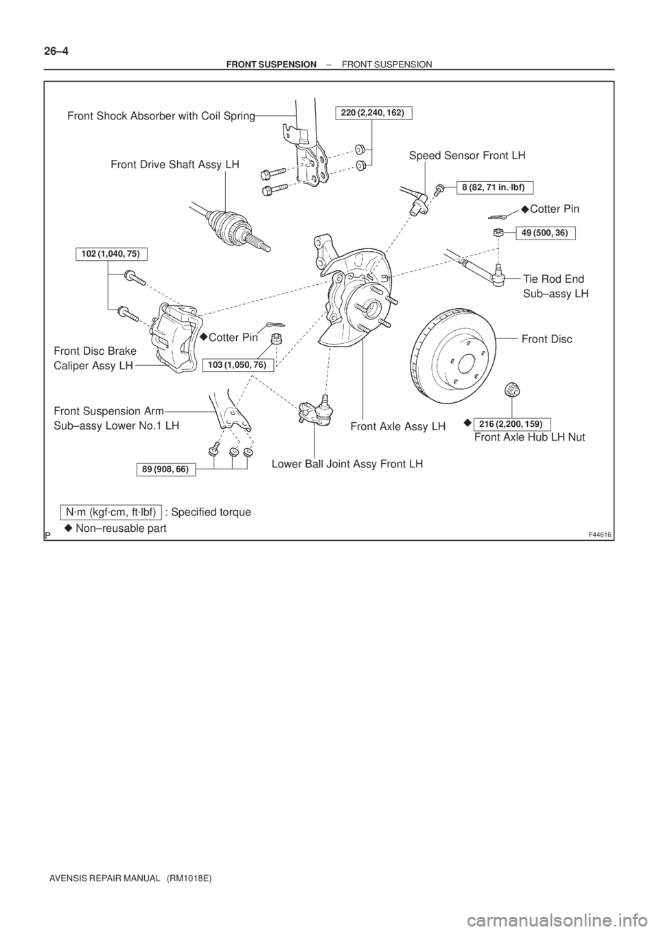
F44616
89 (908, 66)
102 (1,040, 75)
220 (2,240, 162)
8 (82, 71 in.�lbf)
49 (500, 36)
103 (1,050, 76)
216 (2,200, 159)
Front Shock Absorber with Coil Spring
Front Drive Shaft Assy LHSpeed Sensor Front LH
Cotter Pin
Front Disc
Tie Rod End
Sub±assy LH
Cotter Pin
Front Disc Brake
Caliper Assy LH
Front Suspension Arm
Sub±assy Lower No.1 LH
Lower Ball Joint Assy Front LH
Front Axle Assy LHFront Axle Hub LH Nut
N�m (kgf�cm, ft�lbf) : Specified torque
�Non±reusable part�
�� 26±4
± FRONT SUSPENSIONFRONT SUSPENSION
AVENSIS REPAIR MANUAL (RM1018E)
Page 2463 of 5135

FRONT SUSPENSION SYSTEM
PROBLEM SYMPTOMS TABLE
Use the table below to help you find the cause of the probl")
2600K±06
±
FRONT SUSPENSION FRONT SUSPENSION SYSTEM
26±1
AVENSIS REPAIR MANUAL (RM1018E)
FRONT SUSPENSION SYSTEM
PROBLEM SYMPTOMS TABLE
Use the table below to help you find the cause of the problem. The numbers \
indicate the priority of
the likely cause of the problem. Check each part in order. If necessary, replace these parts.
SymptomSuspect AreaSee page
Wander/pulls
4. Tire (Worn or improperly inflated)
5. Wheel alignment (Incorrect)
6. Steering linkage (Loose or worn)
7. Hub bearing (Worn)
8. Steering gear (Out of adjustment or broken)
9. Suspension parts (Worn)28±1
26±6
±
30±2
51±28
51±36
±
Bottoming
1. Vehicle (Overloaded)
2. Spring (Weak)
3. Shock absorber (Worn)±
26±10
26±10
Sways/pitches
1. Tire (Worn or improperly inflated)
2. Stabilizer bar (Bent or broken)
3. Shock absorber (Worn)28±1
26±26
26±10
Front wheel shimmy
1. Tire (Worn or improperly inflated)
2. Wheel (Out of balance)
3. Shock absorber (Worn)
4. Wheel alignment (Incorrect)
5. Ball joint (Worn)
6. Hub bearing (Worn)
7. Steering linkage (Loose or worn)
8. Steering gear (Out of adjustment or broken)28±1
28±1
26±10 26±6
26±24
30±2 ±
51±28
51±36
Abnormal tire wear
1. Tire (Worn or improperly inflated)
2. Wheel alignment (Incorrect)
3. Shock absorber (Worn)
4. Suspension parts (Worn)28±1
26±6
26±10 ±
![TOYOTA AVENSIS 2005 Service Repair Manual D26539
E1
ECT Solenoid
Y
2R±B12
E12
STECM
ST
± DIAGNOSTICSELECTRONIC CONTROLLED AUTOMATIC
TRANSAXLE [ECT] (U341E)05±1027
AVENSIS REPAIR MANUAL (RM1018E)
DTC P1790 ST SOLENOID CIRCUIT MALFUNCTION](/manual-img/14/57441/w960_57441-1046.png "TOYOTA AVENSIS 2005 Service Repair Manual D26539
E1
ECT Solenoid
Y
2R±B12
E12
STECM
ST
± DIAGNOSTICSELECTRONIC CONTROLLED AUTOMATIC
TRANSAXLE [ECT] (U341E)05±1027
AVENSIS REPAIR MANUAL (RM1018E)
DTC P1790 ST SOLENOID CIRCUIT MALFUNCTION")

220 (2,240, 162)
74 (755, 55)
19 (194, 14)
Speed Sensor
Front LH
Front Flexible Hose
Front Suspension")