Page 4718 of 5135
1308N−01
A84393
(a)
(b)
(a)
(a)
(b)
A93661
(a)
(a) (a)
(a) (b)
(a)
(b)
13
−12
−
INTAKE TURBOCHARGER SUB −ASSY (1CD −FTV)(From
September, 2003)
AVENSIS Supplement (RM1045E)
REPLACEMENT
1. REMOVE ENGINE UNDER COVER SUB −ASSY NO.1
2. DRAIN ENGINE COOLANT (See page 16 −19)
3. REMOVE RADIATOR SUPPORT OPENING COVER
4. REMOVE ENGINE COVER SUB −ASSY NO.1
(a) Remove the 5 nuts and engine cover.
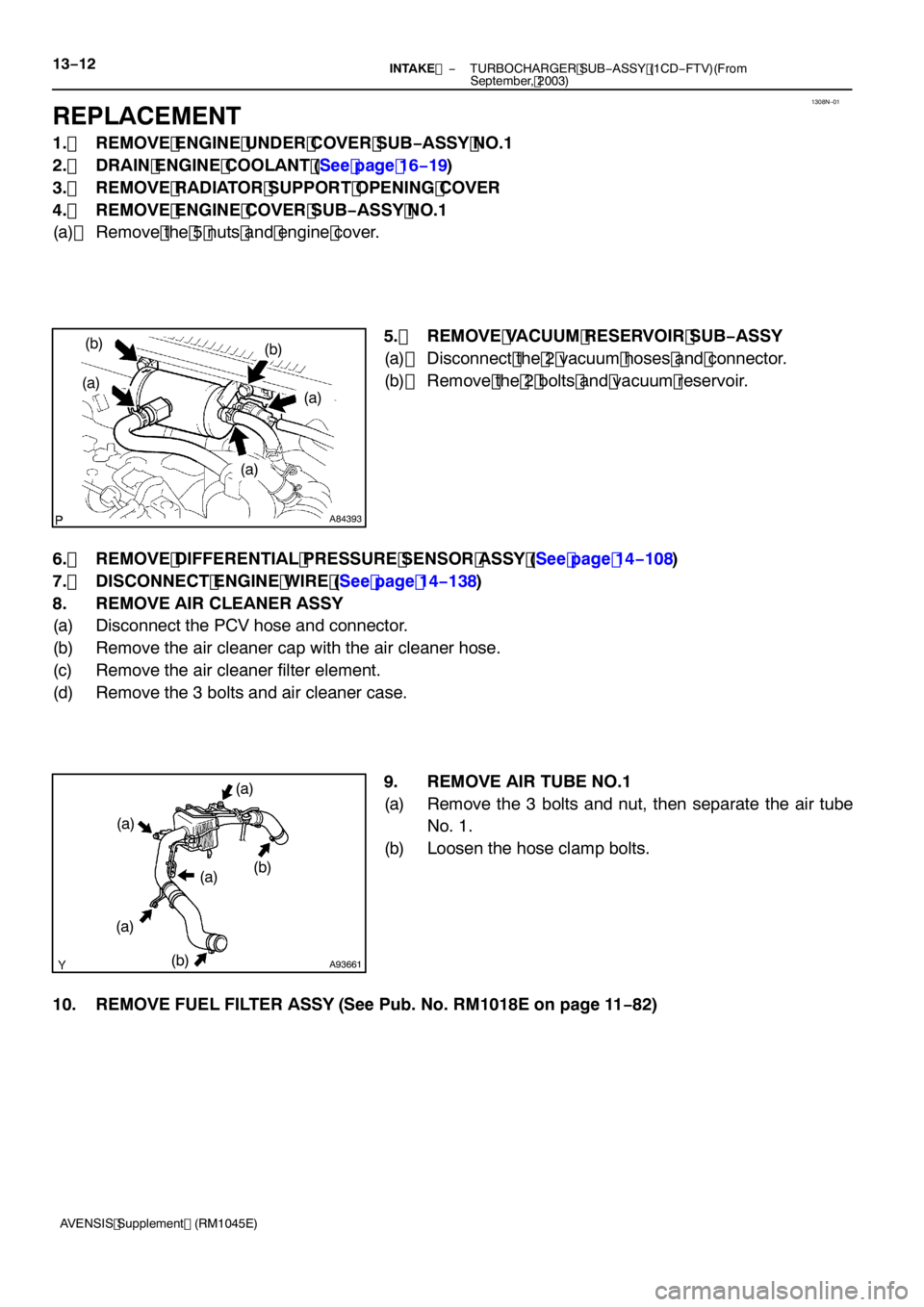
5. REMOVE VACUUM RESERVOIR SUB −ASSY
(a) Disconnect the 2 vacuum hoses and connector.
(b) Remove the 2 bolts and vacuum reservoir.
6. REMOVE DIFFERENTIAL PRESSURE SENSOR ASSY (See page 14 −108)
7. DISCONNECT ENGINE WIRE (See page 14 −138)
8. REMOVE AIR CLEANER ASSY
(a) Disconnect the PCV hose and connector.
(b) Remove the air cleaner cap with the air cleaner hose.
(c) Remove the air cleaner filter element.
(d) Remove the 3 bolts and air cleaner case.
9. REMOVE AIR TUBE NO.1
(a) Remove the 3 bolts and nut, then separate the air tubeNo. 1.
(b) Loosen the hose clamp bolts.
10. REMOVE FUEL FILTER ASSY (See Pub. No. RM1018E on page 11 −82)
Page 4724 of 5135

A85753
13−18−
INTAKE TURBOCHARGER SUB −ASSY (1CD −FTV)(From
September, 2003)
AVENSIS Supplement (RM1045E)
38. INSTALL MANIFOLD STAY NO.2
(a) Install the manifold stay No. 2, then temporarily tighten the bolt.
(b) Temporarily tighten the nut while pushing the manifold
stay No. 2 toward the cylinder head.
Torque: 8.0 N �m (82 kgf �cm, 71 in. �lbf)
HINT:
No clearance between the stay and cylinder head should be
confirmed.
(c) Tighten the bolt.
Torque: 56 N �m (571 kgf �cm, 41 ft �lbf)
(d) Tighten the nut. Torque: 56 N �m (571 kgf �cm, 41 ft �lbf)
39. INSTALL VACUUM TRANSMITTING PIPE SUB −ASSY NO.2 (See page 14 −108)
SST 09023 −38200
40. INSTALL VACUUM TRANSMITTING PIPE SUB −ASSY NO.1 (See page 14 −108)
SST 09023 −38200
41. INSTALL EXHAUST GAS TEMPERATURE SENSOR (See page 14 −108)
SST 09023 −38400
42. INSTALL EGR PIPE INSULATOR Torque: 12 N �m (122 kgf �cm, 8.9 ft �lbf)
43. INSTALL GENERATOR ASSY (See Pub. No. RM1018E on page 19 −29)
44. INSTALL EXHAUST MANIFOLD HEAT INSULATOR NO.2 Torque: 12 N �m (122 kgf �cm, 8.9 ft �lbf)
45. INSTALL TURBO INSULATOR NO.1 Torque: 20 N �m (204 kgf �cm, 15 ft �lbf)
46. INSTALL TURBO INSULATOR NO.2 Torque: 20 N �m (204 kgf �cm, 15 ft �lbf)
47. INSTALL EXHAUST PIPE ASSY (W/ COLD AREA) Torque: 7.5 N �m (76 kgf �cm, 66 in. �lbf)
48. INSTALL EXHAUST PIPE ASSY FRONT (See page 15 −6)
49. INSTALL FLOOR PANEL BRACE FRONT (See page 15 −6)
50. INSTALL HEATER BRACKET (W/ COLD AREA)
Torque: 7.5 N �m (76 kgf �cm, 66 in. �lbf)
51. INSTALL HEATER PUMP ASSY (W/ COLD AREA)
Torque: 7.5 N �m (76 kgf �cm, 66 in. �lbf)
52. INSTALL FUEL FILTER ASSY (See Pub. No. RM1018E on page 11 −82)
Page 4988 of 5135
05–130
– DIAGNOSTICSSFI SYSTEM (1ZZ–FE/3ZZ–FE)(From February, 2004)
AVENSIS REPAIR MANUAL SUPPLEMENT
(RM1098E)
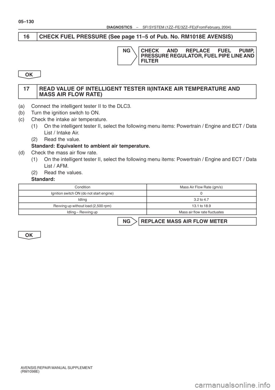
16 CHECK FUEL PRESSURE (See page 11–5 of Pub. No. RM1018E AVENSIS)
NG CHECK AND REPLACE FUEL PUMP,
PRESSURE REGULATOR, FUEL PIPE LINE AND
FILTER
OK
17 READ VALUE OF INTELLIGENT TESTER II(INTAKE AIR TEMPERATURE AND
MASS AIR FLOW RATE)
(a) Connect the intelligent tester II to the DLC3.
(b) Turn the ignition switch to ON.
(c) Check the intake air temperature.
(1) On the intelligent tester II, select the following menu items: Powertrain / Engine and ECT / Data
List / Intake Air.
(2) Read the value.
Standard: Equivalent to ambient air temperature.
(d) Check the mass air flow rate.
(1) On the intelligent tester II, select the following menu items: Powertrain / Engine and ECT / Data
List / AFM.
(2) Read the values.
Standard:
ConditionMass Air Flow Rate (gm/s)
Ignition switch ON (do not start engine)0
Idling3.2 to 4.7
Revving up without load (2,500 rpm)13.1 to 18.9
Idling – Revving upMass air flow rate fluctuates
NG REPLACE MASS AIR FLOW METER
OK