2005 SUZUKI SWIFT camshaft torque
[x] Cancel search: camshaft torquePage 23 of 1496
Downloaded from www.Manualslib.com manuals search engine General Information: 0A-2
SAS: Steering Angle Sensor
SDM: Sensing and Diagnostic Module (Air Bag Controller, Air bag Control Module)
SDT: Smart Diagnostic Tester
SFI: Sequential Multipor t Fuel Injection
SOHC: Single Over Head Camshaft
T:
TBI: Throttle Body Fuel Injection (Single-Point Fuel
Injection, SPI)
TCC: Torque Converter Clutch
TCM: Transmission Control Module (A/T Controller, A/T
Control Module)
TDC: Top Dead Center
TP Sensor: Throttle Position Sensor TVV:
Thermal Vacuum Valve (Thermal Vacuum
Switching Valve, TVSV, Bi metal Vacuum Switching
Valve, BVSV)
TWC: Three Way Catalytic Converter (Three Way
Catalyst)
2WD: 2 Wheel Drive
U:
USB: Universal Serial Bus
V:
VIN: Vehicle Identification Number
VSS: Vehicle Speed Sensor
VVT: Variable Valve Timing (Camshaft Position Control)
W:
WU-OC: Warm Up Oxidation Catalytic Converter
WU-TWC: Warm Up Three Way Catalytic Converter
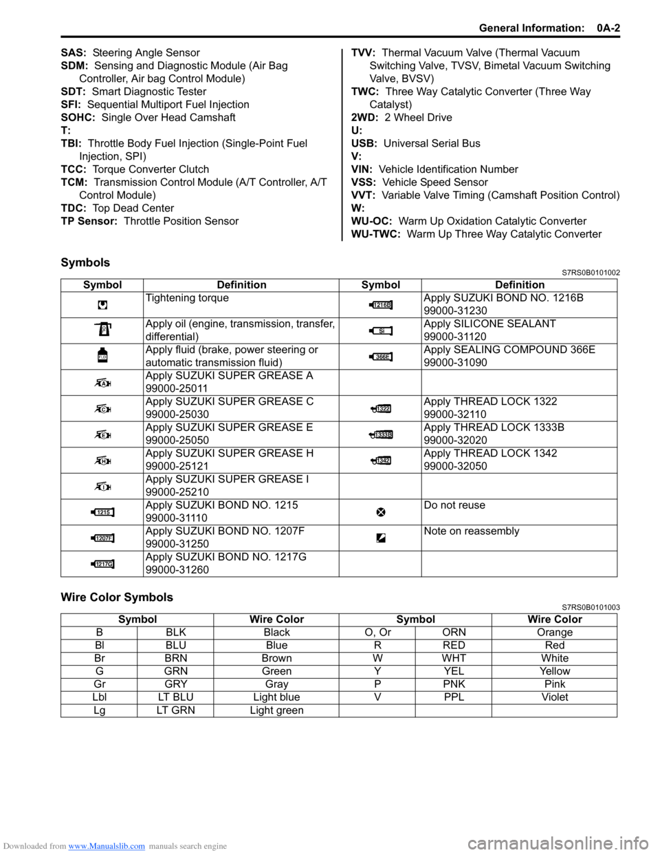
SymbolsS7RS0B0101002
Wire Color SymbolsS7RS0B0101003
Symbol Definition SymbolDefinition
Tightening torque Apply SUZUKI BOND NO. 1216B
99000-31230
Apply oil (engine, transmission, transfer,
differential) Apply SILICONE SEALANT
99000-31120
Apply fluid (brake, power steering or
automatic transmission fluid) Apply SEALING COMPOUND 366E
99000-31090
Apply SUZUKI SUPER GREASE A
99000-25011
Apply SUZUKI SUPER GREASE C
99000-25030 Apply THREAD LOCK 1322
99000-32110
Apply SUZUKI SUPER GREASE E
99000-25050 Apply THREAD LOCK 1333B
99000-32020
Apply SUZUKI SUPER GREASE H
99000-25121 Apply THREAD LOCK 1342
99000-32050
Apply SUZUKI SUPER GREASE I
99000-25210
Apply SUZUKI BOND NO. 1215
99000-31110 Do not reuse
Apply SUZUKI BO ND NO. 1207F
99000-31250 Note on reassembly
Apply SUZUKI BO ND NO. 1217G
99000-31260
Symbol Wire Color SymbolWire Color
B BLK Black O, Or ORN Orange
Bl BLU Blue RRED Red
Br BRN Brown WWHT White
G GRN Green YYEL Yellow
Gr GRY Gray PPNK Pink
Lbl LT BLU Light blueVPPL Violet
Lg LT GRN Light green
Page 34 of 1496
Downloaded from www.Manualslib.com manuals search engine 0B-4 Maintenance and Lubrication:
Accessory Drive Belt ReplacementS7RS0B0206002
Water Pump and Generator Drive Belt
Replace belt with new one referring to “Water Pump /
Generator Drive Belt Removal and Installation in Section
1J”.
A/C Compressor Drive Belt
Replace belt with new one referring to “Compressor
Drive Belt Removal and Inst allation in Section 7B”.
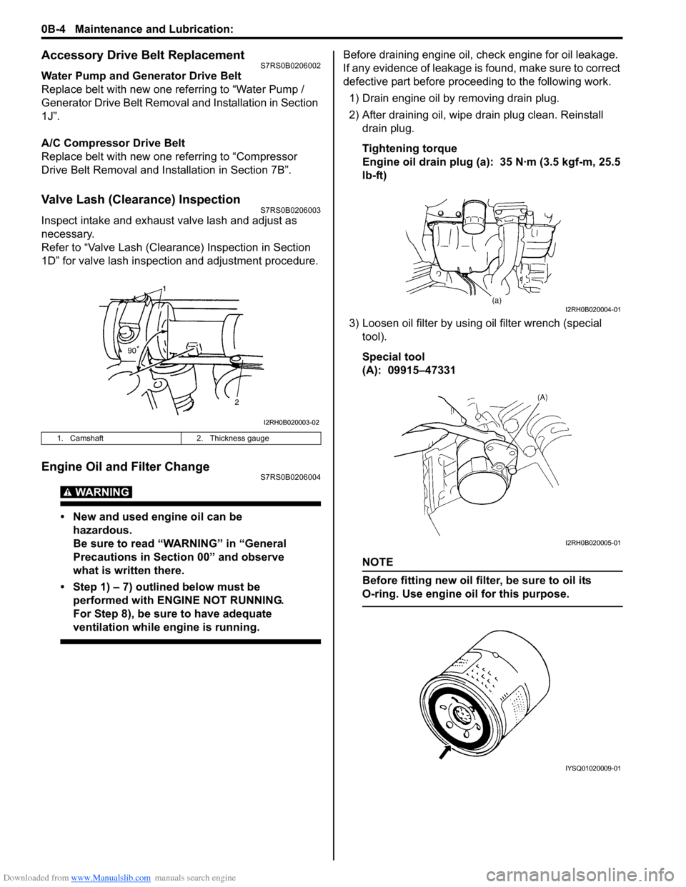
Valve Lash (Clearance) InspectionS7RS0B0206003
Inspect intake and exhaust valve lash and adjust as
necessary.
Refer to “Valve Lash (Clearance) Inspection in Section
1D” for valve lash inspection and adjustment procedure.
Engine Oil and Filter ChangeS7RS0B0206004
WARNING!
• New and used engine oil can be
hazardous.
Be sure to read “WARNING” in “General
Precautions in Section 00” and observe
what is written there.
• Step 1) – 7) outlined below must be performed with ENGINE NOT RUNNING.
For Step 8), be sure to have adequate
ventilation while engine is running.
Before draining engine oil, check engine for oil leakage.
If any evidence of leakage is found, make sure to correct
defective part before proceeding to the following work.
1) Drain engine oil by removing drain plug.
2) After draining oil, wipe drain plug clean. Reinstall drain plug.
Tightening torque
Engine oil drain plug (a): 35 N·m (3.5 kgf-m, 25.5
lb-ft)
3) Loosen oil filter by using oil filter wrench (special
tool).
Special tool
(A): 09915–47331
NOTE
Before fitting new oil filter, be sure to oil its
O-ring. Use engine oil for this purpose.
1. Camshaft 2. Thickness gauge
I2RH0B020003-02
I2RH0B020004-01
I2RH0B020005-01
IYSQ01020009-01
Page 47 of 1496

Downloaded from www.Manualslib.com manuals search engine Table of Contents 1-iii
EVAP Canister Purge Valve and Its Circuit
Inspection.......................................................... 1B-2
Vacuum Passage Inspection .............................. 1B-3
Vacuum Hose and Purge Valve Chamber Inspection.......................................................... 1B-3
EVAP Canister Purge Valve Inspection .............. 1B-3
EVAP Canister Inspection ... ................................ 1B-4
EGR Valve Removal and Installation .................. 1B-4
EGR Valve Inspection ......................................... 1B-4
PCV Hose Inspection .......................................... 1B-4
PCV Valve Inspection ......................................... 1B-5
Special Tools and Equipmen t ............................. 1B-5
Special Tool ........................................................ 1B-5
Engine Electrical Devices .. ..................... 1C-1
Repair Instructions .............................................. 1C-1
ECM Removal and Installation ............................ 1C-1
MAP Sensor Inspection ...................................... 1C-2
Electric Throttle Body Assembly On-Vehicle
Inspection.......................................................... 1C-2
Electric Throttle Body System Calibration ........... 1C-5
APP Sensor Assembly On-V ehicle Inspection .... 1C-5
APP Sensor Assembly Removal and Installation ......................................................... 1C-5
APP Sensor Assembly Inspection ...................... 1C-6
ECT Sensor Removal and In stallation ................ 1C-6
ECT Sensor Inspection ....................................... 1C-7
HO2S-1 and HO2S-2 Heater On-Vehicle Inspection.......................................................... 1C-7
HO2S-1 and HO2S-2 Removal and Installation ......................................................... 1C-7
CMP Sensor Removal and In stallation ............... 1C-8
Camshaft Position (CMP) Se nsor Inspection ...... 1C-8
CKP Sensor Removal and Installation ................ 1C-9
CKP Sensor Inspection ....................................... 1C-9
Knock Sensor Removal and Installation ........... 1C-10
Main Relay, Fuel Pump Relay and Starting
Motor Control Relay Inspection....................... 1C-10
MAF and IAT Sensor On-Vehicle Inspection .... 1C-11
MAF and IAT Sensor Removal and Installation ....................................................... 1C-11
MAF and IAT Sensor Inspection ....................... 1C-12
Electric Load Current Sensor On-Vehicle Inspection........................................................ 1C-12
Specifications ..................................................... 1C-13
Tightening Torque Specifications ...................... 1C-13
Engine Mechanical ......... ......................... 1D-1
General Description ............................................. 1D-1
Engine Construction Description ......................... 1D-1
Camshaft Position Control (VVT Variable Valve Timing) System Description .................... 1D-2
Diagnostic Information and Procedures ............ 1D-4 Compression Check ............................................ 1D-4
Engine Vacuum Check ....................................... 1D-5
Valve Lash (Clearance) Inspection ..................... 1D-6
Repair Instructions .............................................. 1D-9 Air Cleaner Components ..................................... 1D-9
Air Cleaner Element Removal and Installation .... 1D-9 Air Cleaner Element Ins
pection and Cleaning ..1D-10
Cylinder Head Co ver Removal and
Installation .......................................................1D-10
Throttle Body and Intake Manifold
Components ....................................................1D-12
Throttle Body On-Vehicle Inspection.................1D-13
Electric Throttle Body Assembly Removal and Installation .......................................................1D-13
Throttle Body Cleaning......................................1D-14
Intake Manifold Removal and Installation .........1D-14
Engine Mountings Components ........................1D-16
Engine Assembly Removal and Installation ......1D-17
Timing Chain Cover Components .....................1D-20
Timing Chain Cover Removal and Installation ..1D-21
Timing Chain Cover Inspection .........................1D-23
Oil Control Valve Removal and Installation .......1D-23
Oil Control Valve Inspection ..............................1D-24
Timing Chain and Chain Tensioner Components ....................................................1D-24
Timing Chain and Chain Tensioner Removal and Installation ................................................1D-25
Timing Chain and Chain Tensioner Inspection ..1D-27
Camshaft, Tappet and Shim Components ........1D-28
Camshaft, Tappet and Shim Removal and Installation .......................................................1D-29
Camshaft, Tappet and Shim Inspection ............1D-31
Valves and Cylinder Head Components ...........1D-34
Valves and Cylinder Head Removal and
Installation .......................................................1D-35
Valves and Cylinder Head Disassembly and Assembly.........................................................1D-37
Valves and Valve Guides Inspection.................1D-40
Cylinder Head Inspection . .................................1D-42
Valve Spring Inspection ....................................1D-43
Pistons, Piston Rings , Connecting Rods and
Cylinders Components ....................................1D-44
Pistons, Piston Rings , Connecting Rods and
Cylinders Removal and Installation .................1D-45
Pistons, Piston Rings , Connecting Rods and
Cylinders Disassembly and Assembly ............1D-46
Cylinders, Pistons and Piston Rings Inspection ........................................................1D-47
Piston Pins and Connecting Rods Inspection ...1D-49
Crank Pin and Connecting Rod Bearings Inspection ........................................................1D-50
Main Bearings, Cran kshaft and Cylinder
Block Components ..........................................1D-53
Main Bearings, Cran kshaft and Cylinder
Block Removal and Installa tion .......................1D-54
Crankshaft Inspection .......................................1D-57
Main Bearings Inspection . .................................1D-59
Sensor Plate Inspection ....................................1D-63
Rear Oil Seal Inspection ...................................1D-63
Flywheel Inspection...........................................1D-63
Cylinder Block Inspection ..................................1D-63
Specifications .................... .................................1D-64
Tightening Torque Specifications ......................1D-64
Special Tools and Equipmen t ...........................1D-66
Recommended Service Material .......................1D-66
Special Tool ......................................................1D-66
Page 280 of 1496
Downloaded from www.Manualslib.com manuals search engine 1C-8 Engine Electrical Devices:
Installation
Reverse removal procedure noting the following.
• Tighten heated oxygen sensor to specified torque.Tightening torque
Heated oxygen sensor (a): 45 N·m (4.5 kgf-m,
32.5 lb-ft)
• Install exhaust manifold referring to “Exhaust Manifold Removal and Installation in Section 1K”, if removed.
• Connect connector of heated oxygen sensor and clamp wire harness securely.
• After installing heated oxygen sensor, start engine and check that no exhaust gas leakage exists.
CMP Sensor Removal and InstallationS7RS0B1306012
Removal
1) Disconnect negative (–) cable at battery.
2) Disconnect connector from CMP sensor.
3) Remove CMP sensor from cylinder head.
Installation 1) Install CMP sensor to cylinder head.
Tightening torque
CMP sensor bolt (a): 10 N·m (1.0 kgf-m, 7.5 lb-ft)
2) Connect connector to CMP sensor securely.
3) Connect negative (–) cable to battery.
Camshaft Position (CMP) Sensor InspectionS7RS0B1306013
Visual check
• Check that O-ring is free from damage.
• Check that end face of sensor and signal rotor tooth are free from any metal particles and damage.
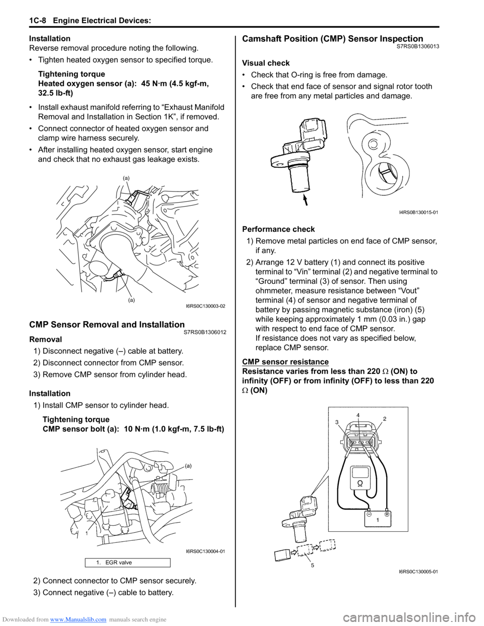
Performance check 1) Remove metal particles on end face of CMP sensor, if any.
2) Arrange 12 V battery (1) and connect its positive terminal to “Vin” terminal (2) and negative terminal to
“Ground” terminal (3) of sensor. Then using
ohmmeter, measure resistance between “Vout”
terminal (4) of sensor and negative terminal of
battery by passing magnetic substance (iron) (5)
while keeping approximately 1 mm (0.03 in.) gap
with respect to end face of CMP sensor.
If resistance does not vary as specified below,
replace CMP sensor.
CMP sensor resistance
Resistance varies from less than 220 Ω (ON) to
infinity (OFF) or from infinity (OFF) to less than 220
Ω (ON)
1. EGR valve
(a)
(a)
I6RS0C130003-02
I6RS0C130004-01
I4RS0B130015-01
I6RS0C130005-01
Page 293 of 1496
Downloaded from www.Manualslib.com manuals search engine Engine Mechanical: 1D-8
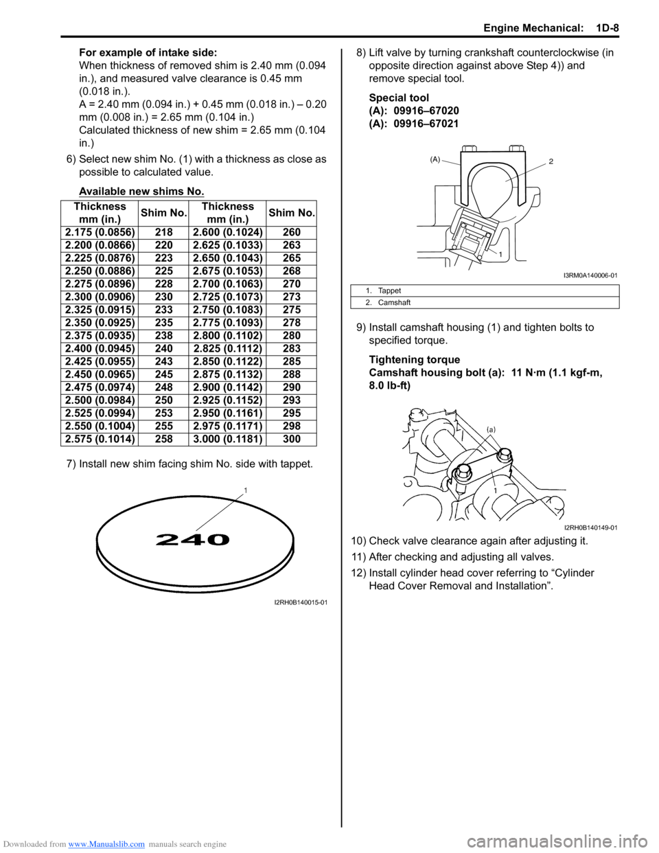
For example of intake side:
When thickness of removed shim is 2.40 mm (0.094
in.), and measured valve clearance is 0.45 mm
(0.018 in.).
A = 2.40 mm (0.094 in.) + 0.45 mm (0.018 in.) – 0.20
mm (0.008 in.) = 2.65 mm (0.104 in.)
Calculated thickness of new shim = 2.65 mm (0.104
in.)
6) Select new shim No. (1) with a thickness as close as possible to calculated value.
Available new shims No.
7) Install new shim facing shim No. side with tappet. 8) Lift valve by turning crankshaft counterclockwise (in
opposite direction against above Step 4)) and
remove special tool.
Special tool
(A): 09916–67020
(A): 09916–67021
9) Install camshaft housing (1) and tighten bolts to specified torque.
Tightening torque
Camshaft housing bolt (a ): 11 N·m (1.1 kgf-m,
8.0 lb-ft)
10) Check valve clearance again after adjusting it. 11) After checking and adjusting all valves.
12) Install cylinder head cover referring to “Cylinder Head Cover Removal and Installation”.
Thickness
mm (in.) Shim No.Thickness
mm (in.) Shim No.
2.175 (0.0856) 218 2.600 (0.1024) 260
2.200 (0.0866) 220 2.625 (0.1033) 263
2.225 (0.0876) 223 2.650 (0.1043) 265
2.250 (0.0886) 225 2.675 (0.1053) 268
2.275 (0.0896) 228 2.700 (0.1063) 270
2.300 (0.0906) 230 2.725 (0.1073) 273
2.325 (0.0915) 233 2.750 (0.1083) 275
2.350 (0.0925) 235 2.775 (0.1093) 278
2.375 (0.0935) 238 2.800 (0.1102) 280
2.400 (0.0945) 240 2.825 (0.1112) 283
2.425 (0.0955) 243 2.850 (0.1122) 285
2.450 (0.0965) 245 2.875 (0.1132) 288
2.475 (0.0974) 248 2.900 (0.1142) 290
2.500 (0.0984) 250 2.925 (0.1152) 293
2.525 (0.0994) 253 2.950 (0.1161) 295
2.550 (0.1004) 255 2.975 (0.1171) 298
2.575 (0.1014) 258 3.000 (0.1181) 300
I2RH0B140015-01
1. Tappet
2. Camshaft
(A)2
1
I3RM0A140006-01
I2RH0B140149-01
Page 311 of 1496

Downloaded from www.Manualslib.com manuals search engine Engine Mechanical: 1D-26
3) Install timing chain by aligning dark blue plate (1) of timing chain and triangle mark (2) on camshaft
timing sprocket as shown in figure.
4) Fit crankshaft timing sprocket to timing chain by aligning gold plate (3) of timing chain and circle mark
(4) on crankshaft timing sprocket. Then install
crankshaft timing sprocket fitted with chain to
crankshaft.
5) Apply engine oil to sliding surface of timing chain No.1 guide (1) and install it as shown in figure.
Tighten guide bolts to specified torque.
Tightening torque
Timing chain No.1 guide bolt (a): 9 N·m (0.9 kgf-
m, 6.5 lb-ft) 6) Apply engine oil to sliding surface of chain tensioner
(1) and install chain tensioner and spacer.
Tighten tensioner bolt to specified torque.
Tightening torque
Timing chain tensioner bolt (a): 25 N·m (2.5 kgf-
m, 18.0 lb-ft)
7) Check that match marks (2) on intake and exhaust camshaft timing sprockets are in match with dark
blue plates (1) of timing chain and match mark (4) on
crankshaft timing sprocket is in match with gold plate
(3) of timing chain.
[A]: View C
34
1
1
2
2
Approx. Approx.
C[A]
I6RS0C140016-02
I2RH0B140062-01
[A]: View C
I2RH0B140063-01
34
1
1
2
2
Approx. Approx.
C[A]
I6RS0C140016-02
Page 312 of 1496

Downloaded from www.Manualslib.com manuals search engine 1D-27 Engine Mechanical:
8) Screw in plunger (1) by turning body (2) in arrow direction and install a reta iner (3) (wire) to hold
plunger in place.
9) Install timing chain tensioner adjuster assembly (1) with a retainer (2).
Tighten adjuster bolts to specified torque and then
remove a retainer from chain tensioner adjuster
assembly.
Tightening torque
Timing chain tensioner adjuster bolt (a): 11 N·m
(1.1 kgf-m, 8.0 lb-ft)
10) Apply engine oil to timing chain, and then turn crankshaft clockwise by 2 revolutions and check that
match marks (1) are at the following specific
positions.
• Intake and exhaust camshaft timing sprockets makes (1) are in match with notches (2) on
cylinder head.
• Crankshaft sprocket key (3) is in match with notch of cylinder block (4).
• Crankshaft sprocket key (3) is on upside of crankshaft as shown in figure. 11) Install timing chain cover referring to “Timing Chain
Cover Removal and Installation”.
Timing Chain and Chain Tensioner InspectionS7RS0B1406019
Timing Chain No.1 Guide
Check shoe (1) for wear or damage.
Timing Chain Tensioner
Check shoe (1) for wear or damage.
I2RH0B140065-01
I2RH0B140066-01
1
1
2
3 4
I6RS0C140017-01
I2RH0B140068-01
I2RH0B140069-01
Page 316 of 1496
Downloaded from www.Manualslib.com manuals search engine 1D-31 Engine Mechanical:
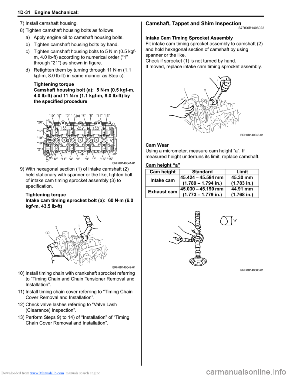
7) Install camshaft housing.
8) Tighten camshaft housing bolts as follows.a) Apply engine oil to camshaft housing bolts.
b) Tighten camshaft housing bolts by hand.
c) Tighten camshaft housing bolts to 5 N ⋅m (0.5 kgf-
m, 4.0 lb-ft) according to numerical order (“1”
through “21”) as shown in figure.
d) Retighten them by turning through 11 N⋅ m (1.1
kgf-m, 8.0 lb-ft) in same manner as Step c).
Tightening torque
Camshaft housing bolt (a): 5 N ⋅m (0.5 kgf-m,
4.0 lb-ft) and 11 N ⋅m (1.1 kgf-m, 8.0 lb-ft) by
the specified procedure
9) With hexagonal section (1) of intake camshaft (2) held stationary with spanner or the like, tighten bolt
of intake cam timing sp rocket assembly (3) to
specification.
Tightening torque
Intake cam timing sprocket bolt (a): 60 N·m (6.0
kgf-m, 43.5 lb-ft)
10) Install timing chain with cr ankshaft sprocket referring
to “Timing Chain and Chain Tensioner Removal and
Installation”.
11) Install timing chain cover referring to “Timing Chain Cover Removal and Installation”.
12) Check valve lashes referring to “Valve Lash (Clearance) Inspection”.
13) Perform Steps 9) to 14) of “Installation” of “Timing Chain Cover Removal and Installation”.Camshaft, Tappet and Shim InspectionS7RS0B1406022
Intake Cam Timing Sprocket Assembly
Fit intake cam timing sprocket assembly to camshaft (2)
and hold hexagonal section of camshaft by using
spanner or the like.
Check if sprocket (1) is not turned by hand.
If moved, replace intake ca m timing sprocket assembly.
Cam Wear
Using a micrometer, measure cam height “a”. If
measured height underruns its limit, replace camshaft.
Cam height “a”
“10”“9” “2” “1”,(a) “6” “5” “14” “13”
“20”
“17” “19”
“18”
“21”
“12”“11”
“4” “3” “8” “7” “16” “15”
I3RH0B140041-01
1
2
3
(a)
I3RH0B140042-01
Cam height Standard Limit
Intake cam 45.424 – 45.584 mm
(1.789 – 1.794 in.) 45.30 mm
(1.783 in.)
Exhaust cam 45.030 – 45.190 mm
(1.773 – 1.779 in.) 44.91 mm
(1.768 in.)
2
1
I3RH0B140043-01
I2RH0B140080-01