2005 SUZUKI SWIFT air filter removal
[x] Cancel search: air filter removalPage 36 of 1496
Downloaded from www.Manualslib.com manuals search engine 0B-6 Maintenance and Lubrication:
Exhaust System InspectionS7RS0B0206006
WARNING!
To avoid danger of being burned, do not
touch exhaust system when it is still hot.
Any service on exhaust system should be
performed when it is cool.
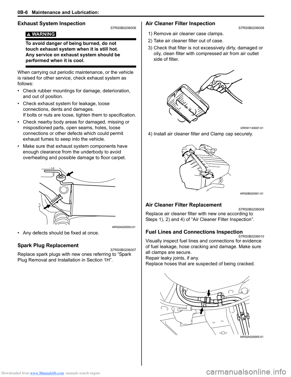
When carrying out periodic maintenance, or the vehicle
is raised for other service, check exhaust system as
follows:
• Check rubber mountings for damage, deterioration, and out of position.
• Check exhaust system for leakage, loose connections, dents and damages.
If bolts or nuts are loose, tighten them to specification.
• Check nearby body areas for damaged, missing or mispositioned parts, ope n seams, holes, loose
connections or other defects which could permit
exhaust fumes to seep into the vehicle.
• Make sure that exhaust system components have enough clearance from the underbody to avoid
overheating and possible damage to floor carpet.
• Any defects should be fixed at once.
Spark Plug ReplacementS7RS0B0206007
Replace spark plugs with new ones referring to “Spark
Plug Removal and Installation in Section 1H”.
Air Cleaner Filter InspectionS7RS0B0206008
1) Remove air cleaner case clamps.
2) Take air cleaner filter out of case.
3) Check that filter is not excessively dirty, damaged or oily, clean filter with compressed air from air outlet
side of filter.
4) Install air cleaner filter and Clamp cap securely.
Air Cleaner Filter ReplacementS7RS0B0206009
Replace air cleaner filter with new one according to
Steps 1), 2) and 4) of “Air Cleaner Filter Inspection”.
Fuel Lines and Connections InspectionS7RS0B0206010
Visually inspect fuel lines and connections for evidence
of fuel leakage, hose cracking and damage. Make sure
all clamps are secure.
Repair leaky joints, if any.
Replace hoses that are suspected of being cracked.
I4RS0A020003-01
I2RH01140007-01
I4RS0B020001-01
I4RS0A020005-01
Page 37 of 1496
Downloaded from www.Manualslib.com manuals search engine Maintenance and Lubrication: 0B-7
Fuel Filter ReplacementS7RS0B0206011
Fuel filter is installed in fuel pump assembly in fuel tank.
Replace fuel filter or fuel pump assembly with new one,
referring to “Fuel Pump Assembly Removal and
Installation in Section 1G” for proper procedure.
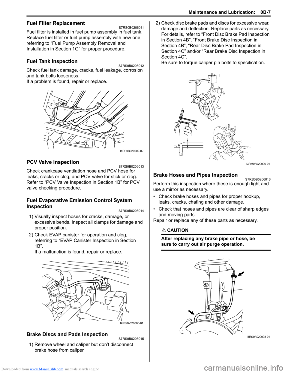
Fuel Tank InspectionS7RS0B0206012
Check fuel tank damage, cracks, fuel leakage, corrosion
and tank bolts looseness.
If a problem is found, repair or replace.
PCV Valve InspectionS7RS0B0206013
Check crankcase ventilation hose and PCV hose for
leaks, cracks or clog, and PCV valve for stick or clog.
Refer to “PCV Valve Inspection in Section 1B” for PCV
valve checking procedure.
Fuel Evaporative Emission Control System
Inspection
S7RS0B0206014
1) Visually inspect hoses for cracks, damage, or excessive bends. Inspect a ll clamps for damage and
proper position.
2) Check EVAP canister for operation and clog, referring to “EVAP Canister Inspection in Section
1B”.
If a malfunction is found, repair or replace.
Brake Discs and Pads InspectionS7RS0B0206015
1) Remove wheel and caliper but don’t disconnect brake hose from caliper. 2) Check disc brake pads and discs for excessive wear,
damage and deflection. Replace parts as necessary.
For details, refer to “Front Disc Brake Pad Inspection
in Section 4B”, “Front Brake Disc Inspection in
Section 4B”, “Rear Disc Brake Pad Inspection in
Section 4C” and/or “Rear Brake Disc Inspection in
Section 4C”.
Be sure to torque caliper pin bolts to specification.
Brake Hoses and Pipes InspectionS7RS0B0206016
Perform this inspection where these is enough light and
use a mirror as necessary.
• Check brake hoses and pipes for proper hookup, leaks, cracks, chafing and other damage.
• Check that hoses and pipes are clear of sharp edges and moving parts.
Repair or replace any of these parts as necessary.
CAUTION!
After replacing any brake pipe or hose, be
sure to carry out air purge operation.
I4RS0B020002-02
I4RS0A020006-01
I3RM0A020006-01
I4RS0A020008-01
Page 42 of 1496

Downloaded from www.Manualslib.com manuals search engine 0B-12 Maintenance and Lubrication:
HVAC Air Filter (If Equipped) InspectionS7RS0B0206032
1) Remove HVAC air filter from HVAC unit referring to
“HVAC Air Filter Removal and Installation (If
Equipped) in Section 7A”.
2) Check for dirt and dust. If HVAC air filter is excessively dirty, replace HVAC air filter with new
one. If not, go to next step.
3) Blow compressed air on the air outlet side of HVAC air filter for removing dust.
4) Install HVAC air filter in to HVAC unit referring to
“HVAC Air Filter Removal and Installation (If
Equipped) in Section 7A”.
HVAC Air Filter (If Equipped) ReplacementS7RS0B0206033
Replace HVAC air filter with new one referring to “HVAC
Air Filter Removal and Installation (If Equipped) in
Section 7A”.
Final Inspection for Maintenance ServiceS7RS0B0206034
WARNING!
When carrying out road tests, select a safe
place where no man or no running vehicle is
seen so as to prevent any accident.
Seats
Check that seat slides smoot hly and locks securely at
any position. Also check that reclining mechanism of
front seat back allows it to be locked at any angle.
Seat Belt
Inspect belt system including webbing, buckles, latch
plates, retractors and anchors for damage or wear.
Check that seat belt is securely locked. If “REPLACE
BELT” label on seat belt is visible, replace belt.
Battery Electrolyte Level Check
Check that the electrolyte le vel of all battery cells is
between the upper and lower level lines on the case. If
battery is equipped with built-in indicator, check battery
condition by the indicator. Accelerator Pedal Operation
Check that pedal operates
smoothly without getting
caught or interfered by any other part.
Engine Start
Check engine start for readiness.
WARNING!
Before performing th e following check, be
sure to have enough room around the
vehicle. Then, firmly apply both the parking
brake and the regular brakes. Do not use the
accelerator pedal. If the engine starts, be
ready to turn off the ignition promptly. Take
these precautions because the vehicle could
move without warning and possibly cause
personal injury or property damage.
On automatic transaxle vehicles, try to start the engine in
each select lever position. The starting motor should
crank only in “P” (Park) or “N” (Neutral).
On manual transaxle vehicles, place the shift lever in
“Neutral,” depress clutch pedal fully and try to start.
On Automated Manual Transaxl e vehicles, try to start
the engine in each select le ver position. The starting
motor should crank only when select lever is in “N”
(Neutral) and brake pedal is depressed.
Exhaust System Check
Check for leakage, cracks or loose supports.
Clutch (for Manual Transaxle)
Check for the following.
• Clutch is completely released when depressing clutch pedal,
• No slipping clutch occurs when releasing pedal and accelerating.
• Clutch itself is free fr om any abnormal condition.
Gearshift or Select Lever (Transaxle)
Check gear shift or select lever for smooth shifting to all
positions and for good performance of transaxle in any
position.
With automatic transaxle or Automated Manual
Transaxle equipped vehicle, also check that shift
indicator indicates properly according to which position
select lever is shifted to.
With automatic transaxle equipped vehicle, make sure
that vehicle is at complete stop when shifting select lever
to “P” range position and release all brakes.
I4RS0A020018-01
Page 91 of 1496

Downloaded from www.Manualslib.com manuals search engine Engine General Information and Diagnosis: 1A-41
Engine Symptom DiagnosisS7RS0B1104010
Perform troubleshooting referring to the followings when ECM has detected no DTC and no abnormality has been
found in “Visual Inspection” and “Engine Basic Inspection”.
Condition Possible cause Correction / Reference Item
Hard starting (Engine
cranks OK) Faulty spark plug
“Spark Plug Inspection in Section 1H”
Leaky high-tension cord “High-Tension Cord Inspection in Section 1H”
Loose connection or disconnection of
high-tension cord(s) or lead wire(s) “High-Tension Cord Removal and Installation
in Section 1H”
Faulty ignition coil “Ignition Coil Assembly (Including ignitor)
Inspection in Section 1H”
Dirty or clogged fuel hose or pipe “Fuel Pressure Check”
Malfunctioning fuel pump “Fuel Pressure Check”
Air drawn in through intake manifold
gasket or throttle body gasket
Faulty electric throttle body assembly “Electric Throttle Body Assembly On-Vehicle
Inspection in Section 1C”
Faulty APP sensor assembly “APP Sensor Assembly Inspection in Section
1C”
Faulty ECT sensor or MAF sensor “ECT Sensor Inspection in Section 1C” or
“MAF and IAT Sensor Inspection in Section
1C”
Faulty ECM
Low compression “Compression Check in Section 1D”
Poor spark plug tightening or faulty
gasket “Spark Plug Removal and Installation in
Section 1H”
Compression leak from valve seat “Valves and Valve Guides Inspection in
Section 1D”
Sticky valve stem “Valves and Valve Guides Inspection in
Section 1D”
Weak or damaged valve springs “Valve Spring Inspection in Section 1D”
Compression leak at cylinder head
gasket “Cylinder Head Inspection in Section 1D”
Sticking or damaged piston ring “Cylinders, Pistons and Piston Rings
Inspection in Section 1D”
Worn piston, ring or cylinder “Cylinders, Pistons and Piston Rings
Inspection in Section 1D”
Malfunctioning PCV valve “PCV Valve Inspection in Section 1B”
Camshaft position control (VVT) system
out of order “Oil Control Valve Inspection in Section 1D”
Faulty EGR system “EGR System Inspection in Section 1B”
Low oil pressure Improper oil viscosity “Engine Oil and Filter Change in Section 0B”
Malfunctioning oil pressure switch “Oil Pressure Switch Inspection in Section 9C”
Clogged oil strainer “Oil Pan and Oil Pump Strainer Cleaning in
Section 1E”
Functional deterioration of oil pump “Oil Pump Inspection in Section 1E”
Worn oil pump relief valve “Oil Pump Inspection in Section 1E”
Excessive clearance in various sliding
parts
Engine noise – Valve
noise
NOTE
Before checking
mechanical noise, make
sure that:
• Specified spark plug is used.
• Specified fuel is used.
Improper valve lash “Camshaft, Tappet and Shim Inspection in
Section 1D”
Worn valve stem and guide “Valves and Valve Guides Inspection in
Section 1D”
Weak or broken valve spring “Valve Spring Inspection in Section 1D”
Warped or bent valve “Valves and Valve Guides Inspection in
Section 1D”
Page 92 of 1496

Downloaded from www.Manualslib.com manuals search engine 1A-42 Engine General Information and Diagnosis:
Engine noise – Piston,
ring and cylinder noise
NOTE
Before checking
mechanical noise, make
sure that:
• Specified spark plug is used.
• Specified fuel is used.
Worn piston, ring and cylinder bore “Cylinders, Pistons and Piston Rings
Inspection in Section 1D”
Engine noise –
Connecting rod noise
NOTE
Before checking
mechanical noise, make
sure that:
• Specified spark plug is used.
• Specified fuel is used.
Worn piston, ring and cylinder bore “Cylinders, Pistons and Piston Rings
Inspection in Section 1D”
Worn rod bearing “Crank Pin and Connecting Rod Bearings
Inspection in Section 1D”
Worn crank pin “Crank Pin and Connecting Rod Bearings
Inspection in Section 1D”
Loose connecting rod nuts “Pistons, Piston Rings, Connecting Rods and
Cylinders Removal and Installation in Section
1D”
Low oil pressure Condition “Low oil pressure”
Engine noise –
Crankshaft noise
NOTE
Before checking
mechanical noise, make
sure that:
• Specified spark plug is used.
• Specified fuel is used.
Low oil pressure Condition “Low oil pressure”
Worn bearing “Main Bearings Inspection in Section 1D”
Worn crankshaft journal “Crankshaft Inspection in Section 1D”
Loose bearing cap bolts “Main Bearings, Crankshaft and Cylinder Block
Removal and Installation in Section 1D”
Excessive crankshaft thrust play “Crankshaft Inspection in Section 1D”
Engine overheating Inoperative thermostat “Thermostat Inspection in Section 1F”
Poor water pump performance “Water Pump Inspection in Section 1F”
Clogged or leaky radiator “Radiator On-Vehicle Inspection and Cleaning
in Section 1F”
Improper engine oil grade “Engine Oil and Filter Change in Section 0B”
Clogged oil filter or oil strainer “Oil Pressure Check in Section 1E”
Poor oil pump performance “Oil Pressure Check in Section 1E”
Faulty radiator cooling fan control
system “Radiator Cooling Fan Low Speed Control
System Check” or “Rad
iator Cooling Fan High
Speed Control System Check”
Dragging brakes Condition “Dragging brakes” in “Brakes
Symptom Diagnosis in Section 4A”
Slipping clutch Condition “Slipping clutch” in “Clutch System
Symptom Diagnosis in Section 5C”
Blown cylinder head gasket “Cylinder Head Inspection in Section 1D”
Air mixed in cooling system
Condition Possible cause Correction / Reference Item
Page 94 of 1496

Downloaded from www.Manualslib.com manuals search engine 1A-44 Engine General Information and Diagnosis:
Engine hesitates –
Momentary lack of
response as accelerator
is depressed. Can occur
at all vehicle speeds.
Usually most severe when
first trying to make
vehicle move, as from a
stop sign.Spark plug faulty
“Spark Plug Inspection in Section 1H”
Leaky high-tension cord “High-Tension Cord Inspection in Section 1H”
Fuel pressure out of specification “Fuel Pressure Check”
Malfunctioning EGR valve “EGR Valve Inspection in Section 1B”
Poor performance of ECT sensor or
MAF sensor “ECT Sensor Inspection in Section 1C” or
“MAF and IAT Sensor Inspection in Section
1C”
Faulty electric throttle body assembly “Electric Throttle Body Assembly On-Vehicle
Inspection in Section 1C”
Faulty APP sensor assembly “APP Sensor Assembly Inspection in Section
1C”
Faulty fuel injector “Fuel Injector Circuit Check”
Faulty ECM
Engine overheating Condition “Engine overheating”
Low compression “Compression Check in Section 1D”
Camshaft position control (VVT) system
out of order “Oil Control Valve Inspection in Section 1D”
Surge – Engine power
variation under steady
throttle or cruise. Feels
like vehicle speeds up
and down with no change
in accelerator pedal. Leaky or loosely connected high-tension
cord
“High-Tension Cord Removal and Installation
in Section 1H”
Faulty spark plug (excess carbon
deposits, improper gap, burned
electrodes, etc.) “Spark Plug Inspection in Section 1H”
Variable fuel pressure “Fuel Pressure Check”
Kinky or damaged fuel hose and lines
Faulty fuel pump (clogged fuel filter)
Malfunctioning EGR valve “EGR Valve Inspection in Section 1B”
Poor performance of MAF sensor “MAF and IAT Sensor Inspection in Section
1C”
Faulty fuel injector “Fuel Injector Circuit Check”
Faulty electric throttle body assembly “Electric Throttle Body Assembly On-Vehicle
Inspection in Section 1C”
Faulty APP sensor assembly “APP Sensor Assembly Inspection in Section
1C”
Faulty ECM
Excessive detonation –
Engine makes
continuously sharp
metallic knocks that
change with throttle
opening. Sounds like pop
corn popping. Faulty spark plug
“Spark Plug Inspection in Section 1H”
Loose connection of high-tension cord “High-Tension Cord Removal and Installation
in Section 1H”
Engine overheating Condition “Engine overheating”
Clogged fuel filter (faulty fuel pump) or
fuel lines “Fuel Pressure Check” or “Fuel Pump and Its
Circuit Check”
Air drawn in through intake manifold or
throttle body gasket
Malfunctioning EGR valve “EGR Valve Inspection in Section 1B”
Poor performance of knock sensor, ECT
sensor or MAF sensor “DTC P0327 / P0328: Knock Sensor 1 Circuit
Low / High”, “ECT Sensor Inspection in
Section 1C” or “MAF and IAT Sensor
Inspection in Section 1C”
Faulty fuel injector(s) “Fuel Injector Circuit Check”
Faulty ECM
Excessive combustion chamber
deposits “Cylinders, Pistons and Piston Rings
Inspection in Section 1D” and/or “Piston Pins
and Connecting Rods In
spection in Section
1D”
Camshaft position control (VVT) system
out of order “Oil Control Valve Inspection in Section 1D”
Condition Possible cause Correction / Reference Item
Page 933 of 1496
Downloaded from www.Manualslib.com manuals search engine Table of Contents 7- i
7
Section 7
CONTENTS
HVAC
Precautions ................................................. 7-1
Precautions............................................................. 7-1
Precautions on HVAC ........................................... 7-1
Heater and Ventilation.... ......................... 7A-1
General Description ............................................. 7A-1
Heater and Ventilation Construction ................... 7A-1
Schematic and Routing Diagram ........................ 7A-2 Heater and Ventilation Wiring Circuit Diagram .... 7A-2
Diagnostic Information and Procedures ............ 7A-3 Heater and Ventilation Symptom Diagnosis........ 7A-3
Repair Instructions .............................................. 7A-4 HVAC Unit Components ..................................... 7A-4
HVAC Unit Removal and Installation .................. 7A-4
Blower Motor Removal and Installation............... 7A-4
Blower Motor Inspection ..................................... 7A-4
Blower Motor Resistor Removal and Installation ......................................................... 7A-5
Blower Motor Resistor Inspection ....................... 7A-5
Blower Motor Relay Inspection ........................... 7A-6
HVAC Control Unit Components ......................... 7A-6
HVAC Control Unit Remova l and Installation ...... 7A-7
Blower Speed Selector In spection ...................... 7A-9
Air Intake Selector Inspec tion ............................. 7A-9
Air Intake Control Actuator Removal and Installation ......................................................... 7A-9
Air Intake Control Actuator Inspection .............. 7A-10
Center Ventilation Louver Removal and Installation ....................................................... 7A-10
Side Ventilation Louver Removal and Installation ....................................................... 7A-11
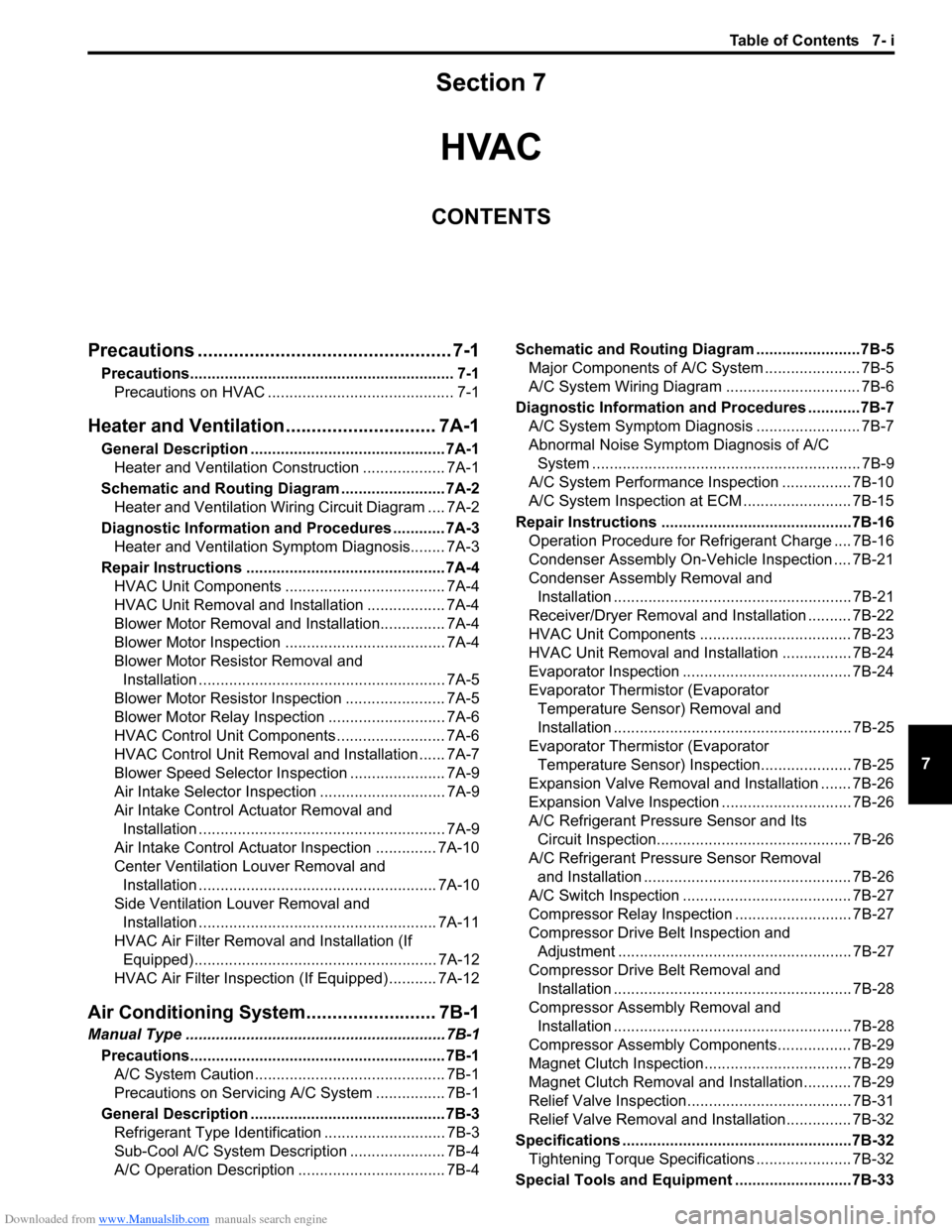
HVAC Air Filter Removal and Installation (If Equipped)........................................................ 7A-12
HVAC Air Filter Inspection (If Equipped) ........... 7A-12
Air Conditioning System... ...................... 7B-1
Manual Type ............................................................ 7B-1
Precautions........................................................... 7B-1A/C System Caution ............................................ 7B-1
Precautions on Servicing A/C System ................ 7B-1
General Description ............................................. 7B-3 Refrigerant Type Identifica tion ............................ 7B-3
Sub-Cool A/C System Description ...................... 7B-4
A/C Operation Description .................................. 7B-4 Schematic and Routing Diagram ........................7B-5
Major Components of A/C System ...................... 7B-5
A/C System Wiring Diagram ............................... 7B-6
Diagnostic Information and Procedures ............7B-7 A/C System Symptom Diagnosis ........................ 7B-7
Abnormal Noise Sympto m Diagnosis of A/C
System .............................................................. 7B-9
A/C System Performance Inspection ................ 7B-10
A/C System Inspection at ECM ......................... 7B-15
Repair Instructions ........... .................................7B-16
Operation Procedure for Re frigerant Charge .... 7B-16
Condenser Assembly On-Vehicle Inspection .... 7B-21
Condenser Assembly Removal and Installation ....................................................... 7B-21
Receiver/Dryer Removal and Installation .......... 7B-22
HVAC Unit Components ................................... 7B-23
HVAC Unit Removal and In stallation ................ 7B-24
Evaporator Inspection ....................................... 7B-24
Evaporator Thermistor (Evaporator Temperature Sensor) Removal and
Installation ....................................................... 7B-25
Evaporator Thermistor (Evaporator Temperature Sensor) Inspec tion..................... 7B-25
Expansion Valve Removal and Installation ....... 7B-26
Expansion Valve Inspection .............................. 7B-26
A/C Refrigerant Pressure Sensor and Its Circuit Inspection............................................. 7B-26
A/C Refrigerant Pressu re Sensor Removal
and Installation ................................................ 7B-26
A/C Switch Inspection ....................................... 7B-27
Compressor Relay Inspection ........................... 7B-27
Compressor Drive Belt Inspection and Adjustment ...................................................... 7B-27
Compressor Drive Belt Removal and Installation ....................................................... 7B-28
Compressor Assembly Removal and Installation ....................................................... 7B-28
Compressor Assembly Components................. 7B-29
Magnet Clutch Inspection.................................. 7B-29
Magnet Clutch Removal and Installation........... 7B-29
Relief Valve Inspection...................................... 7B-31
Relief Valve Removal and Installation............... 7B-32
Specifications .................... .................................7B-32
Tightening Torque Specifications ...................... 7B-32
Special Tools and Equipmen t ...........................7B-33
Page 948 of 1496
Downloaded from www.Manualslib.com manuals search engine 7A-12 Heater and Ventilation:
HVAC Air Filter Removal and Installation (If
Equipped)
S7RS0B7106016
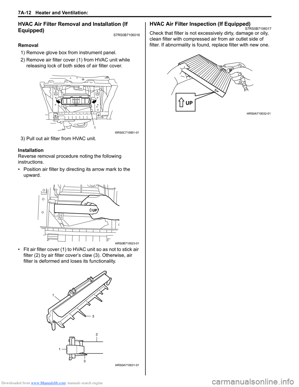
Removal1) Remove glove box from instrument panel.
2) Remove air filter cover (1) from HVAC unit while
releasing lock of both sides of air filter cover.
3) Pull out air filter from HVAC unit.
Installation
Reverse removal procedure noting the following
instructions.
• Position air filter by directing its arrow mark to the upward.
• Fit air filter cover (1) to HVAC unit so as not to stick air
filter (2) by air filter cove r’s claw (3). Otherwise, air
filter is deformed and loses its functionality.
HVAC Air Filter Inspection (If Equipped)S7RS0B7106017
Check that filter is not excessively dirty, damage or oily,
clean filter with compressed air from air outlet side of
filter. If abnormality is found, replace filter with new one.
1I5RS0C710001-01
I4RS0B710023-01
1
3
2
1
3I4RS0A710031-01
I4RS0A710032-01