2005 SUZUKI SWIFT starting
[x] Cancel search: startingPage 576 of 1496
Downloaded from www.Manualslib.com manuals search engine 4F-2 Electronic Stability Program:
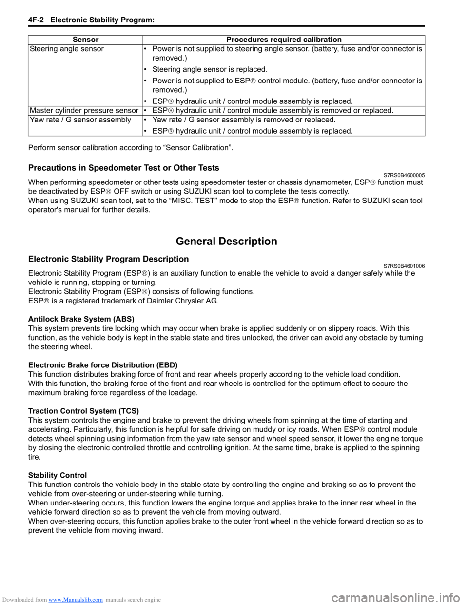
Perform sensor calibration according to “Sensor Calibration”.
Precautions in Speedometer Test or Other TestsS7RS0B4600005
When performing speedometer or other tests using speedometer tester or chassis dynamometer, ESP® function must
be deactivated by ESP ® OFF switch or using SUZUKI scan to ol to complete the tests correctly.
When using SUZUKI scan tool, set to the “MISC. TEST” mode to stop the ESP ® function. Refer to SUZUKI scan tool
operator's manual for further details.
General Description
Electronic Stability Program DescriptionS7RS0B4601006
Electronic Stability Program (ESP ®) is an auxiliary function to enable the vehicle to av oid a danger safely while the
vehicle is running, stopping or turning.
Electronic Stability Program (ESP ®) consists of following functions.
ESP ® is a registered trademark of Daimler Chrysler AG.
Antilock Brake System (ABS)
This system prevents tire locking which may occur when br ake is applied suddenly or on slippery roads. With this
function, as the vehicle body is kept in the stable state an d tires unlocked, the driver can avoid any obstacle by turning
the steering wheel.
Electronic Brake force Distribution (EBD)
This function distributes braking force of front and rear wheels properly according to the vehicle load condition.
With this function, the braking force of the front and rear wheels is controlled for the optimum effect to secure the
maximum braking force regardless of the loadage.
Traction Control System (TCS)
This system controls the engine and brake to prevent the dr iving wheels from spinning at the time of starting and
accelerating. Particularly, this fu nction is helpful for safe driving on muddy or icy roads. When ESP ® control module
detects wheel spinning using information from the yaw rate sensor and wheel speed sensor, it lower the engine torque
by closing the electronic controlled thro ttle and controlling ignition. At the same time, brake is applied to the spinning
tire.
Stability Control
This function controls the vehicle body in the stable state by controlling the engine and braking so as to prevent the
vehicle from over-steering or under-steering while turning.
When under-steering occurs, this function lowers the engine torque and applies brake to the inner rear wheel in the
vehicle forward direction so as to pr event the vehicle from moving outward.
When over-steering occurs, this function applies brake to the outer front wheel in the vehicle forward direction so as to
prevent the vehicle from moving inward. Sensor Procedures required calibration
Steering angle sensor • Power is not su pplied to steering angle sensor. (battery, fuse and/or connector is
removed.)
• Steering angle sensor is replaced.
• Power is not supplied to ESP ® control module. (battery, fuse and/or connector is
removed.)
• ESP® hydraulic unit / control module assembly is replaced.
Master cylinder pressure sensor • ESP® hydraulic unit / control module assembly is removed or replaced.
Yaw rate / G sensor assembly • Yaw rate / G sensor assembly is removed or replaced.
• ESP® hydraulic unit / control module assembly is replaced.
Page 589 of 1496
Downloaded from www.Manualslib.com manuals search engine Electronic Stability Program: 4F-15
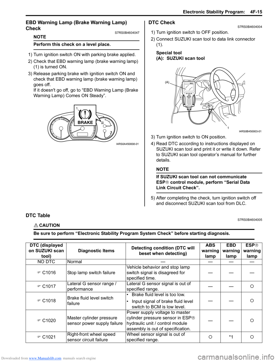
EBD Warning Lamp (Brake Warning Lamp)
Check
S7RS0B4604047
NOTE
Perform this check on a level place.
1) Turn ignition switch ON with parking brake applied.
2) Check that EBD warning lamp (brake warning lamp)
(1) is turned ON.
3) Release parking brake with ignition switch ON and check that EBD warning lamp (brake warning lamp)
goes off.
If it doesn't go off, go to “EBD Warning Lamp (Brake
Warning Lamp) Comes ON Steady”.
DTC CheckS7RS0B4604004
1) Turn ignition switch to OFF position.
2) Connect SUZUKI scan tool to data link connector (1).
Special tool
(A): SUZUKI scan tool
3) Turn ignition switch to ON position.
4) Read DTC according to instructions displayed on
SUZUKI scan tool and print it or write it down. Refer
to SUZUKI scan tool operator’s manual for further
details.
NOTE
If SUZUKI scan tool can not communicate
ESP® control module, perform “Serial Data
Link Circuit Check”.
5) After completing the check, turn ignition switch off and disconnect SUZUKI scan tool from DLC.
DTC TableS7RS0B4604005
CAUTION!
Be sure to perform “Electronic Stability Program System Check” before starting diagnosis.
BRAKE
1
I4RS0A450008-01
(A)
1
I4RS0B450003-01
DTC (displayed
on SUZUKI scan tool) Diagnostic Items
Detecting condition (DTC will
beset when detecting) ABS
warning lamp EBD
warning lamp ESP
®
warning lamp
NO DTC Normal — — — —
�) C1016 Stop lamp switch failure Vehicle behavior and stop lamp
switch signal is disagreed for
specified time.———
�) C1017 Lateral G sensor range /
performance Lateral G sensor signal is out of
specified range.
——
�{
�) C1018 Brake fluid level switch
failure • Brake fluid level is too low.
• Input signal of brake fluid level
switch to BCM is low level. ——
�{
�) C1020 Master cylinder pressure
sensor power supply failure Power supply volt
age to master
cylinder pressure sensor in ESP ®
hydraulic unit / control module
assembly is out of specification. ——
�{
�) C1021 Right-front wheel speed
sensor circuit failure Wheel sensor signal is out of
specified range.
�{
*1 �{
Page 693 of 1496

Downloaded from www.Manualslib.com manuals search engine Automatic Transmission/Transaxle: 5A-49
1) Connect scan tool to DLC with ignition switch OFF, if available.
2) Clear DTC in TCM memory and start engine.
3) Keep engine running at idle speed for 10 minutes or more.
4) Stop vehicle and check DTC.
DTC Troubleshooting
DTC P0713: Transmission Fluid Temperature Sensor “A” Circuit HighS7RS0B5104026
Wiring Diagram
DTC Detecting Condition and Trouble Area Step Action Yes No
1 Was “A/T System Check” performed? Go to Step 2. Go to “A/T System
Check”.
2 Check transmission fluid temperature circuit for ground
short
1) Check continuity between terminal “C34-11” of
disconnected harness side TCM connector and ground.
Is continuity indicated? “LT GRN” circuit shorted
to ground.
Go to Step 3.
3 Inspect transmission fluid temperature sensor
1) Inspect transmission fluid temperature sensor referring
to “Transmission Fluid Temperature Sensor Inspection”.
Is result satisfactory? Intermittent trouble or
faulty TCM. Check for
intermittent referring to
“Intermittent and Poor
Connection Inspection
in Section 00”. If OK,
substitute a known-
good TCM and recheck.Replace transmission
fluid temperature
sensor.
5V
C34-11
C34-12
LT G R N
ORN
2
3
12 11
C34C35
[A]
1
I4RS0A510011-01
1. TCM 3. A/T
2. Transmission fluid temperature sensor [A]: Terminal arrangement of TCM connector (viewed from harness side)
DTC detecting condition Trouble area
Transmission fluid temperature sensor terminal voltage is
more than specified value and sensor variation is less than
specified value even though engine was running in “R”, “D”,
“3”, “2” or “L” range for 15 minutes after starting engine. • Transmission fluid temperature sensor or its circuit
malfunction
•TCM
Page 750 of 1496
Downloaded from www.Manualslib.com manuals search engine 5A-106 Automatic Transmission/Transaxle:
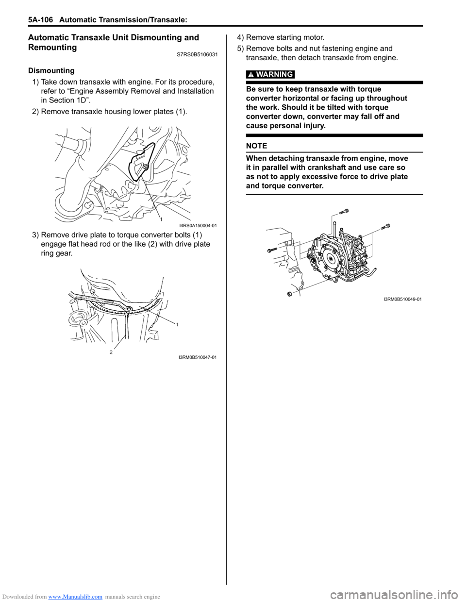
Automatic Transaxle Unit Dismounting and
Remounting
S7RS0B5106031
Dismounting1) Take down transaxle with engine. For its procedure, refer to “Engine Assembly Removal and Installation
in Section 1D”.
2) Remove transaxle housing lower plates (1).
3) Remove drive plate to torque converter bolts (1) engage flat head rod or the like (2) with drive plate
ring gear. 4) Remove starting motor.
5) Remove bolts and nut fastening engine and
transaxle, then detach transaxle from engine.WARNING!
Be sure to keep transaxle with torque
converter horizontal or facing up throughout
the work. Should it be tilted with torque
converter down, converter may fall off and
cause personal injury.
NOTE
When detaching transaxle from engine, move
it in parallel with cranks haft and use care so
as not to apply excessive force to drive plate
and torque converter.
1I4RS0A150004-01
I3RM0B510047-01
I3RM0B510049-01
Page 792 of 1496
Downloaded from www.Manualslib.com manuals search engine 5A-148 Automatic Transmission/Transaxle:
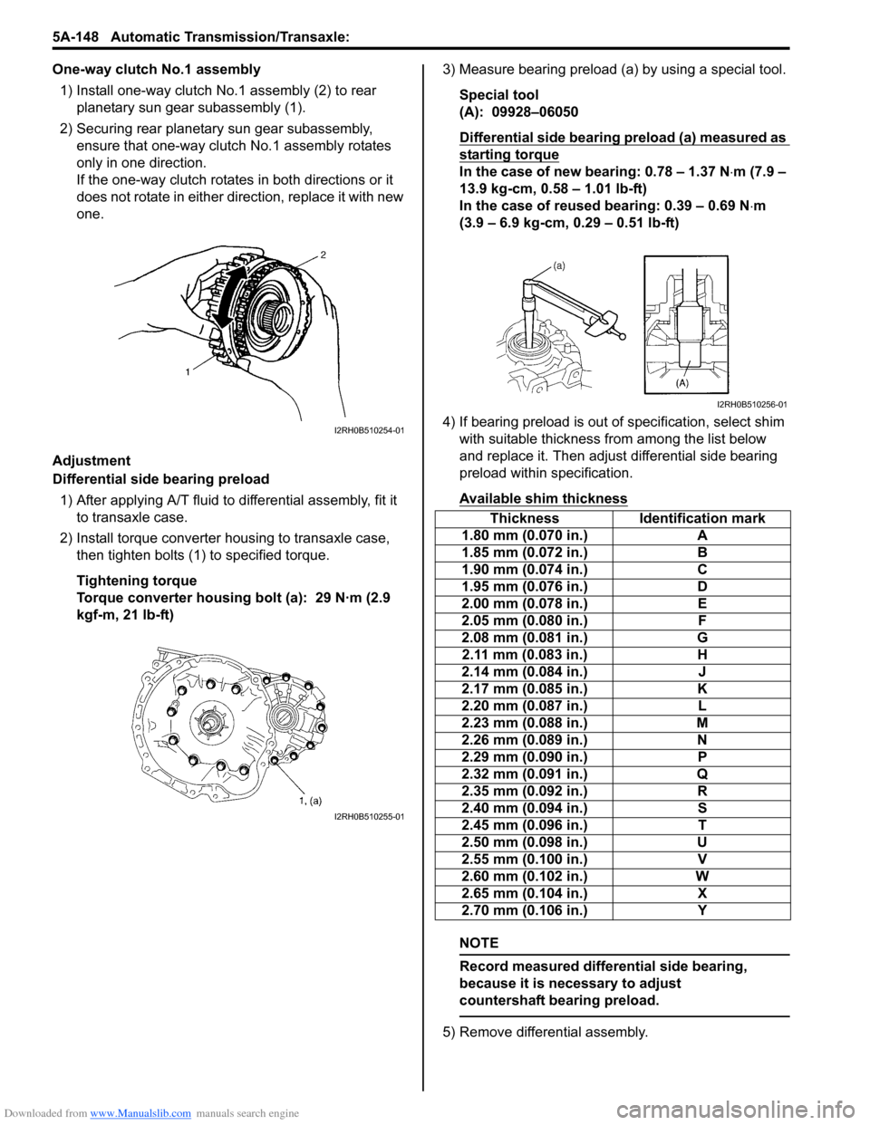
One-way clutch No.1 assembly1) Install one-way clutch No.1 assembly (2) to rear planetary sun gear subassembly (1).
2) Securing rear planetary sun gear subassembly, ensure that one-way clutch No.1 assembly rotates
only in one direction.
If the one-way clutch rotates in both directions or it
does not rotate in either direction, replace it with new
one.
Adjustment
Differential side bearing preload 1) After applying A/T fluid to differential assembly, fit it to transaxle case.
2) Install torque converter housing to transaxle case, then tighten bolts (1) to specified torque.
Tightening torque
Torque converter housing bolt (a): 29 N·m (2.9
kgf-m, 21 lb-ft) 3) Measure bearing preload (a) by using a special tool.
Special tool
(A): 09928–06050
Differential side bearing preload (a) measured as
starting torque
In the case of new bearing: 0.78 – 1.37 N ⋅m (7.9 –
13.9 kg-cm, 0.58 – 1.01 lb-ft)
In the case of reused bearing: 0.39 – 0.69 N ⋅m
(3.9 – 6.9 kg-cm, 0.29 – 0.51 lb-ft)
4) If bearing preload is out of specification, select shim with suitable thickness from among the list below
and replace it. Then adjust differential side bearing
preload within specification.
Available shim thickness
NOTE
Record measured differential side bearing,
because it is necessary to adjust
countershaft bearing preload.
5) Remove differential assembly.
I2RH0B510254-01
I2RH0B510255-01
Thickness Identification mark
1.80 mm (0.070 in.) A
1.85 mm (0.072 in.) B
1.90 mm (0.074 in.) C
1.95 mm (0.076 in.) D
2.00 mm (0.078 in.) E
2.05 mm (0.080 in.) F
2.08 mm (0.081 in.) G
2.11 mm (0.083 in.) H
2.14 mm (0.084 in.) J
2.17 mm (0.085 in.) K
2.20 mm (0.087 in.) L
2.23 mm (0.088 in.) M
2.26 mm (0.089 in.) N
2.29 mm (0.090 in.) P
2.32 mm (0.091 in.) Q
2.35 mm (0.092 in.) R
2.40 mm (0.094 in.) S
2.45 mm (0.096 in.) T
2.50 mm (0.098 in.) U
2.55 mm (0.100 in.) V
2.60 mm (0.102 in.) W
2.65 mm (0.104 in.) X
2.70 mm (0.106 in.) Y
I2RH0B510256-01
Page 793 of 1496
Downloaded from www.Manualslib.com manuals search engine Automatic Transmission/Transaxle: 5A-149
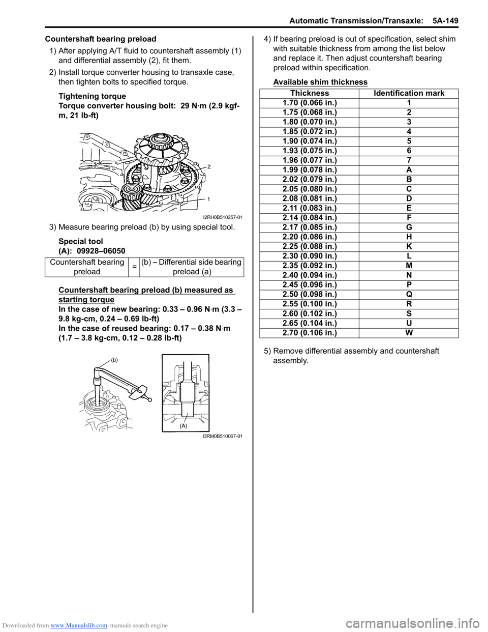
Countershaft bearing preload1) After applying A/T fluid to countershaft assembly (1) and differential assembly (2), fit them.
2) Install torque converter housing to transaxle case, then tighten bolts to specified torque.
Tightening torque
Torque converter housing bolt: 29 N·m (2.9 kgf-
m, 21 lb-ft)
3) Measure bearing preload (b) by using special tool. Special tool
(A): 09928–06050
Countershaft bearing preload (b) measured as
starting torque
In the case of new bearing: 0.33 – 0.96 N⋅ m (3.3 –
9.8 kg-cm, 0.24 – 0.69 lb-ft)
In the case of reused bearing: 0.17 – 0.38 N ⋅m
(1.7 – 3.8 kg-cm, 0.12 – 0.28 lb-ft) 4) If bearing preload is out of specification, select shim
with suitable thickness from among the list below
and replace it. Then adjust countershaft bearing
preload within specification.
Available shim thickness
5) Remove differential assembly and countershaft assembly.
Countershaft bearing
preload =(b) – Differential side bearing
preload (a)
I2RH0B510257-01
I3RM0B510067-01
Thickness Identification mark
1.70 (0.066 in.) 1
1.75 (0.068 in.) 2
1.80 (0.070 in.) 3
1.85 (0.072 in.) 4
1.90 (0.074 in.) 5
1.93 (0.075 in.) 6
1.96 (0.077 in.) 7
1.99 (0.078 in.) A
2.02 (0.079 in.) B
2.05 (0.080 in.) C
2.08 (0.081 in.) D
2.11 (0.083 in.) E
2.14 (0.084 in.) F
2.17 (0.085 in.) G
2.20 (0.086 in.) H
2.25 (0.088 in.) K
2.30 (0.090 in.) L
2.35 (0.092 in.) M
2.40 (0.094 in.) N
2.45 (0.096 in.) P
2.50 (0.098 in.) Q
2.55 (0.100 in.) R
2.60 (0.102 in.) S
2.65 (0.104 in.) U
2.70 (0.106 in.) W
Page 797 of 1496
Downloaded from www.Manualslib.com manuals search engine Automatic Transmission/Transaxle: 5A-153
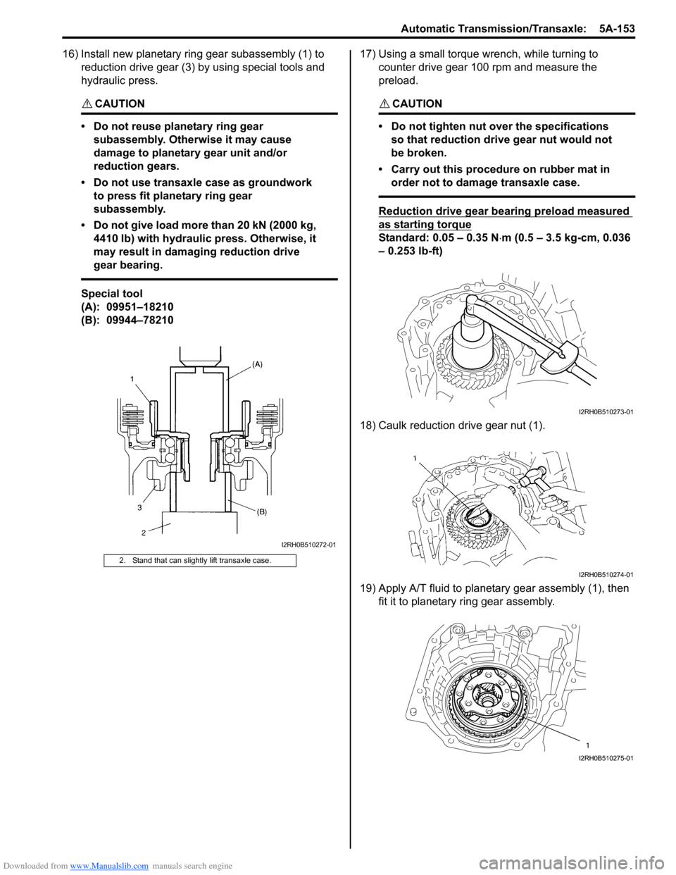
16) Install new planetary ring gear subassembly (1) to reduction drive gear (3) by using special tools and
hydraulic press.
CAUTION!
• Do not reuse planetary ring gear subassembly. Otherwise it may cause
damage to planetary gear unit and/or
reduction gears.
• Do not use transaxle case as groundwork to press fit planetary ring gear
subassembly.
• Do not give load more than 20 kN (2000 kg, 4410 lb) with hydraulic press. Otherwise, it
may result in damaging reduction drive
gear bearing.
Special tool
(A): 09951–18210
(B): 09944–78210 17) Using a small torque
wrench, while turning to
counter drive gear 100 rpm and measure the
preload.
CAUTION!
• Do not tighten nut over the specifications so that reduction drive gear nut would not
be broken.
• Carry out this procedure on rubber mat in order not to damage transaxle case.
Reduction drive gear bearing preload measured
as starting torque
Standard: 0.05 – 0.35 N ⋅m (0.5 – 3.5 kg-cm, 0.036
– 0.253 lb-ft)
18) Caulk reduction drive gear nut (1).
19) Apply A/T fluid to planetary gear assembly (1), then fit it to planetary ring gear assembly.
2. Stand that can slightly lift transaxle case.
I2RH0B510272-01
I2RH0B510273-01
I2RH0B510274-01
1
I2RH0B510275-01
Page 823 of 1496

Downloaded from www.Manualslib.com manuals search engine Manual Transmission/Transaxle: 5B-9
Manual Transaxle Unit Dismounting and
Remounting
S7RS0B5206009
Dismounting1) Drain coolant and transaxle oil.
2) Remove coolant reservoir with reservoir hose.
3) Remove battery and tray.
4) Remove air cleaner case and resonator.
5) Disconnect gear shift and gear select control cables (1) while pressing claws (2) of clip (3).
6) Disconnect back up light switch coupler and undo wiring harness clamps.
7) Remove ground cable from transaxle.
8) Remove clutch operating cylinder with fluid hose from transaxle.
9) Remove water inlet No.2 pipe from transaxle.
10) Remove starting motor re ferring to “Starting Motor
Dismounting and Remounting in Section 1I”.
11) Remove transaxle to engine bolts (1) of upper side. 12) Support engine using supporting device (1).
CAUTION!
Do not apply supporting device to projection
part A. If do so, it may be deformed.
13) Remove front drive shafts and center shaft referring
to “Front Drive Shaft Assembly Removal and
Installation in Section 3A”.
14) Remove exhaust No.2 pipe referring to “Exhaust Pipe and Muffler Removal a nd Installation in Section
1K”.
15) Remove clutch housing lower plate (1).
1
2
3
I7RS0A521003-01
1
1
I4RS0A520018-01
1
A
I4RS0A520019-01
1I4RS0A520020-01