2005 SUZUKI SWIFT Full manuals
[x] Cancel search: Full manualsPage 483 of 1496
Downloaded from www.Manualslib.com manuals search engine Drive Shaft / Axle: 3A-5
8) Disconnect front suspension control arm ball joint
stud from steering knuckle.
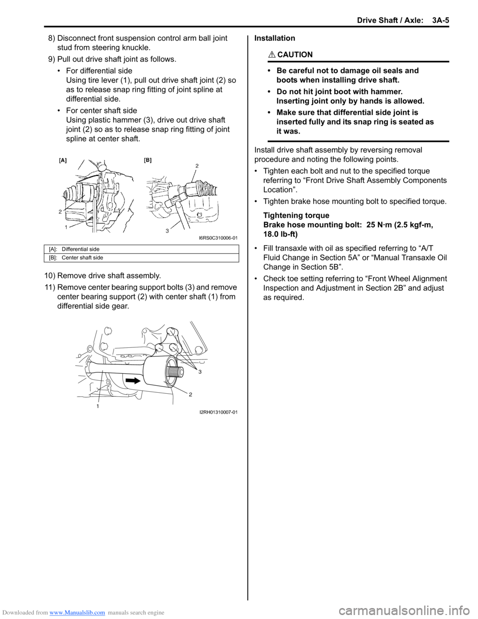
9) Pull out drive shaft joint as follows. • For differential sideUsing tire lever (1), pull out drive shaft joint (2) so
as to release snap ring fitting of joint spline at
differential side.
• For center shaft side Using plastic hammer (3), drive out drive shaft
joint (2) so as to release snap ring fitting of joint
spline at center shaft.
10) Remove drive shaft assembly. 11) Remove center bearing support bolts (3) and remove center bearing support (2) with center shaft (1) from
differential side gear. Installation
CAUTION!
• Be careful not to damage oil seals and
boots when installing drive shaft.
• Do not hit joint boot with hammer. Inserting joint only by hands is allowed.
• Make sure that differential side joint is inserted fully and its snap ring is seated as
it was.
Install drive shaft assemb ly by reversing removal
procedure and noting the following points.
• Tighten each bolt and nut to the specified torque referring to “Front Drive Shaft Assembly Components
Location”.
• Tighten brake hose mounting bolt to specified torque.
Tightening torque
Brake hose mounting bolt: 25 N·m (2.5 kgf-m,
18.0 lb-ft)
• Fill transaxle with oil as sp ecified referring to “A/T
Fluid Change in Section 5A” or “Manual Transaxle Oil
Change in Section 5B”.
• Check toe setting referring to “Front Wheel Alignment Inspection and Adjustment in Section 2B” and adjust
as required.
[A]: Differential side
[B]: Center shaft side
I6RS0C310006-01
3
2
1I2RH01310007-01
Page 486 of 1496
Downloaded from www.Manualslib.com manuals search engine 3A-8 Drive Shaft / Axle:
Reassembly
Tripod joint
Judging from abnormality noted before disassembly and
what is found through visual check of component parts
after disassembly, prepare replacing parts and proceed
to reassembly.
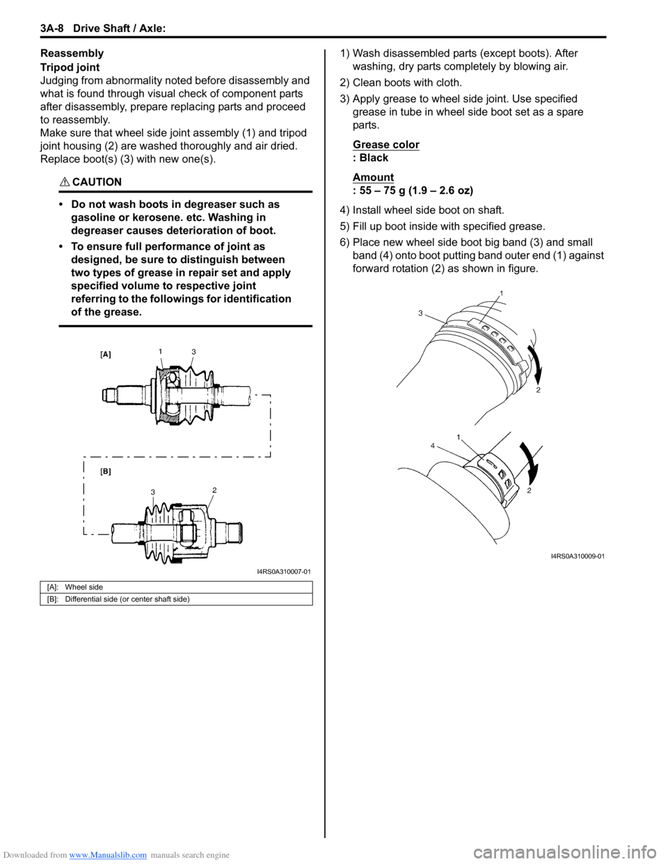
Make sure that wheel side joint assembly (1) and tripod
joint housing (2) are washed thoroughly and air dried.
Replace boot(s) (3) with new one(s).
CAUTION!
• Do not wash boots in degreaser such as gasoline or kerosene. etc. Washing in
degreaser causes deterioration of boot.
• To ensure full performance of joint as designed, be sure to distinguish between
two types of grease in repair set and apply
specified volume to respective joint
referring to the followings for identification
of the grease.
1) Wash disassembled parts (except boots). After washing, dry parts comp letely by blowing air.
2) Clean boots with cloth.
3) Apply grease to wheel side joint. Use specified grease in tube in wheel side boot set as a spare
parts.
Grease color
: Black
Amount
: 55 – 75 g (1.9 – 2.6 oz)
4) Install wheel side boot on shaft.
5) Fill up boot inside with specified grease.
6) Place new wheel side boot big band (3) and small band (4) onto boot putting band outer end (1) against
forward rotation (2) as shown in figure.
[A]: Wheel side
[B]: Differential side (or center shaft side)
I4RS0A310007-01
I4RS0A310009-01
Page 489 of 1496
Downloaded from www.Manualslib.com manuals search engine Drive Shaft / Axle: 3A-11
DOJ
Judging from abnormality noted before disassembly and
what is found through visual check of components parts
after disassembly, prepare replacing parts and proceed
to reassembly.
Make sure that wheel side joint assembly and DOJ
housing are washed thoroughly and air dried.
Replace boot(s) with new one(s).
CAUTION!
• Do not wash boots in degreaser such as gasoline or kerosene. etc. Washing in
degreaser causes deterioration of boot.
• To ensure full performance of joint as designed, be sure to distinguish between
two types of grease in repair set and apply
specified volume to respective joint
referring to the followings for identification
of the grease.
1) Wash disassembled parts (except boots). After washing, dry parts completely by blowing air.
2) Clean boots with cloth.
3) Apply grease to wheel side joint. Use specified
grease in tube in wheel side boot set as a spare
parts.
Grease color
: Black
Amount
: 55 – 75 g (1.9 – 2.6 oz)
4) Install wheel side boot on shaft.
5) Fill up boot inside wi th specified grease.
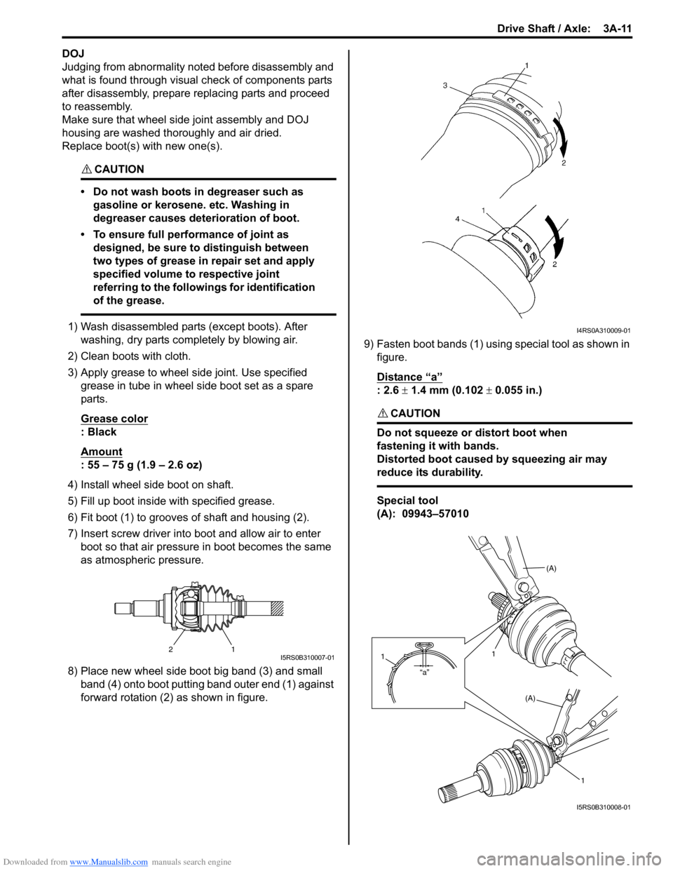
6) Fit boot (1) to grooves of shaft and housing (2).
7) Insert screw driver into boot and allow air to enter boot so that air pressure in boot becomes the same
as atmospheric pressure.
8) Place new wheel side boot big band (3) and small band (4) onto boot putting band outer end (1) against
forward rotation (2) as shown in figure. 9) Fasten boot bands (1) using special tool as shown in
figure.
Distance “a”
: 2.6 ± 1.4 mm (0.102 ± 0.055 in.)
CAUTION!
Do not squeeze or distort boot when
fastening it with bands.
Distorted boot caused by squeezing air may
reduce its durability.
Special tool
(A): 09943–57010
21I5RS0B310007-01
I4RS0A310009-01
(A)
1
(A)
1
“a”
1
I5RS0B310008-01
Page 507 of 1496
Downloaded from www.Manualslib.com manuals search engine Brake Control System and Diagnosis: 4A-9
Air Bleeding of Brake SystemS7RS0B4106006
CAUTION!
Brake fluid is extremely damaging to paint. If
fluid should accidentally touch painted
surface, immediately wipe fluid from paint
and clean painted surface.
Bleeding operation is necessary to remove air whenever
it entered hydraulic brake system.
Hydraulic lines of brake system are based on the
diagonal split system. When a brake pipe or hose was
disconnected at the wheel, bleeding operation must be
performed at both ends of the line of the removed pipe or
hose. When any joint part of the master cylinder of other
joint part between the master cylinder and each brake
(wheel) was removed, the hydraulic brake system must
be bled at all 4 wheel brakes.
NOTE
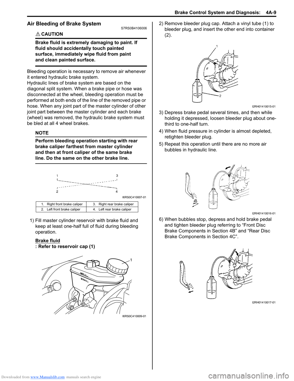
Perform bleeding operation starting with rear
brake caliper farthest from master cylinder
and then at front caliper of the same brake
line. Do the same on the other brake line.
1) Fill master cylinder rese rvoir with brake fluid and
keep at least one-half full of fluid during bleeding
operation.
Brake fluid
: Refer to reservoir cap (1) 2) Remove bleeder plug cap. Attach a vinyl tube (1) to
bleeder plug, and insert the other end into container
(2).
3) Depress brake pedal several times, and then while holding it depressed, loosen bleeder plug about one-
third to one-half turn.
4) When fluid pressure in cy linder is almost depleted,
retighten bleeder plug.
5) Repeat this operation until there are no more air bubbles in hydraulic line.
6) When bubbles stop, depress and hold brake pedal and tighten bleeder plug referring to “Front Disc
Brake Components in Section 4B” and “Rear Disc
Brake Components in Section 4C”.
1. Right front brake caliper 3. Right rear brake caliper
2. Left front brake caliper 4. Left rear brake caliper
I6RS0C410007-01
1
I6RS0C410009-01
I2RH01410015-01
I2RH01410016-01
I2RH01410017-01
Page 537 of 1496
Downloaded from www.Manualslib.com manuals search engine Parking Brake: 4D-2
Repair Instructions
Parking Brake Inspection and AdjustmentS7RS0B4406001
Inspection
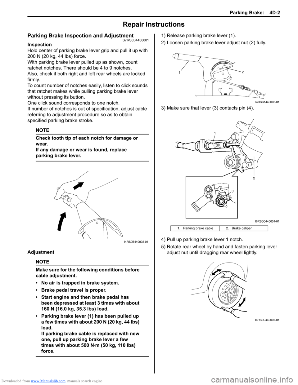
Hold center of parking brake lever grip and pull it up with
200 N (20 kg, 44 lbs) force.
With parking brake lever pulled up as shown, count
ratchet notches. There should be 4 to 9 notches.
Also, check if both right and left rear wheels are locked
firmly.
To count number of notches easily, listen to click sounds
that ratchet makes while pulling parking brake lever
without pressing its button.
One click sound corresponds to one notch.
If number of notches is out of specification, adjust cable
referring to adjustment procedure so as to obtain
specified parking brake stroke.
NOTE
Check tooth tip of each notch for damage or
wear.
If any damage or wear is found, replace
parking brake lever.
Adjustment
NOTE
Make sure for the following conditions before
cable adjustment.
• No air is trapped in brake system.
• Brake pedal travel is proper.
• Start engine and then brake pedal has been depressed at least 3 times with about
160 N (16.0 kg, 35.3 lbs) load.
• Parking brake lever (1) has been pulled up a few times with about 200 N (20 kg, 44 lbs)
load.
If parking brake cable is replaced with new
one, pull up parking brake lever a few
times with about 500 N ⋅m (50 kg, 110 lbs)
force.
1) Release parking brake lever (1).
2) Loosen parking brake lever adjust nut (2) fully.
3) Make sure that lever (3) contacts pin (4).
4) Pull up parking brake lever 1 notch.
5) Rotate rear wheel by hand and fasten parking lever adjust nut until dragging rear wheel lightly.
I4RS0B440002-01
1. Parking brake cable 2. Brake caliper
I4RS0A440003-01
I6RS0C440001-01
I6RS0C440002-01
Page 540 of 1496
Downloaded from www.Manualslib.com manuals search engine 4E-1 ABS:
Brakes
ABS
Precautions
Precautions in Diagnosing TroublesS7RS0B4500001
To ensure that the trouble diagnosis is done accurately
and smoothly, observe the following and follow “ABS
Check”.
• Diagnostic information stored in ABS cont rol module
memory can be cleared as well as checked by using
SUZUKI scan tool. Before us ing scan tool, read its
Operator’s (Instruction) Manual carefully to have good
understanding as to what functions are available and
how to use it.
• If the vehicles was operated in any of the following ways, ABS warning light may light momentarily but
this does not indicate anything abnormal in ABS.
– The vehicle was driven with parking brake pulled.
– The vehicle was driven with brake dragging.
– The vehicle was stuck in mud, sand, etc.
– Wheel spin occurred while driving.
– Wheel(s) was rotated while the vehicle was jacked up.
• Be sure to read “Precautions for Electrical Circuit Service in Section 00” befo re inspection and observe
what is written there.
• Be sure to use the trouble diagnosis procedure as described in “ABS Check”. Failure to follow it may
result in incorrect diagnosis. (Some other diagnosis
trouble code may be stored by mistake in the memory
of ABS control module during inspection.)
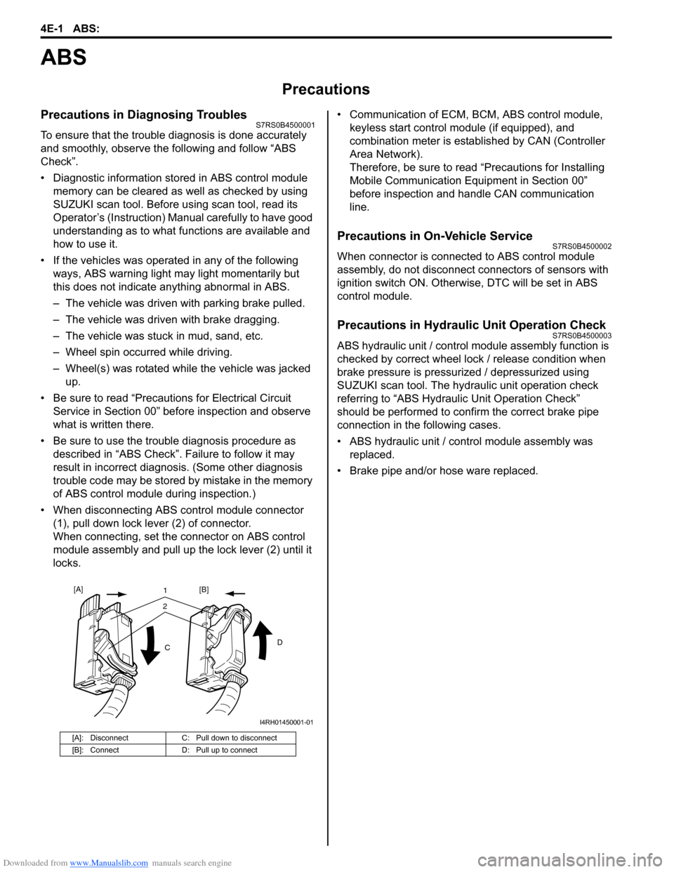
• When disconnecting ABS co ntrol module connector
(1), pull down lock lever (2) of connector.
When connecting, set the connector on ABS control
module assembly and pull up the lock lever (2) until it
locks. • Communication of ECM,
BCM, ABS control module,
keyless start control module (if equipped), and
combination meter is established by CAN (Controller
Area Network).
Therefore, be sure to read “Precautions for Installing
Mobile Communication Equipment in Section 00”
before inspection and handle CAN communication
line.
Precautions in On-Vehicle ServiceS7RS0B4500002
When connector is connected to ABS control module
assembly, do not disconnect connectors of sensors with
ignition switch ON. Otherwise, DTC will be set in ABS
control module.
Precautions in Hydraulic Unit Operation CheckS7RS0B4500003
ABS hydraulic unit / control module assembly function is
checked by correct wheel lock / release condition when
brake pressure is pressurized / depressurized using
SUZUKI scan tool. The hydraulic unit operation check
referring to “ABS Hydraulic Unit Operation Check”
should be performed to confirm the correct brake pipe
connection in the following cases.
• ABS hydraulic unit / cont rol module assembly was
replaced.
• Brake pipe and/or hose ware replaced.
[A]: Disconnect C: Pull down to disconnect
[B]: Connect D: Pull up to connect
21
C D
[A]
[B]
I4RH01450001-01
Page 575 of 1496
Downloaded from www.Manualslib.com manuals search engine Electronic Stability Program: 4F-1
Brakes
Electronic Stability Program
Precautions
Precautions in Diagnosing TroublesS7RS0B4600001
To ensure that the trouble diagnosis is done accurately
and smoothly, observe the following and follow
“Electronic Stability Program System Check”.
• Diagnostic information stored in ESP® control module
memory can be cleared as well as checked by using
SUZUKI scan tool. Before us ing scan tool, read its
Operator’s (Instruction) Manual carefully to have good
understanding as to what functions are available and
how to use it.
• If the vehicles was operated in any of the following ways, ESP ® warning lamp may light momentarily but
this does not indicate anything abnormal in ESP ®.
– The vehicle was driven with parking brake pulled.
– The vehicle was driven with brake dragging.
– The vehicle was stuck in mud, sand, etc.
– Wheel spin occurred while driving.
– Wheel(s) was rotated while the vehicle was jacked up.
• Be sure to use the trouble diagnosis procedure as described in “Electronic Stability Program System
Check”. Failure to follow it may resu lt in incorrect
diagnosis. (Some other diagnosis trouble code may
be stored by mistake in the memory of ESP ® control
module during inspection.)
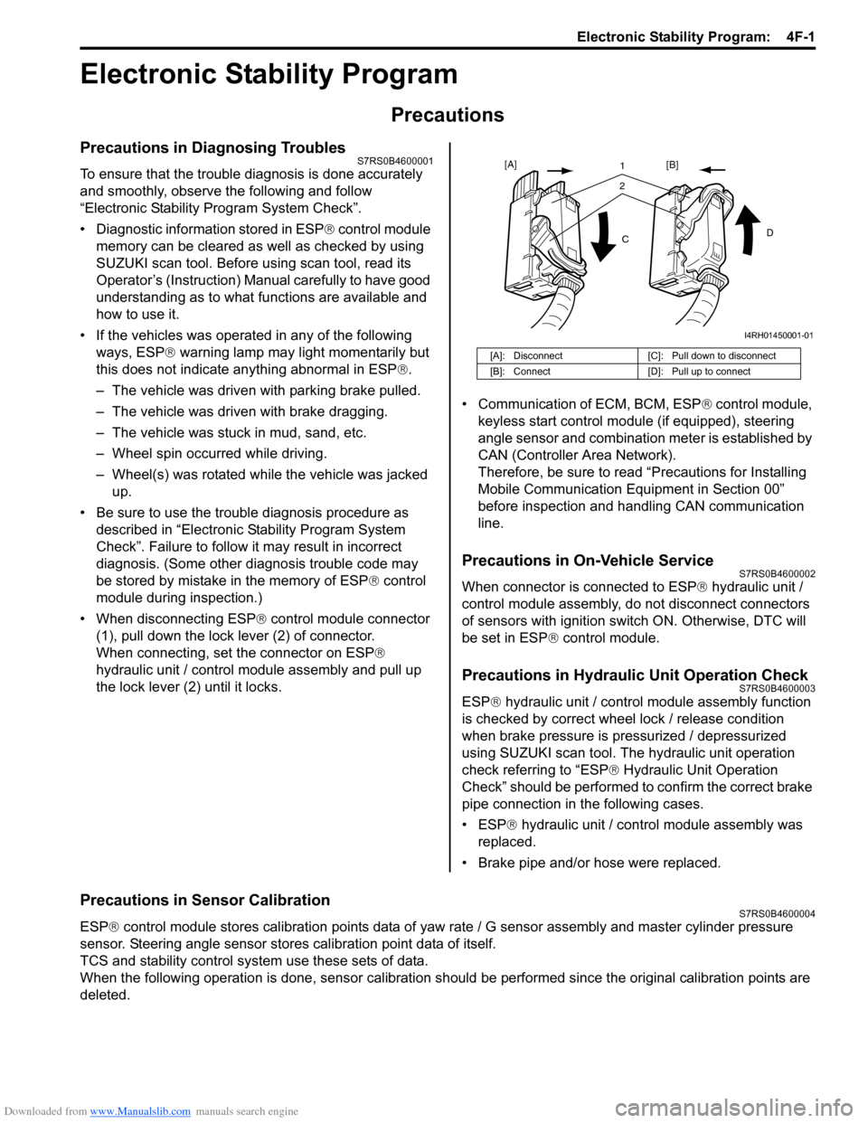
• When disconnecting ESP ® control module connector
(1), pull down the lock lever (2) of connector.
When connecting, set the connector on ESP ®
hydraulic unit / control module assembly and pull up
the lock lever (2) until it locks. • Communication of ECM, BCM, ESP
® control module,
keyless start control module (if equipped), steering
angle sensor and combination meter is established by
CAN (Controller Area Network).
Therefore, be sure to read “Precautions for Installing
Mobile Communication Equipment in Section 00”
before inspection and handling CAN communication
line.
Precautions in On-Vehicle ServiceS7RS0B4600002
When connector is connected to ESP ® hydraulic unit /
control module assembly, do not disconnect connectors
of sensors with ignition switch ON. Otherwise, DTC will
be set in ESP ® control module.
Precautions in Hydraulic Unit Operation CheckS7RS0B4600003
ESP® hydraulic unit / control module assembly function
is checked by correct wheel lock / release condition
when brake pressure is pressurized / depressurized
using SUZUKI scan tool. The hydraulic unit operation
check referring to “ESP ® Hydraulic Unit Operation
Check” should be performed to confirm the correct brake
pipe connection in the following cases.
• ESP® hydraulic unit / contro l module assembly was
replaced.
• Brake pipe and/or hose were replaced.
Precautions in Sensor CalibrationS7RS0B4600004
ESP ® control module stores calibration points data of yaw rate / G sensor assembly and master cylinder pressure
sensor. Steering angle sensor stores calibration point data of itself.
TCS and stability control system use these sets of data.
When the following operation is done, sensor calibration should be performed since the original calibration points are
deleted.
[A]: Disconnect [C]: Pull down to disconnect
[B]: Connect [D]: Pull up to connect
21
C D
[A]
[B]
I4RH01450001-01
Page 637 of 1496
Downloaded from www.Manualslib.com manuals search engine Electronic Stability Program: 4F-63
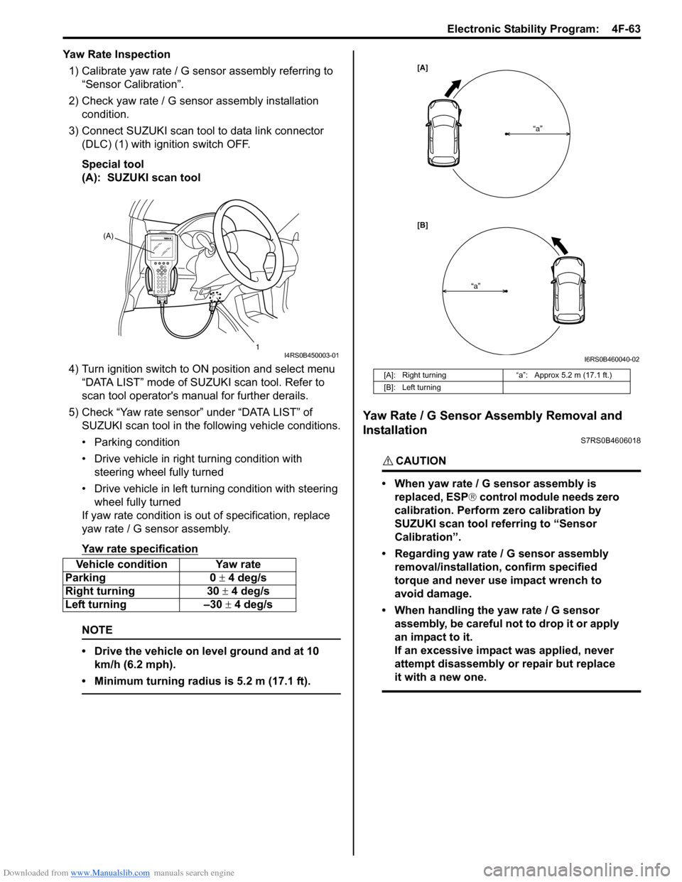
Yaw Rate Inspection1) Calibrate yaw rate / G sens or assembly referring to
“Sensor Calibration”.
2) Check yaw rate / G sensor assembly installation
condition.
3) Connect SUZUKI scan tool to data link connector (DLC) (1) with ignition switch OFF.
Special tool
(A): SUZUKI scan tool
4) Turn ignition switch to ON position and select menu
“DATA LIST” mode of SUZUKI scan tool. Refer to
scan tool operator's manual for further derails.
5) Check “Yaw rate sensor” under “DATA LIST” of SUZUKI scan tool in the following vehicle conditions.
• Parking condition
• Drive vehicle in right turning condition with steering wheel fully turned
• Drive vehicle in left tu rning condition with steering
wheel fully turned
If yaw rate condition is ou t of specification, replace
yaw rate / G sensor assembly.
Yaw rate specification
NOTE
• Drive the vehicle on level ground and at 10 km/h (6.2 mph).
• Minimum turning radius is 5.2 m (17.1 ft).
Yaw Rate / G Sensor Assembly Removal and
Installation
S7RS0B4606018
CAUTION!
• When yaw rate / G sensor assembly is replaced, ESP ® control module needs zero
calibration. Perform zero calibration by
SUZUKI scan tool referring to “Sensor
Calibration”.
• Regarding yaw rate / G sensor assembly removal/installation, confirm specified
torque and never use impact wrench to
avoid damage.
• When handling the yaw rate / G sensor assembly, be careful not to drop it or apply
an impact to it.
If an excessive impact was applied, never
attempt disassembly or repair but replace
it with a new one.
Vehicle condition Yaw rate
Parking 0 ± 4 deg/s
Right turning 30 ± 4 deg/s
Left turning –30 ± 4 deg/s
(A)
1
I4RS0B450003-01
[A]: Right turning“a”: Approx 5.2 m (17.1 ft.)
[B]: Left turning
[A]
[B] “a”
“a”
I6RS0B460040-02