Page 1256 of 1496
Downloaded from www.Manualslib.com manuals search engine 9A-85 Wiring Systems:
D-7 Brake Light System Circuit DiagramS7RS0B910E028
Brakelight
switch
(R)
Brake light
PNK
BLK
(L)
15A
8STOP
LAMP
E47
L43
GRN/WHT
GRN/WHT
GRN/WHT
5
4
1
L0628
E411
J/B
"F-2"
ABS
Cont.M
GRN/WHT
2
"A-5"
ECM
13
GW
GWGW
TCM
PB
PNK/BLK
"A-6"
GRN/YEL
A/T shift
lever
GY
"A-6"
2 3
A/T
18
Individual circuit
fuse box (No.1)
B
BL74
J/C
L202
5L172
1
High mounted stop light
14
BLK
BLK
2
B
GRN/WHTGRN/WHT
I7RS0B910929-01
Page 1257 of 1496
Downloaded from www.Manualslib.com manuals search engine Wiring Systems: 9A-86
D-8 Back-Up Light System Circuit DiagramS7RS0B910E029
BLKBLK
141313
CC
C
J/C
L74CL28
Back-up light
switch
Back-up light (R)
RED
RED
RED/BLK
RED/BLK
ON
OFF J/B
10A
24BACK
E24
C3619
C302
1 20
L431L201
RED
RED
RED
M/T
L063
E4111
J/B
P R N D2LTransaxle
range sensor
RED/BLK
C28
R
RED
8
RED
"A-6"
TCM
R
E4114
7
5 5
Reverse signal pick-up
(For optional navigation)
5RED
(L)
Back-uplight (R)
(L)
M13A engine, M15A engine M16A engine
BLK
BLK
BLKBLK
F
M042
RED
REDRED
REDRED
1
M052
1
1L70
M012
3
A/T
I7RS0B910930-01
Page 1258 of 1496
Downloaded from www.Manualslib.com manuals search engine 9A-87 Wiring Systems:
D-9 Headlight Beam Leveling System Circuit DiagramS7RS0B910E030
10A
RED/BLK
GRN
GRN
RED/BLKRED/BLK
GRN
BLK
BLKBLK
switch
24BACK
RED/BLKRED/BLK
E59
G343E583
1
8E4114
12
G40 E38
G3653
4 10
G36
E3820 2
BLKBLK
Actuator (L)
Actuator (R)
R1
P0
P1
P2
P3
P4
R2
R3
R4
R5
R6
J/B
57
B
B
J/C
G31
I7RS0B910944-01
Page 1259 of 1496
Downloaded from www.Manualslib.com manuals search engine Wiring Systems: 9A-88
D-10 Rear Fog Light Circuit DiagramS7RS0B910E031
15ARR
FOG
BLK
BLU/ORN
BLU/ORN
YEL/BLK
OFF
ON
L60
12
"C-2"
BO
G253
G3410
4
J/B
13
G03 L336
39
Switch
I5RS0C910950-02
Page 1266 of 1496
Downloaded from www.Manualslib.com manuals search engine 9A-95 Wiring Systems:
F-2 Anti-Lock Brake System Circuit DiagramS7RS0B910E035
1326
14
1 3
23
17
E03
ABS
Cont.M
BCM
BLK
30A
ABS
SOL16
30A
ABS
MOT9
WHT/REDWHT/BLU
GRN/WHT
6
BLKREDWHT
PNK/BLK
PB
PNK/BLK
RB
RED/BLU
RED/BLU
149G35 E37
"C-3""A-8"
ECM
"A-5"
J/B10A ABS
31
E419
GRN/ORN
7
GW"D-7"Brake light switch
(CAN)
(CAN)
(ABS)
GRN/WHT
J/B
E411
8
Individual circuit fuse box (No.1)
108
12
RED
R
6
WHT
W
RW
M13A engine, M15A engine
M16A engineA
AB
B
I7RS0B910933-01
Page 1268 of 1496
Downloaded from www.Manualslib.com manuals search engine 9A-97 Wiring Systems:
F-3 Electronic Stability Program System Circuit DiagramS7RS0B910E039
1647
132 13
44E85
BLK
ABS
SOLABS
MOT
WHT/REDWHT/BLU
6
BLK
REDWHT
REDWHT
REDWHT
25
BLK/ORN
GRN/ORN
GRN/ORN
GRN/ORN
Individual circuit
fuse box (No.1) J/B
ABS
GRN/ORN
ECM
35
"A-5"
"C-3"
steering
angle sensor
RED
R
4246
WHT
W
RW
1
4G37
E46
2
2
BCM
A
A
A
BG59
B
B
RW
2
1
WHT/REDWHTRED
3910
(CAN) (CAN)
(CAN)
(CAN)
(CAN)
7
ESP
Cont.M
1E45 L02
LT GRN/RED
LT GRN/REDRED/YEL
RED/YEL
BLK/ORN
WHT/BLK
RY
J/C J/C
B
BLKBLK
BLK/ORN
BLK/ORN
16181410
BLK
ESP off
switch
L6956
42
G15
G541
29
RED/BLK
2
37
BLU/RED
3
31
GRN/BLK
5E84B
J/C
D
L74D
R
R
"D-3"J/B
YAW/G sensor
J/C
A
L24A
B
B
30A
16
40A
9
10A
31
15A
RADIO
40
E419G335
E37
G3514
I7RS0B910935-01
Page 1272 of 1496
Downloaded from www.Manualslib.com manuals search engine 9A-101 Wiring Systems:
G-1 Audio System Circuit DiagramS7RS0B910E037
PPL
PPL
G335
GRY
18141814L37J21
G03 L333 13 2
515 14
4 5
4
5
11
21 1
2 2
1 1
2 2
1 2
1
3
13 4
14 5
15 6
16 11
RY"D-4"RY
WHT/RED
G121
J/C
G17
WHT/RED
J/B15ARADIO
40
RED/YEL
J/C
G31
BCM
"A-8"
Antenna amplifier
WHT/GRN
L39
L33
G0318E37
G354
WHT/GRN
BLU/WHT
BLU/WHT
15A ACC 2
27
BLK
10
Tweeter (L)Front (L)
PNKBLU
J12
J10
Tweeter (R)Front (R)
J04J02
YEL/BLK
YEL/RED
Rear (R)Rear (L)
LT GRN
LT GRN/BLKPNKBLUPNKBLUYEL/BLK
YEL/RED
YEL/BLK
YEL/REDLT GRN
LT GRN/BLK
GRY/RED
GRY
GRY/RED
PNKBLUYEL/BLK
YEL/REDLT GRN
LT GRN/BLKGRY
GRY/RED
12
Audio
RED/YEL
921 0
J22J17
B
B C
C D
DSteering switch
(volume/seek etc)
G27
GRN
1920
BLK/YEL
4 3
L13
J16
4
P
ECM
"A-5"
18
RHD
LHD
Other than indonesian make
Indonesian make
ABC
DC
D
Antenna
L31
J09
L07 J01A
B
L07 J01
L31 J09A
B
IF EQPD
I7RS0B910938-01
Page 1283 of 1496

Downloaded from www.Manualslib.com manuals search engine Lighting Systems: 9B-1
Body, Cab and Accessories
Lighting Systems
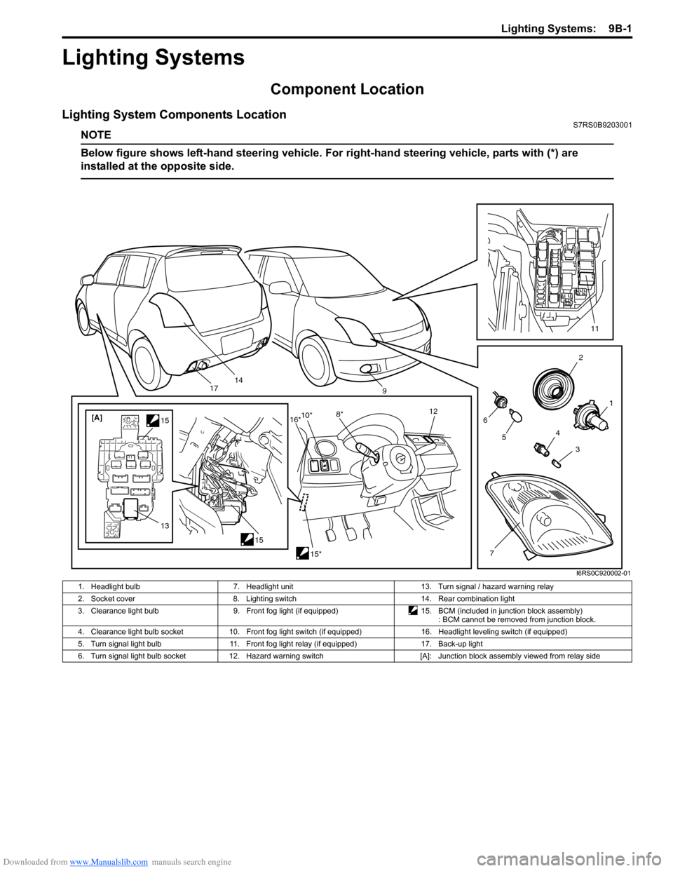
Component Location
Lighting System Components LocationS7RS0B9203001
NOTE
Below figure shows left-hand steering vehicle. For right-hand steering vehicle, parts with (*) are
installed at the opposite side.
2
1
3
4
6
14
5
7
11
9
15
[A]
1515*
10*
8* 12
13
16*
17
I6RS0C920002-01
1. Headlight bulb 7. Headlight unit 13. Turn signal / hazard warning relay
2. Socket cover 8. Lighting switch 14. Rear combination light
3. Clearance light bulb 9. Front fog light (if equipped)15. BCM (included in junction block assembly)
: BCM cannot be removed from junction block.
4. Clearance light bulb socket 10. Front fog light switch (if equipped) 16. Headlight leveling switch (if equipped)
5. Turn signal light bulb 11. Front fog light relay (if equipped) 17. Back-up light
6. Turn signal light bulb socket 12. Hazard warning switch [A]: Junction block assembly viewed from relay side