2005 SUZUKI SWIFT radiator
[x] Cancel search: radiatorPage 963 of 1496
Downloaded from www.Manualslib.com manuals search engine Air Conditioning System: Manual Type 7B-15
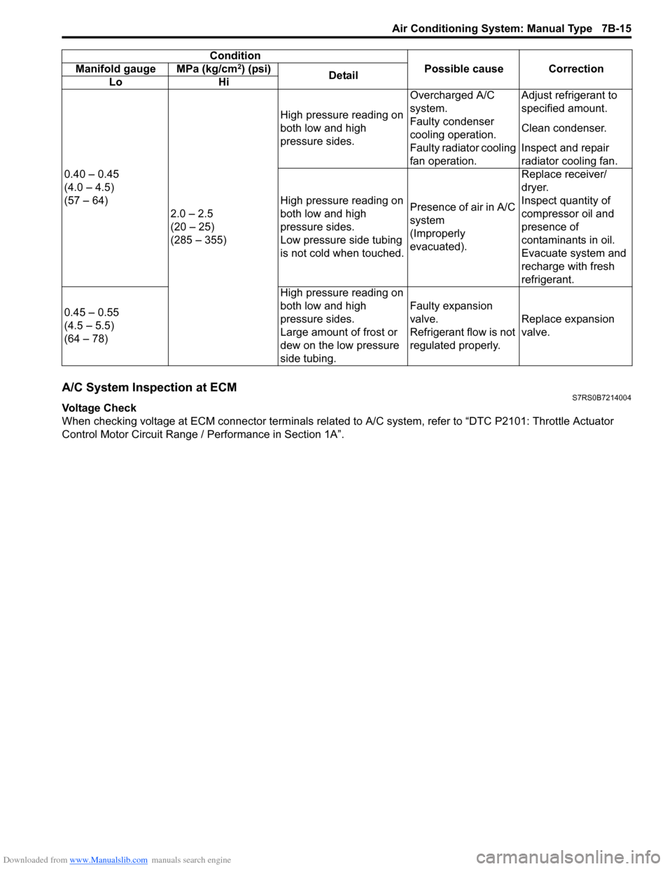
A/C System Inspection at ECMS7RS0B7214004
Voltage Check
When checking voltage at ECM connector terminals related to A/C system, refer to “DTC P2101: Throttle Actuator
Control Motor Circuit Range / Performance in Section 1A”.
0.40 – 0.45
(4.0 – 4.5)
(57 – 64)
2.0 – 2.5
(20 – 25)
(285 – 355) High pressure reading on
both low and high
pressure sides.
Overcharged A/C
system.
Adjust refrigerant to
specified amount.
Faulty condenser
cooling operation. Clean condenser.
Faulty radiator cooling
fan operation. Inspect and repair
radiator cooling fan.
High pressure reading on
both low and high
pressure sides.
Low pressure side tubing
is not cold when touched. Presence of air in A/C
system
(Improperly
evacuated).Replace receiver/
dryer.
Inspect quantity of
compressor oil and
presence of
contaminants in oil.
Evacuate system and
recharge with fresh
refrigerant.
0.45 – 0.55
(4.5 – 5.5)
(64 – 78) High pressure reading on
both low and high
pressure sides.
Large amount of frost or
dew on the low pressure
side tubing.Faulty expansion
valve.
Refrigerant flow is not
regulated properly.
Replace expansion
valve.
Condition
Possible cause Correction
Manifold gauge MPa (kg/cm
2) (psi)
Detail
Lo Hi
Page 987 of 1496
Downloaded from www.Manualslib.com manuals search engine Air Conditioning System: Automatic Type 7B-39
Diagnostic Information and Procedures
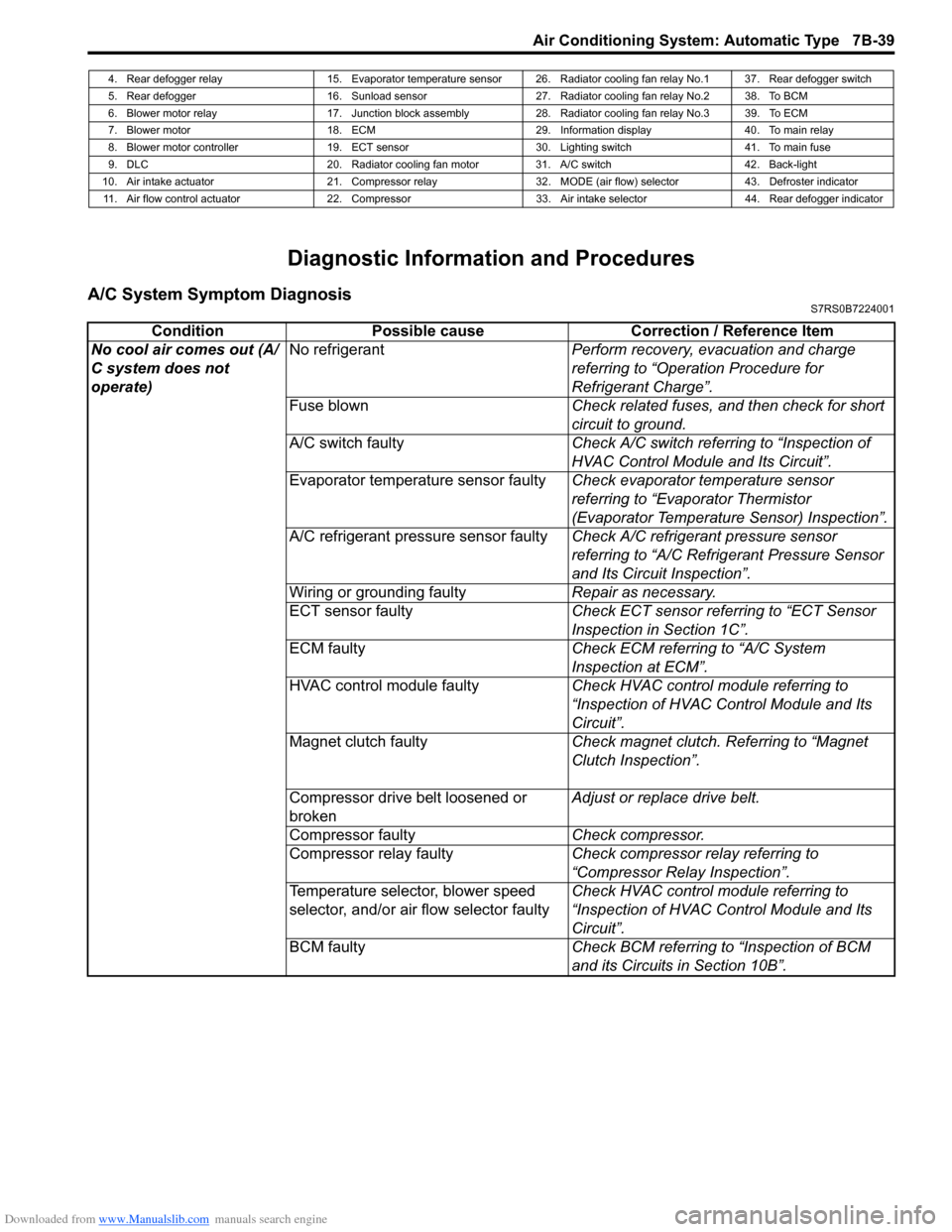
A/C System Symptom DiagnosisS7RS0B7224001
4. Rear defogger relay 15. Evaporator temperature sensor 26. Radiator cooling fan relay No.1 37. Rear defogger switch
5. Rear defogger 16. Sunload sensor 27. Radiator cooling fan relay No.2 38. To BCM
6. Blower motor relay 17. Junction block assembly 28. Radiator cooling fan relay No.3 39. To ECM
7. Blower motor 18. ECM 29. Information display 40. To main relay
8. Blower motor controller 19. ECT sensor 30. Lighting switch 41. To main fuse
9. DLC 20. Radiator cooling fan motor 31. A/C switch 42. Back-light
10. Air intake actuator 21. Compressor relay 32. MODE (air flow) selector 43. Defroster indicator 11. Air flow control actuator 22. Compressor 33. Air intake selector 44. Rear defogger indicator
Condition Possible cause Correction / Reference Item
No cool air comes out (A/
C system does not
operate) No refrigerant
Perform recovery, evacuation and charge
referring to “Operation Procedure for
Refrigerant Charge”.
Fuse blown Check related fuses, and then check for short
circuit to ground.
A/C switch faulty Check A/C switch referring to “Inspection of
HVAC Control Module and Its Circuit”.
Evaporator temperature sensor faulty Check evaporator temperature sensor
referring to “Evaporator Thermistor
(Evaporator Temperature Sensor) Inspection”.
A/C refrigerant pressure sensor faulty Check A/C refrigerant pressure sensor
referring to “A/C Refrigerant Pressure Sensor
and Its Circuit Inspection”.
Wiring or grounding faulty Repair as necessary.
ECT sensor faulty Check ECT sensor referring to “ECT Sensor
Inspection in Section 1C”.
ECM faulty Check ECM referring to “A/C System
Inspection at ECM”.
HVAC control module faulty Check HVAC control module referring to
“Inspection of HVAC Control Module and Its
Circuit”.
Magnet clutch faulty Check magnet clutch. Referring to “Magnet
Clutch Inspection”.
Compressor drive belt loosened or
broken Adjust or replace drive belt.
Compressor faulty Check compressor.
Compressor relay faulty Check compressor relay referring to
“Compressor Relay Inspection”.
Temperature selector, blower speed
selector, and/or air flow selector faulty Check HVAC control module referring to
“Inspection of HVAC Control Module and Its
Circuit”.
BCM faulty Check BCM referring to “Inspection of BCM
and its Circuits in Section 10B”.
Page 988 of 1496
Downloaded from www.Manualslib.com manuals search engine 7B-40 Air Conditioning System: Automatic Type
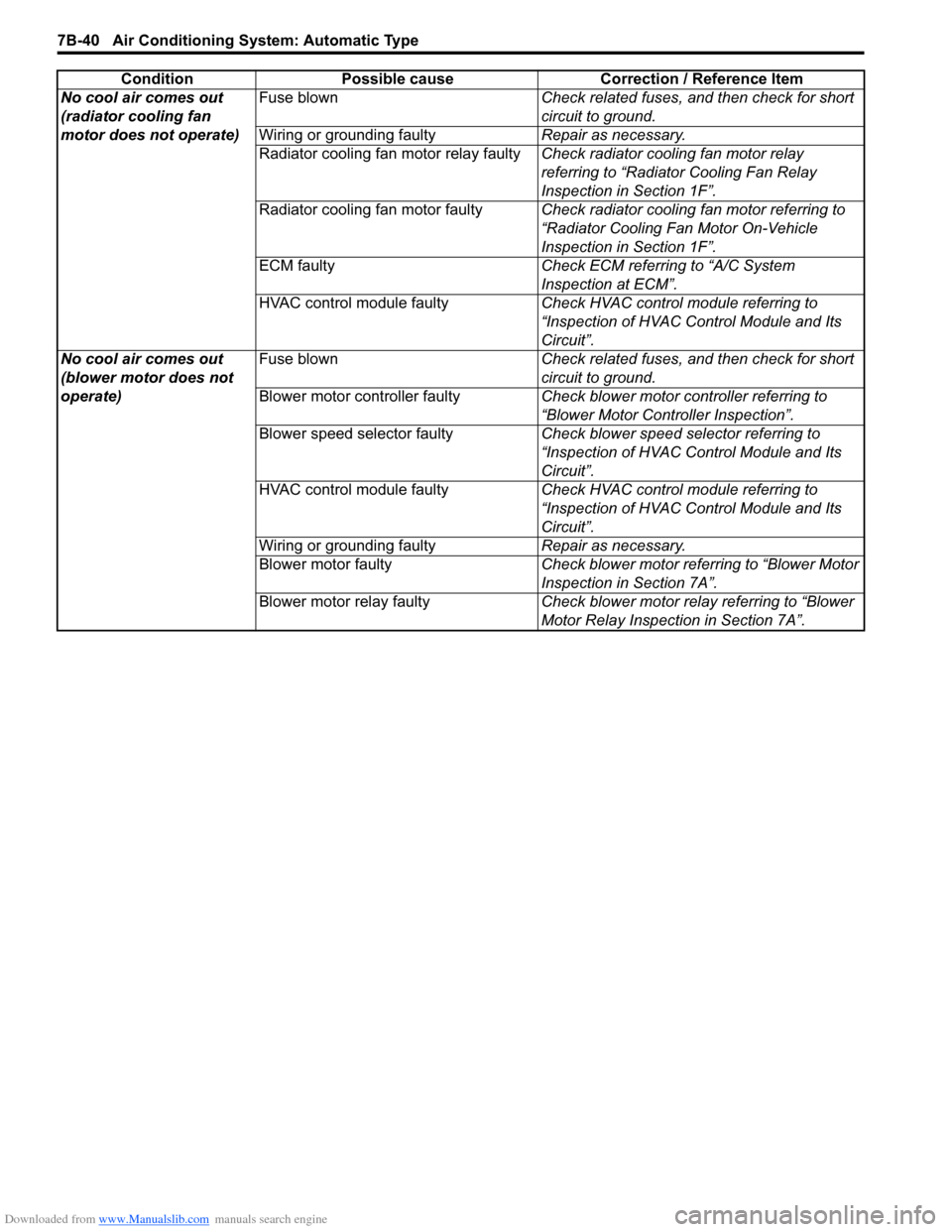
No cool air comes out
(radiator cooling fan
motor does not operate)Fuse blown
Check related fuses, and then check for short
circuit to ground.
Wiring or grounding faulty Repair as necessary.
Radiator cooling fan motor relay faulty Check radiator cooling fan motor relay
referring to “Radiator Cooling Fan Relay
Inspection in Section 1F”.
Radiator cooling fan motor faulty Check radiator cooling fan motor referring to
“Radiator Cooling Fan Motor On-Vehicle
Inspection in Section 1F”.
ECM faulty Check ECM referring to “A/C System
Inspection at ECM”.
HVAC control module faulty Check HVAC control module referring to
“Inspection of HVAC Control Module and Its
Circuit”.
No cool air comes out
(blower motor does not
operate) Fuse blown
Check related fuses, and then check for short
circuit to ground.
Blower motor controller faulty Check blower motor controller referring to
“Blower Motor Controller Inspection”.
Blower speed selector faulty Check blower speed selector referring to
“Inspection of HVAC Control Module and Its
Circuit”.
HVAC control module faulty Check HVAC control module referring to
“Inspection of HVAC Control Module and Its
Circuit”.
Wiring or grounding faulty Repair as necessary.
Blower motor faulty Check blower motor referring to “Blower Motor
Inspection in Section 7A”.
Blower motor relay faulty Check blower motor relay referring to “Blower
Motor Relay Inspection in Section 7A”.
Condition Possible cause Correction / Reference Item
Page 1013 of 1496
Downloaded from www.Manualslib.com manuals search engine Air Conditioning System: Automatic Type 7B-65
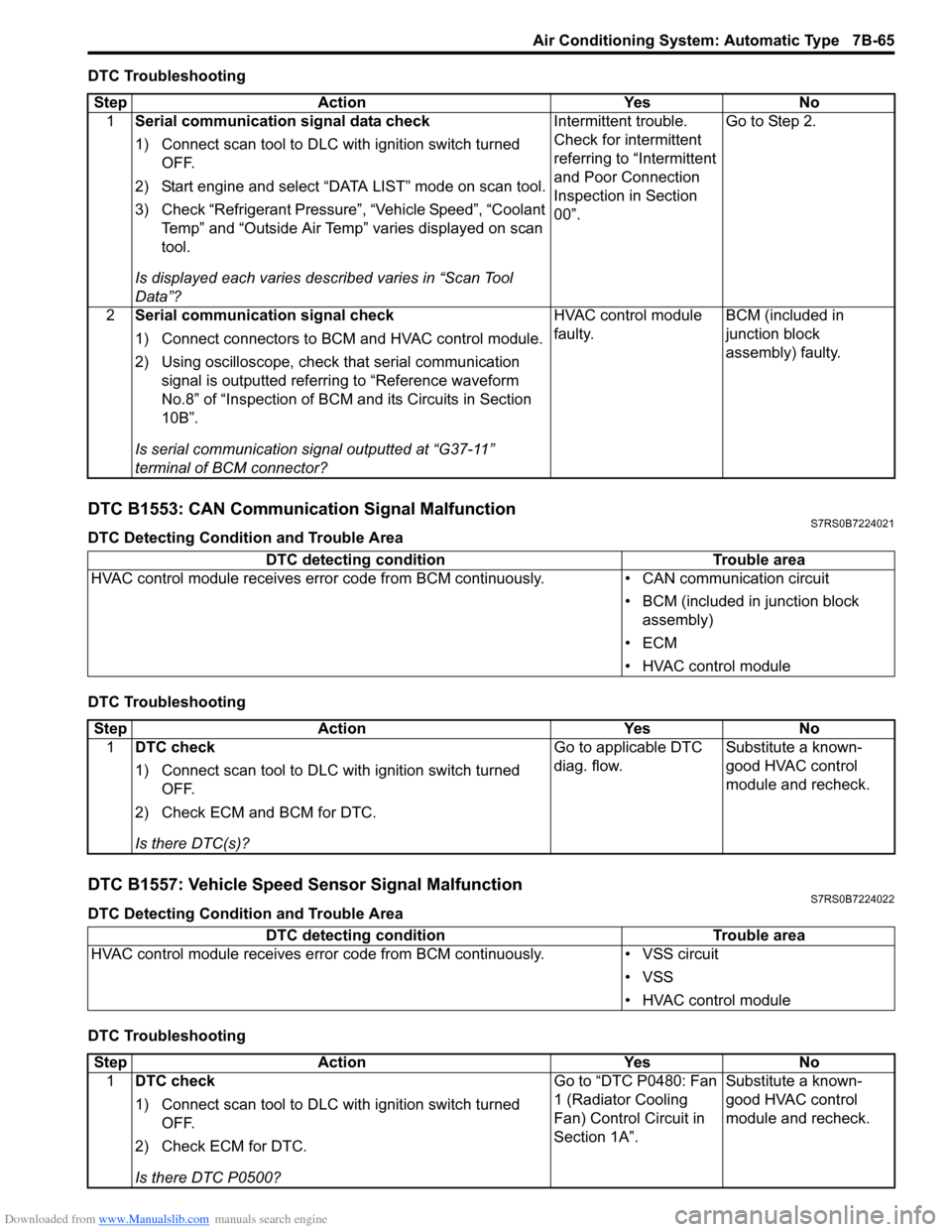
DTC Troubleshooting
DTC B1553: CAN Communication Signal MalfunctionS7RS0B7224021
DTC Detecting Condition and Trouble Area
DTC Troubleshooting
DTC B1557: Vehicle Speed Sensor Signal MalfunctionS7RS0B7224022
DTC Detecting Condition and Trouble Area
DTC TroubleshootingStep Action Yes No
1 Serial communication signal data check
1) Connect scan tool to DLC with ignition switch turned
OFF.
2) Start engine and select “DATA LIST” mode on scan tool.
3) Check “Refrigerant Pressure”, “Vehicle Speed”, “Coolant Temp” and “Outside Air Temp” varies displayed on scan
tool.
Is displayed each va ries described varies in “Scan Tool
Data”? Intermittent trouble.
Check for intermittent
referring to “Intermittent
and Poor Connection
Inspection in Section
00”.
Go to Step 2.
2 Serial communication signal check
1) Connect connectors to BCM and HVAC control module.
2) Using oscilloscope, check that serial communication
signal is outputted referring to “Reference waveform
No.8” of “Inspection of BCM and its Circuits in Section
10B”.
Is serial communication signal outputted at “G37-11”
terminal of BCM connector? HVAC control module
faulty.
BCM (included in
junction block
assembly) faulty.
DTC detecting condition
Trouble area
HVAC control module receives error code fr om BCM continuously.• CAN communication circuit
• BCM (included in junction block assembly)
•ECM
• HVAC control module
Step Action YesNo
1 DTC check
1) Connect scan tool to DLC with ignition switch turned
OFF.
2) Check ECM and BCM for DTC.
Is there DTC(s)? Go to applicable DTC
diag. flow.
Substitute a known-
good HVAC control
module and recheck.
DTC detecting condition
Trouble area
HVAC control module receives error code from BCM continuously. • VSS circuit
• VSS
• HVAC control module
Step Action YesNo
1 DTC check
1) Connect scan tool to DLC with ignition switch turned
OFF.
2) Check ECM for DTC.
Is there DTC P0500? Go to “DTC P0480: Fan
1 (Radiator Cooling
Fan) Control Circuit in
Section 1A”.
Substitute a known-
good HVAC control
module and recheck.
Page 1019 of 1496
Downloaded from www.Manualslib.com manuals search engine Air Conditioning System: Automatic Type 7B-71
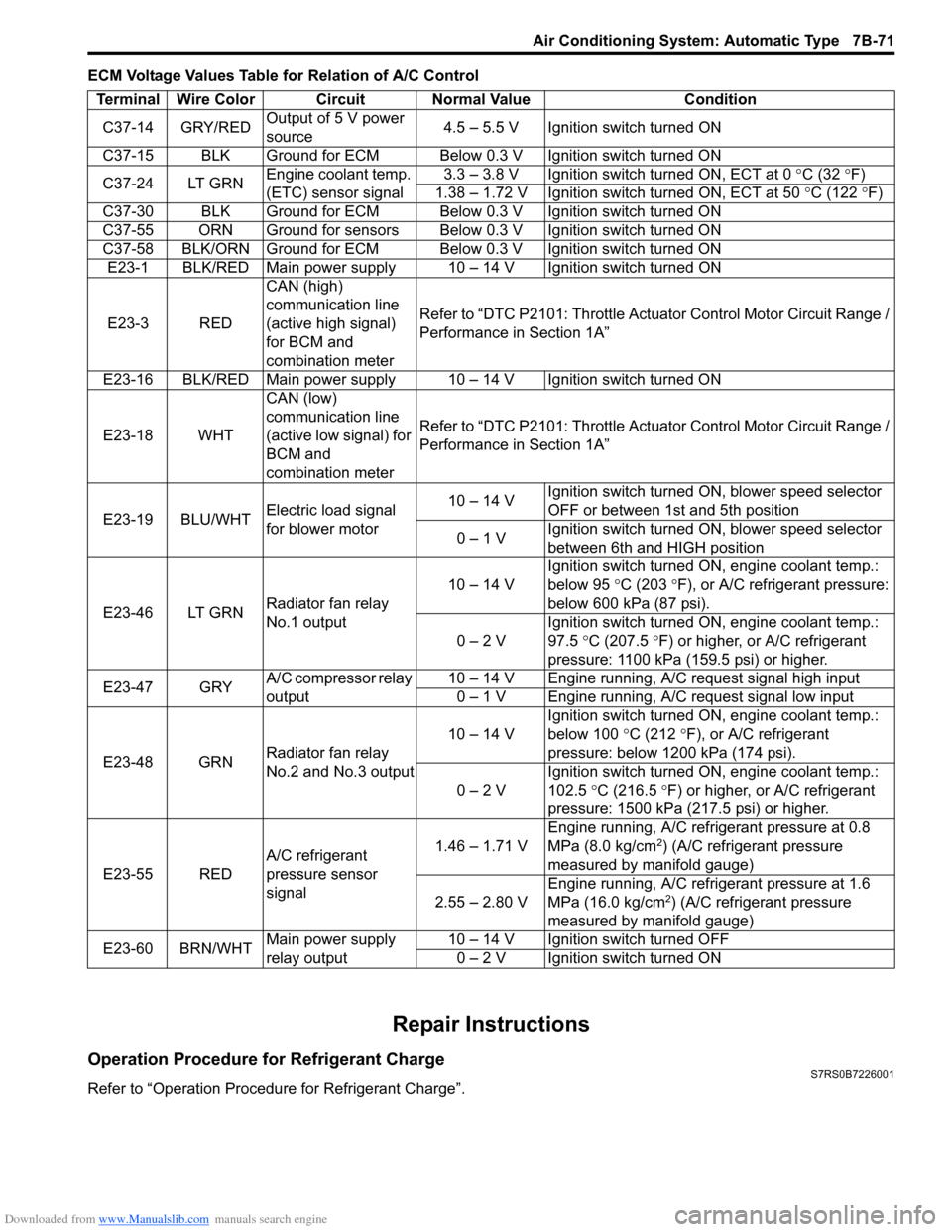
ECM Voltage Values Table for Relation of A/C Control
Repair Instructions
Operation Procedure for Refrigerant ChargeS7RS0B7226001
Refer to “Operation Procedure for Refrigerant Charge”.Terminal Wire Color Circuit Normal Value Condition
C37-14 GRY/RED Output of 5 V power
source 4.5 – 5.5 V Ignition switch turned ON
C37-15 BLK Ground for ECM Below 0.3 V Ignition switch turned ON
C37-24 LT GRN Engine coolant temp.
(ETC) sensor signal 3.3 – 3.8 V Ignition switch turned ON, ECT at 0
°C (32 ° F)
1.38 – 1.72 V Ignition switch turned ON, ECT at 50 °C (122 °F)
C37-30 BLK Ground for ECM Below 0.3 V Ignition switch turned ON
C37-55 ORN Ground for sensors Below 0.3 V Ignition switch turned ON
C37-58 BLK/ORN Ground for ECM Below 0.3 V Ignition switch turned ON E23-1 BLK/RED Main power supply 10 – 14 V Ignition switch turned ON
E23-3 RED CAN (high)
communication line
(active high signal)
for BCM and
combination meterRefer to “DTC P2101: Throttle Actu
ator Control Motor Circuit Range /
Performance in Section 1A”
E23-16 BLK/RED Main power supply 10 – 14 V Ignition switch turned ON
E23-18 WHT CAN (low)
communication line
(active low signal) for
BCM and
combination meterRefer to “DTC P2101: Throttle Actu
ator Control Motor Circuit Range /
Performance in Section 1A”
E23-19 BLU/WHT Electric load signal
for blower motor 10 – 14 V
Ignition switch turned ON, blower speed selector
OFF or between 1st and 5th position
0 – 1 V Ignition switch turned ON, blower speed selector
between 6th and HIGH position
E23-46 LT GRN Radiator fan relay
No.1 output 10 – 14 V
Ignition switch turned ON, engine coolant temp.:
below 95
°C (203 ° F), or A/C refrigerant pressure:
below 600 kPa (87 psi).
0 – 2 V Ignition switch turned ON, engine coolant temp.:
97.5
°C (207.5 °F) or higher, or A/C refrigerant
pressure: 1100 kPa (159.5 psi) or higher.
E23-47 GRY A/C compressor relay
output 10 – 14 V Engine running, A/C request signal high input
0 – 1 V Engine running, A/C request signal low input
E23-48 GRN Radiator fan relay
No.2 and No.3 output 10 – 14 V
Ignition switch turned ON, engine coolant temp.:
below 100
°C (212 °F), or A/C refrigerant
pressure: below 1200 kPa (174 psi).
0 – 2 V Ignition switch turned ON, engine coolant temp.:
102.5
°C (216.5 ° F) or higher, or A/C refrigerant
pressure: 1500 kPa (217.5 psi) or higher.
E23-55 RED A/C refrigerant
pressure sensor
signal 1.46 – 1.71 V
Engine running, A/C refrigerant pressure at 0.8
MPa (8.0 kg/cm
2) (A/C refrigerant pressure
measured by manifold gauge)
2.55 – 2.80 V Engine running, A/C refrigerant pressure at 1.6
MPa (16.0 kg/cm
2) (A/C refrigerant pressure
measured by manifold gauge)
E23-60 BRN/WHT Main power supply
relay output 10 – 14 V Ignition switch turned OFF
0 – 2 V Ignition switch turned ON
Page 1174 of 1496
Downloaded from www.Manualslib.com manuals search engine 9A-3 Wiring Systems:
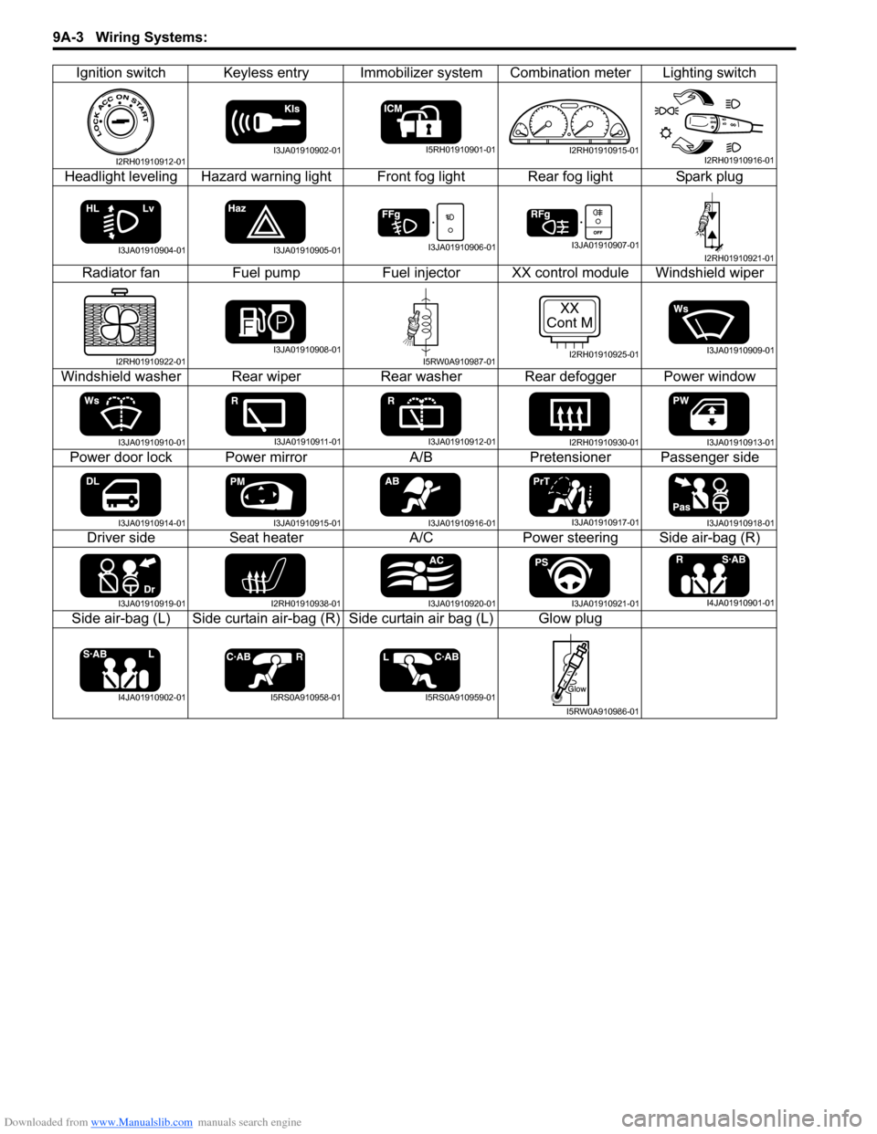
Ignition switch Keyless entry Immobilizer system Combination meter Lighting switch
Headlight leveling Hazard warning light Front fog light Rear fog light Spark plug Radiator fan Fuel pumpFuel injectorXX control module Windshield wiper
Windshield washer Rear wiper Rear washer Rear defogger Power window
Power door lock Power mirror A/BPretensioner Passenger side
Driver side Seat heater A/CPower steering Side air-bag (R)
Side air-bag (L) Side curtain air-bag (R) Side curtain air bag (L) Glow plug
I2RH01910912-01I3JA01910902-01I5RH01910901-01I2RH01910915-01I2RH01910916-01
I3JA01910904-01I3JA01910905-01I3JA01910906-01I3JA01910907-01I2RH01910921-01
I2RH01910922-01I3JA01910908-01I5RW0A910987-01
XX
Cont M
I2RH01910925-01I3JA01910909-01
I3JA01910910-01I3JA01910911-01I3JA01910912-01I2RH01910930-01I3JA01910913-01
I3JA01910914-01I3JA01910915-01I3JA01910916-01I3JA01910917-01I3JA01910918-01
I3JA01910919-01I2RH01910938-01I3JA01910920-01I3JA01910921-01I4JA01910901-01
I4JA01910902-01I5RS0A910958-01I5RS0A910959-01
I5RW0A910986-01
Page 1185 of 1496

Downloaded from www.Manualslib.com manuals search engine Wiring Systems: 9A-14
E: Main harness (RHD)
E: Main harness
56
E06E12
E03or
E85
E07
E09
E08
E13
E10
E11E05 E04
E01 E02
E19
7
22
E34E31
E32
E57
E24
(TO C36)
E33
E36
E35
E30
E29
E28
E20
E21
E22
E27
E26
E23
E25E17E56
E18
E14 E15
E55
E
I7RS0B910902-02
No./Color
Connective position No./ColorConnective position
E01/GRY Windshield wiper motor E22/N Front position light (L)
E02/GRY Brake fluid level switch E23/GRY ECM
E03/BLK ABS control module E24/N Engine Harness (To C36)
E04/BLK A/C pressure sensor E25/BLK Wheel speed sensor (FL)
E05/BLK Wheel speed sensor (FR) E26/N Main fuse box
E06/N Side turn signal light (R) E27/BLK Main fuse box
E07/N Front position light (R) E28/BLK Radiator fan relay #1
E08/BLK Head light (R) E29/BLK Radiator fan relay #2
E09/GRY Front turn signal light (R) E30/BLK Radiator fan relay #3
E10/GRN Rear washer motor E31/BLK Starting motor relay
E11/BLU Windshield washer motor E32/BLK Main relay
E12/BLK (IF EQPD) Front fog light (R)
E33/BLK A/T relay
E13/YEL Forward sensor E34/BLK (IF
EQPD) Front fog light relay
E14/BLK Outside air temperature sensor E35/BLK Fuel pump relay
E15/BLK Horn E36/BLK A/C compressor relay
E17/BLK Radiator fan motor E55/- Weld splice
E18/BLK (IF EQPD) Front fog light (L) E56/BLK
(M16A
engine) Throttle actuator control relay
E19/N Side turn signal light (L) E57/BLK Diagnosis connector #1
E20/GRY Front turn signal light (L) E85/BLK (IF
EQPD) ESP
® control module
E21/BLK Headlight (R)
Page 1186 of 1496
Downloaded from www.Manualslib.com manuals search engine 9A-15 Wiring Systems:
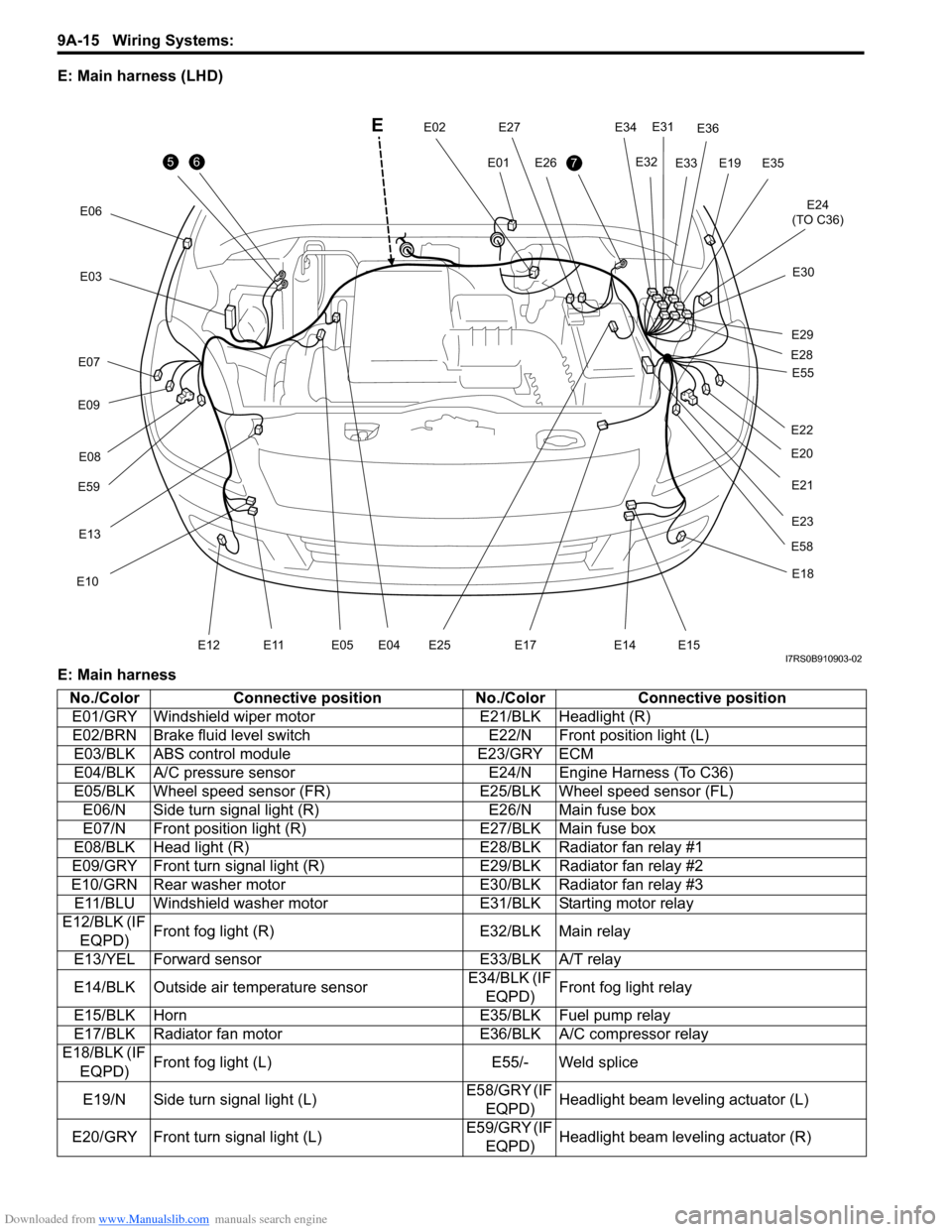
E: Main harness (LHD)
E: Main harness
56
E06E12
E
E03
E07
E09
E59E08
E13
E10
E11E05 E04
E01
E02E197
E34
E31
E32
E24
(TO C36)
E33
E36
E35
E30
E29
E28
E20
E21
E22
E58
E27
E26
E23
E25E17
E18
E14 E15
E55
I7RS0B910903-02
No./Color
Connective position No./ColorConnective position
E01/GRY Windshield wiper motor E21/BLK Headlight (R)
E02/BRN Brake fluid level switch E22/N Front position light (L)
E03/BLK ABS control module E23/GRY ECM
E04/BLK A/C pressure sensor E24/N Engine Harness (To C36)
E05/BLK Wheel speed sensor (FR) E25/BLK Wheel speed sensor (FL)
E06/N Side turn signal light (R) E26/N Main fuse box
E07/N Front position light (R) E27/BLK Main fuse box
E08/BLK Head light (R) E28/BLK Radiator fan relay #1
E09/GRY Front turn signal light (R) E29/BLK Radiator fan relay #2
E10/GRN Rear washer motor E30/BLK Radiator fan relay #3
E11/BLU Windshield washer motor E31/BLK Starting motor relay
E12/BLK (IF EQPD) Front fog light (R)
E32/BLK Main relay
E13/YEL Forward sensor E33/BLK A/T relay
E14/BLK Outside air temperature sensor E34/BLK (IF
EQPD) Front fog light relay
E15/BLK Horn E35/BLK Fuel pump relay
E17/BLK Radiator fan motor E36/BLK A/C compressor relay
E18/BLK (IF
EQPD) Front fog light (L)
E55/- Weld splice
E19/N Side turn signal light (L) E58/GRY (IF
EQPD) Headlight beam leveling actuator (L)
E20/GRY Front turn signal light (L) E59/GRY (IF
EQPD) Headlight beam leveling actuator (R)