2005 SUZUKI SWIFT Body control modul
[x] Cancel search: Body control modulPage 913 of 1496
Downloaded from www.Manualslib.com manuals search engine Power Assisted Steering System: 6C-31
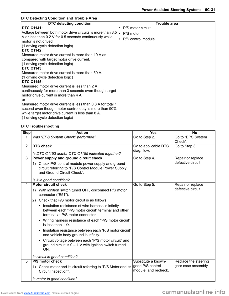
DTC Detecting Condition and Trouble Area
DTC TroubleshootingDTC detecting condition Trouble area
DTC C1141:
Voltage between both motor drive circuits is more than 8.5
V or less than 0.2 V for 0.5 seconds continuously while
motor is not drived
(1 driving cycle detection logic)
DTC C1142:
Measured motor drive current is more than 10 A as
compared with target motor drive current.
(1 driving cycle detection logic)
DTC C1143:
Measured motor drive current is more than 50 A.
(1 driving cycle detection logic)
DTC C1145:
Measured motor drive current is less than 2 A
continuously for more than 3 seconds even though target
motor drive current is more than 4 A.
or
Measured motor drive current is less than 0.8 A for total 1
second even though motor cont rol duty is more than 90%
while target motor drive current is less than 8 A.
(1 driving cycle detection logic) • P/S motor circuit
• P/S motor
• P/S control module
Step
Action YesNo
1 Was “EPS System Check” performed? Go to Step 2.Go to “EPS System
Check”.
2 DTC check
Is DTC C1153 and/or DTC C1155 indicated together? Go to applicable DTC
diag. flow.
Go to Step 3.
3 Power supply and ground circuit check
1) Check P/S control module power supply and ground
circuit referring to “P/S Control Module Power Supply
and Ground Circuit Check”.
Is it in good condition? Go to Step 4.
Repair or replace
defective circuit.
4 Motor circuit check
1) With ignition switch tuned OFF, disconnect P/S motor
connector (“E51”).
2) Check that P/S motor circuit is as follows. • Insulation resistance of wire harness is infinity between each “P/S motor circuit” terminal and other
terminal at P/S motor connector.
• Wiring harness resistance of each “P/S motor circuit”
is less than 1 Ω.
• Insulation resistance between each “P/S motor circuit” and vehicle body ground is infinity.
• Circuit voltage between each “P/S motor circuit” and ground circuit is 0 – 1 V with ignition switch turned
ON.
Is circuit in good condition? Go to Step 5.
Repair or replace
defective circuit.
5 P/S motor check
1) Check motor and its circuit referring to “P/S Motor and Its
Circuit Inspection”.
Is motor in good condition? Substitute a known-
good P/S control
module, and recheck.
Replace the steering
gear case assembly.
Page 914 of 1496
Downloaded from www.Manualslib.com manuals search engine 6C-32 Power Assisted Steering System:
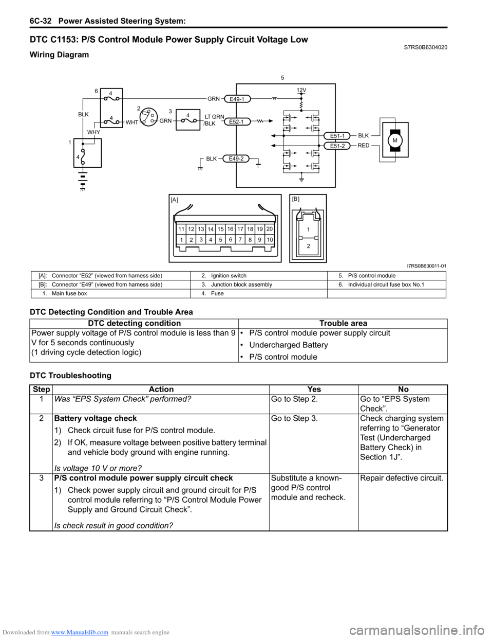
DTC C1153: P/S Control Module Power Supply Circuit Voltage LowS7RS0B6304020
Wiring Diagram
DTC Detecting Condition and Trouble Area
DTC Troubleshooting
MBLK
REDE51-1
E51-2
12V
5
[A ]
12 3
4 5 67
89
11
10
12 13
141516
17 18 19 20
[B ]
1
2
LT GRN
/BLKE52-1 E49-1
GRNGRNWHTBLK
WHY
6
3
4
4
4
4
1 2
E49-2BLK
I7RS0B630011-01
[A]: Connector “E52” (viewed from harness side)
2. Ignition switch5. P/S control module
[B]: Connector “E49” (viewed from harness side) 3. Junction block assembly 6. Individual circuit fuse box No.1
1. Main fuse box 4. Fuse
DTC detecting condition Trouble area
Power supply voltage of P/S control module is less than 9
V for 5 seconds continuously
(1 driving cycle detection logic) • P/S control module power supply circuit
• Undercharged Battery
• P/S control module
Step
Action YesNo
1 Was “EPS System Check” performed? Go to Step 2.Go to “EPS System
Check”.
2 Battery voltage check
1) Check circuit fuse for P/S control module.
2) If OK, measure voltage between positive battery terminal
and vehicle body ground with engine running.
Is voltage 10 V or more? Go to Step 3.
Check charging system
referring to “Generator
Test (Undercharged
Battery Check) in
Section 1J”.
3 P/S control module power supply circuit check
1) Check power supply circuit and ground circuit for P/S
control module referring to “P/S Control Module Power
Supply and Ground Circuit Check”.
Is check result in good condition? Substitute a known-
good P/S control
module and recheck.
Repair defective circuit.
Page 915 of 1496
Downloaded from www.Manualslib.com manuals search engine Power Assisted Steering System: 6C-33
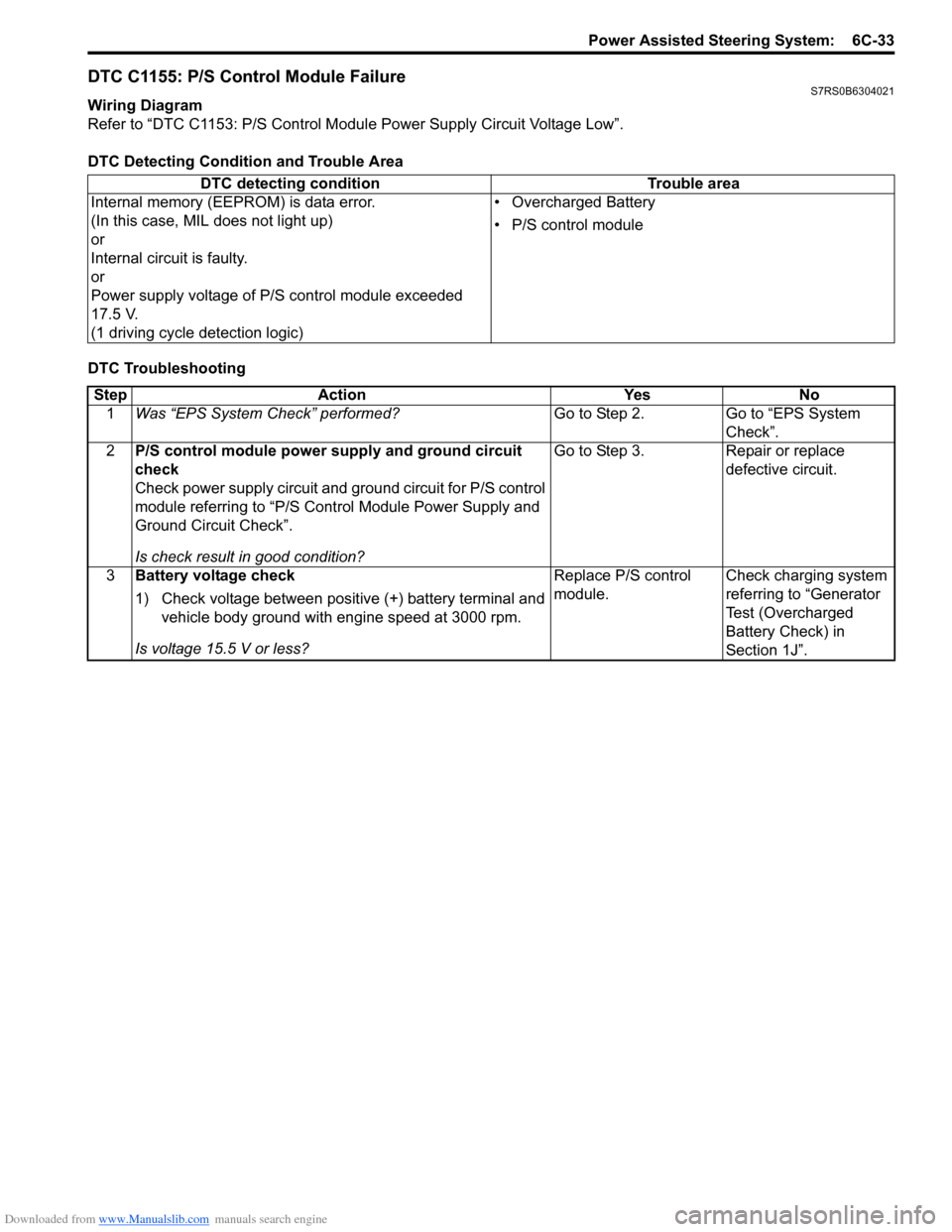
DTC C1155: P/S Control Module FailureS7RS0B6304021
Wiring Diagram
Refer to “DTC C1153: P/S Control Module Power Supply Circuit Voltage Low”.
DTC Detecting Condition and Trouble Area
DTC Troubleshooting DTC detecting condition Trouble area
Internal memory (EEPROM) is data error.
(In this case, MIL does not light up)
or
Internal circuit is faulty.
or
Power supply voltage of P/S control module exceeded
17.5 V.
(1 driving cycle detection logic) • Overcharged Battery
• P/S control module
Step
Action YesNo
1 Was “EPS System Check” performed? Go to Step 2.Go to “EPS System
Check”.
2 P/S control module power supply and ground circuit
check
Check power supply circuit and ground circuit for P/S control
module referring to “P/S Control Module Power Supply and
Ground Circuit Check”.
Is check result in good condition? Go to Step 3.
Repair or replace
defective circuit.
3 Battery voltage check
1) Check voltage between positive (+) battery terminal and
vehicle body ground with engine speed at 3000 rpm.
Is voltage 15.5 V or less? Replace P/S control
module.
Check charging system
referring to “Generator
Test (Overcharged
Battery Check) in
Section 1J”.
Page 916 of 1496
![SUZUKI SWIFT 2005 2.G Service Workshop Manual Downloaded from www.Manualslib.com manuals search engine 6C-34 Power Assisted Steering System:
P/S Control Module Power Supply and Ground Circuit CheckS7RS0B6304022
Wiring Diagram
1
[A ]
123
4 5 67
8 SUZUKI SWIFT 2005 2.G Service Workshop Manual Downloaded from www.Manualslib.com manuals search engine 6C-34 Power Assisted Steering System:
P/S Control Module Power Supply and Ground Circuit CheckS7RS0B6304022
Wiring Diagram
1
[A ]
123
4 5 67
8](/manual-img/20/7607/w960_7607-915.png)
Downloaded from www.Manualslib.com manuals search engine 6C-34 Power Assisted Steering System:
P/S Control Module Power Supply and Ground Circuit CheckS7RS0B6304022
Wiring Diagram
1
[A ]
123
4 5 67
89
11
10
12 13
141516
17 18 19 20
[B ]
7
1
2
MBLK
REDE51-1
E51-2
12V
LT GRN
/BLKE52-1 E49-1
GRNGRNWHTBLK
WHY
3
3
5
6
1 2
E49-2BLK
I7RS0B630012-01
[A]: Connector “E52” (viewed from harness side)
2. Ignition switch5. “EPS” fuse
[B]: Connector “E49” (viewed from harness side) 3. Individual circuit fuse box No.1 6. “IG1 SIG” fuse
1. Main fuse box 4. Junction block assembly7. P/S control module
StepAction YesNo
1 Circuit fuse check
1) Disconnect P/S control modu le connector with ignition
switch turned OFF.
2) Check for proper connection to P/S control module connector at “E49-1”, “E49-2” and “E52-1” terminals.
3) If OK, check “P/S” fuse and “IG1 SIG” fuse for blowing.
Are “P/S” fuse and “IG1 SIG” fuse in good condition? Go to Step 2.
Replace fuse(s) and
check for short in
circuits connected to
fuse(s).
2 Power supply circuit check
1) Measure voltage between “E49-1” terminal of P/S
control module connector and body ground.
Is voltage 10 - 14 V? Go to Step 3.
“GRN” or “BLK” wire is
open circuit.
3 Ignition signal check
1) Turn ignition switch to ON position.
2) Measure voltage between “E52-1” terminal of P/S
control module connector and body ground.
Is voltage 10 - 14 V? Go to Step 4.
“LT GRN/BLK” or “GRN”
wire is open circuit.
4 P/S control module ground circuit check
1) Turn ignition switch to OFF position.
2) Disconnect connectors from P/S control module.
3) Measure resistance between “E49-2” terminals of P/S
control module connector and body ground.
Is resistance 1
Ω or less? Go to Step 5. “BLK” wire is open or
high resistance circuit.
Page 917 of 1496
Downloaded from www.Manualslib.com manuals search engine Power Assisted Steering System: 6C-35
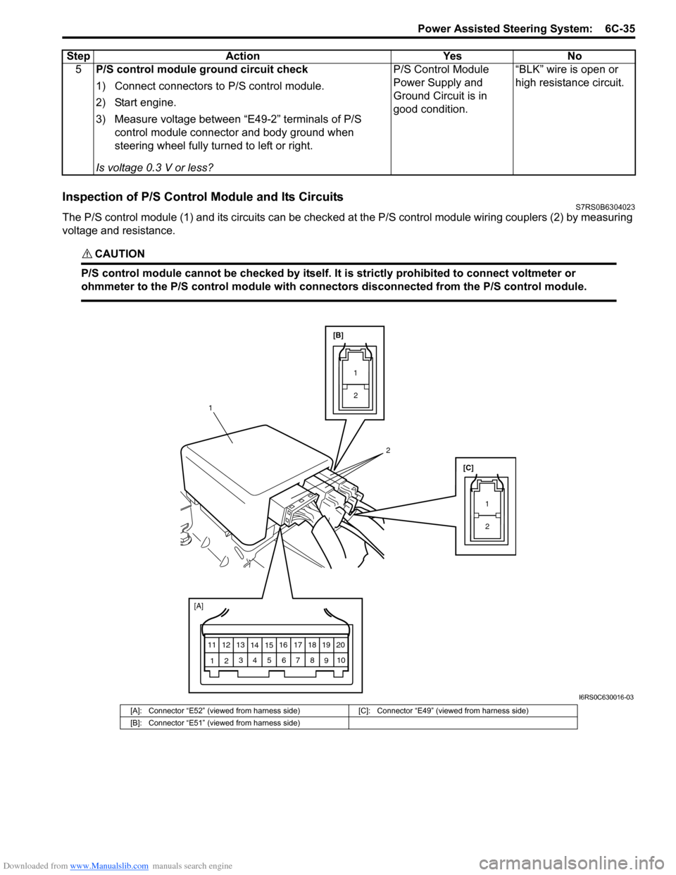
Inspection of P/S Control Module and Its CircuitsS7RS0B6304023
The P/S control module (1) and its circuits can be checked at the P/S control module wiring couplers (2) by measuring
voltage and resistance.
CAUTION!
P/S control module cannot be checked by itself. It is strictly prohibited to connect voltmeter or
ohmmeter to the P/S control module with connectors disconnected from the P/S control module.
5 P/S control module ground circuit check
1) Connect connectors to P/S control module.
2) Start engine.
3) Measure voltage between “E49-2” terminals of P/S
control module connector and body ground when
steering wheel fully turned to left or right.
Is voltage 0.3 V or less? P/S Control Module
Power Supply and
Ground Circuit is in
good condition.
“BLK” wire is open or
high resistance circuit.
Step Action Yes No
[A]
12
3
4 5 67
89
11
10
12 13
141516
17 18 19 20
[B]
[C]
12
1
1 2
2
I6RS0C630016-03
[A]: Connector “E52” (viewed from harness side) [C]: Connector “E49” (viewed from harness side)
[B]: Connector “E51” (viewed from harness side)
Page 918 of 1496
Downloaded from www.Manualslib.com manuals search engine 6C-36 Power Assisted Steering System:
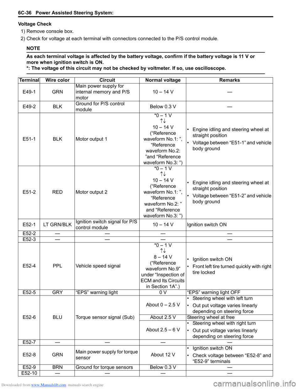
Voltage Check1) Remove console box.
2) Check for voltage at each terminal with co nnectors connected to the P/S control module.
NOTE
As each terminal voltage is affected by the battery voltage, confirm if the battery voltage is 11 V or
more when ignition switch is ON.
*: The voltage of this circuit may not be checked by voltmeter. If so, use oscilloscope.
Terminal Wire colorCircuit Normal voltage Remarks
E49-1 GRN Main power supply for
internal memory and P/S
motor 10 – 14 V
—
E49-2 BLK Ground for P/S control
module Below 0.3 V
—
E51-1 BLK Motor output 1 *0 – 1 V
↑↓
10 – 14 V
(“Reference
waveform No.1: ”, “Reference
waveform No.2:
”and “Reference
waveform No.3: ”) • Engine idling and steering wheel at
straight position
• Voltage between “E51-1” and vehicle body ground
E51-2 RED Motor output 2 *0 – 1 V
↑↓
10 – 14 V
(“Reference
waveform No.1: ”, “Reference
waveform No.2: ” and “Reference
waveform No.3: ”) • Engine idling and steering wheel at
straight position
• Voltage between “E51-2” and vehicle body ground
E52-1 LT GRN/BLK Ignition switch signal for P/S
control module 10 – 14 V Ignition switch ON
E52-2 — —— —
E52-3 — —— —
E52-4 PPL Vehicle speed signal *0 – 1 V
↑↓
8 – 14 V
(“Reference
waveform No.9”
under “Inspection of
ECM and Its Circuits in Section 1A”.) • Ignition switch ON
•Front left tire tu
rned quickly with right
tire locked
E52-5 GRY “EPS” warning light 0 V “EPS” warning light OFF
E52-6 BLU Torque sensor signal (Sub) About 0 – 2.5 V
• Steering wheel with left turn
• Out put voltage varies linearly
depending on steering force
About 2.5 V Steering wheel at free
About 2.5 – 6 V • Steering wheel with right turn
• Out put voltage varies linearly
depending on steering force
E52-7 — —— —
E52-8 GRN Main power supply for torque
sensor About 12 V• Ignition switch ON
• Check voltage between “E52-8” and
“E52-9” terminals
E52-9 BRN Ground for torque sensors Below 0.3 V —
E52-10 — —— —
Page 929 of 1496
Downloaded from www.Manualslib.com manuals search engine Power Assisted Steering System: 6C-47
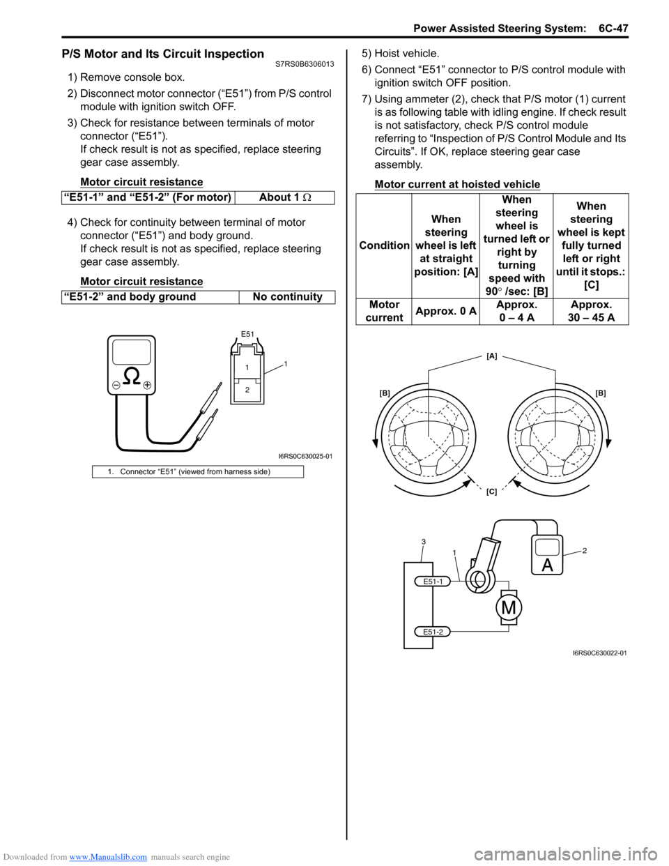
P/S Motor and Its Circuit InspectionS7RS0B6306013
1) Remove console box.
2) Disconnect motor connector (“E51”) from P/S control module with ignition switch OFF.
3) Check for resistance between terminals of motor connector (“E51”).
If check result is not as specified, replace steering
gear case assembly.
Motor circuit resistance
4) Check for continuity between terminal of motor connector (“E51”) and body ground.
If check result is not as specified, replace steering
gear case assembly.
Motor circuit resistance
5) Hoist vehicle.
6) Connect “E51” connector to P/S control module with ignition switch OFF position.
7) Using ammeter (2), check that P/S motor (1) current is as following table with id ling engine. If check result
is not satisfactory, check P/S control module
referring to “Inspection of P/S Control Module and Its
Circuits”. If OK, replace steering gear case
assembly.
Motor current at hoisted vehicle
“E51-1” and “E51-2” (For motor) About 1 Ω
“E51-2” and body ground No continuity
1. Connector “E51” (viewed from harness side)
E51
11 2
I6RS0C630025-01
Condition When
steering
wheel is left at straight
position: [A] When
steering
wheel is
turned left or right by turning
speed with
90° /sec: [B] When
steering
wheel is kept fully turned left or right
until it stops.: [C]
Motor
current Approx. 0 A Approx.
0 – 4 A Approx.
30 – 45 A
1
32
E51-1
E51-2
[C] [A]
[B] [B]
I6RS0C630022-01
Page 982 of 1496

Downloaded from www.Manualslib.com manuals search engine 7B-34 Air Conditioning System: Automatic Type
Automatic Type
Precautions
A/C System CautionS7RS0B7220001
Refer to “A/C System Caution”.
Precautions in Diagnosing TroubleS7RS0B7220002
• Do not disconnect couplers from HVAC control module, battery cable from battery, HVAC control module ground
wire harness from body or main fuse before confirming diagnostic information (diagnostic trouble code) stored in
HVAC control module memory.
• Diagnostic information (diagnostic trouble code) stored in HVAC control module can be checked by display of HVAC
control module. Also, it can be checked by using SU ZUKI scan tool. Before checking diagnostic information
(diagnostic trouble code), read this manual and operator's manual for SUZUKI scan tool to know how to read
diagnostic information (diagnostic trouble code).
• When trouble is diagnosed using diagnostic information (diagnostic trouble code) on display of HVAC control
module, keep in your mind that each diagnostic inform ation (diagnostic trouble code) has priority, and only
diagnostic information (diagnostic troub le code) which has the highest priority is indicated. Therefore, after
troubleshooting the malfunction, make sure if there exists any other diagnostic information (diagnostic trouble
code).
• Be sure to read “Precautions for Electrical Circuit Service in Section 00” before inspection.
Precautions on Servicing A/C SystemS7RS0B7220003
Refer to “Precautions on Servicing A/C System”.
General Description
Auto A/C System DescriptionS7RS0B7221001
The automatic type air conditioning system (auto A/C) is pr ovided with the function to automatically control the inside
air temperature, fan speed, air flow outl et direction and air intake position by HVAC control module in addition to
functions of the manual type air conditioning system (manua l A/C). Once the inside air temperature is set using the
temperature selector, HVAC control module automatically controls the inside air temperature at the constant level at all
times based on the inside air temperature, outside ai r temperature, amount of sunlight and engine coolant
temperature detected respectively by the inside air te mperature sensor, outside air temperature sensor, sunload
sensor and ECT sensor. At this time, “FULL AUTO A/ C” appears on the display of HVAC control module.
With the air intake selector pushed in the above state, it is possible to select any position of the air intake actuator.
Then, “FULL AUTO A/C” on the display changes to “AUTO A/C”.