2005 SUZUKI SWIFT gauge
[x] Cancel search: gaugePage 766 of 1496
Downloaded from www.Manualslib.com manuals search engine 5A-122 Automatic Transmission/Transaxle:
Oil Pump Assembly Disassembly and
Reassembly
S7RS0B5106035
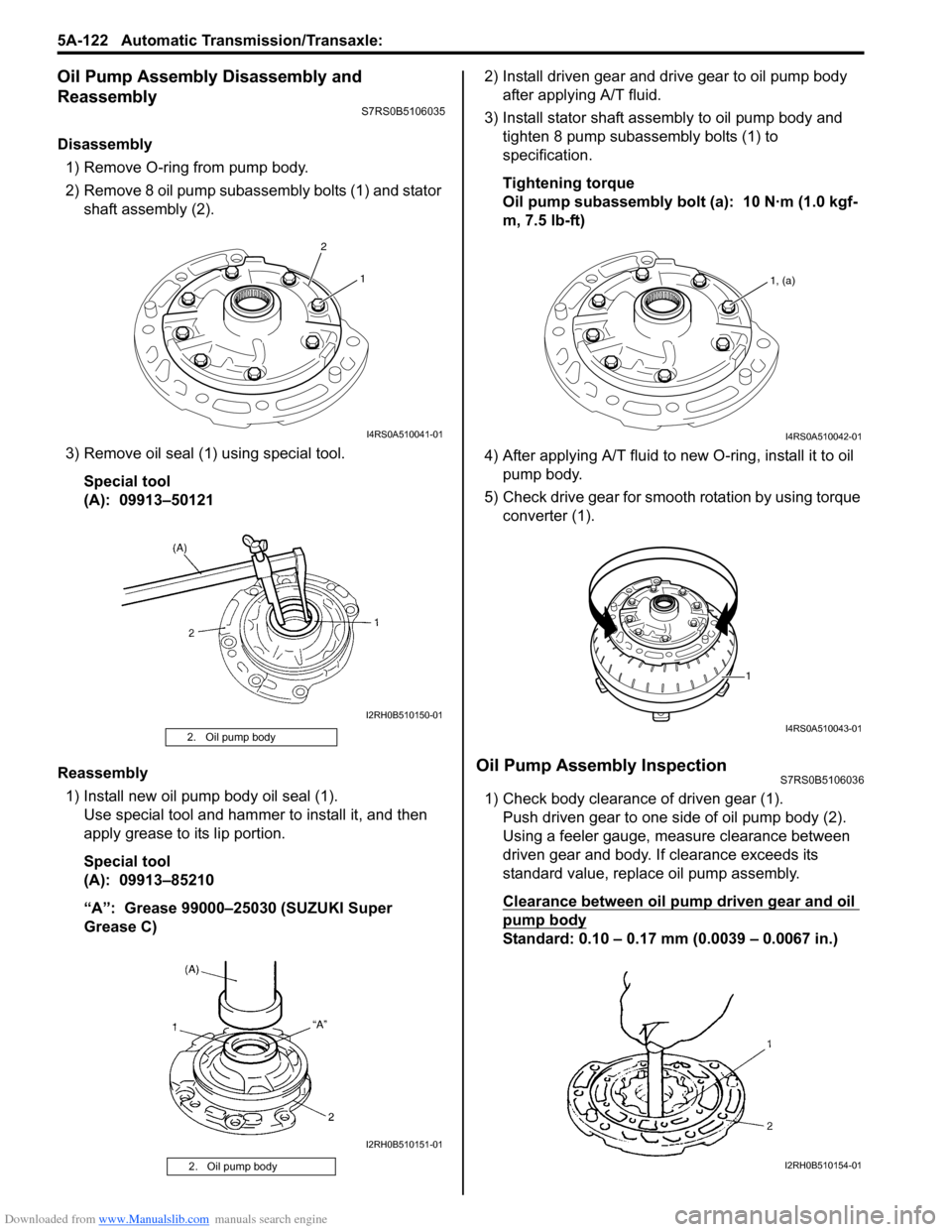
Disassembly1) Remove O-ring from pump body.
2) Remove 8 oil pump subassembly bolts (1) and stator shaft assembly (2).
3) Remove oil seal (1) using special tool. Special tool
(A): 09913–50121
Reassembly 1) Install new oil pump body oil seal (1). Use special tool and hammer to install it, and then
apply grease to its lip portion.
Special tool
(A): 09913–85210
“A”: Grease 99000–25030 (SUZUKI Super
Grease C) 2) Install driven gear and drive gear to oil pump body
after applying A/T fluid.
3) Install stator shaft assembly to oil pump body and tighten 8 pump subassembly bolts (1) to
specification.
Tightening torque
Oil pump subassembly bolt (a): 10 N·m (1.0 kgf-
m, 7.5 lb-ft)
4) After applying A/T fluid to new O-ring, install it to oil pump body.
5) Check drive gear for smooth rotation by using torque converter (1).
Oil Pump Assembly InspectionS7RS0B5106036
1) Check body clearance of driven gear (1).Push driven gear to one side of oil pump body (2).
Using a feeler gauge, m easure clearance between
driven gear and body. If clearance exceeds its
standard value, replace oil pump assembly.
Clearance between oil pump driven gear and oil
pump body
Standard: 0.10 – 0.17 mm (0.0039 – 0.0067 in.)
2. Oil pump body
2. Oil pump body
2 1
I4RS0A510041-01
I2RH0B510150-01
I2RH0B510151-01
1, (a)
I4RS0A510042-01
1
I4RS0A510043-01
I2RH0B510154-01
Page 767 of 1496

Downloaded from www.Manualslib.com manuals search engine Automatic Transmission/Transaxle: 5A-123
2) Check tip clearance of both drive and driven gears.Using a feeler gauge, m easure clearance between
drive and driven gear tips. If clearance exceeds its
standard value, replace oil pump assembly.
Tip clearance between oil pump drive gear and
oil pump driven gear
Standard: 0.07 – 0.15 mm (0.0028 – 0.0059 in.)
3) Check side clearance of both gears. Using a straightedge (1) and a feeler gauge (2),
measure side clearance between gears and pump
body.
If clearance exceeds its standard value, replace oil
pump assembly.
Side clearance between gears and oil pump body
Standard: 0.02 – 0.05 mm (0.0008 – 0.0019 in.)
4) Using special tool, measure stator shaft bush (1) bore.
If measured stator shaft bush bore is out of
specifications, replace oil pump assembly with new
one.
Special tool
(A): 09900–20605
Stator shaft bush bore
Standard: 18.424 – 18.450 mm (0.7254 – 0.7264
in.) 5) Install direct clutch asse
mbly (1) to stator shaft
assembly (2), then ensure that direct clutch
assembly turns smoothly.
If unsmooth rotation or noise are found in oil pump
assembly, replace oil pump assembly with new one.
This check should also be done to input shaft
assembly and replace input shaft assembly if
necessary.
6) Using special tool, measure oil pump body bush bore.
If measured oil pump body bush (1) bore is out of
specifications, replace o il pump assembly with new
one. Torque converter also needs to be checked.
Replace torque converter, if necessary.
Special tool
(A): 09900–20605
Oil pump body bush bore
Standard: 38.113 – 38.138 mm (1.5005 – 1.5015
in.)
I2RH0B510155-01
I2RH0B510156-01
I2RH0B510157-01
I2RH0B510158-01
I2RH0B510159-01
Page 805 of 1496
Downloaded from www.Manualslib.com manuals search engine Automatic Transmission/Transaxle: 5A-161
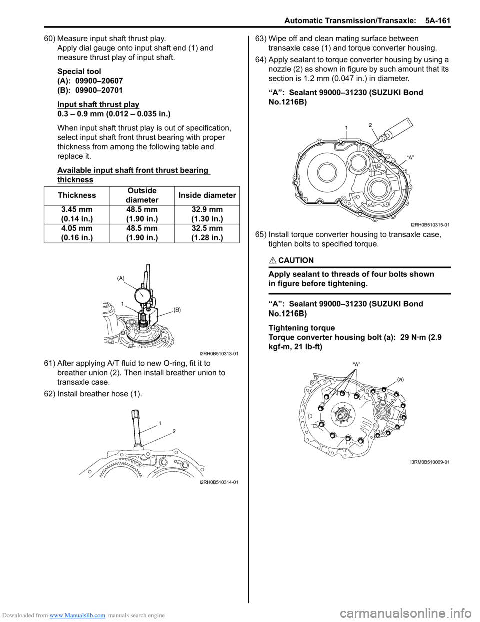
60) Measure input shaft thrust play.Apply dial gauge onto input shaft end (1) and
measure thrust play of input shaft.
Special tool
(A): 09900–20607
(B): 09900–20701
Input shaft thrust play
0.3 – 0.9 mm (0.012 – 0.035 in.)
When input shaft thrust play is out of specification,
select input shaft front th rust bearing with proper
thickness from among the following table and
replace it.
Available input shaft front thrust bearing
thickness
61) After applying A/T fluid to new O-ring, fit it to breather union (2). Then install breather union to
transaxle case.
62) Install breather hose (1). 63) Wipe off and clean mating surface between
transaxle case (1) and torque converter housing.
64) Apply sealant to torque converter housing by using a nozzle (2) as shown in figure by such amount that its
section is 1.2 mm (0.047 in.) in diameter.
“A”: Sealant 99000–31230 (SUZUKI Bond
No.1216B)
65) Install torque converter housing to transaxle case, tighten bolts to specified torque.
CAUTION!
Apply sealant to threads of four bolts shown
in figure before tightening.
“A”: Sealant 99000–31230 (SUZUKI Bond
No.1216B)
Tightening torque
Torque converter housing bolt (a): 29 N·m (2.9
kgf-m, 21 lb-ft)
Thickness
Outside
diameter Inside diameter
3.45 mm
(0.14 in.) 48.5 mm
(1.90 in.) 32.9 mm
(1.30 in.)
4.05 mm
(0.16 in.) 48.5 mm
(1.90 in.) 32.5 mm
(1.28 in.)
I2RH0B510313-01
I2RH0B510314-01
1 2
“A”
I2RH0B510315-01
I3RM0B510069-01
Page 812 of 1496
Downloaded from www.Manualslib.com manuals search engine 5A-168 Automatic Transmission/Transaxle:
Special Tools and Equipment
Recommended Service MaterialS7RS0B5108001
NOTE
Required service material is also described in the following.
“Select Cable Components”
“Automatic Transaxle Unit Components”
“Automatic Transaxle Assembly Components”
“Oil Pump Assembly Components”
“Direct Clutch Assembly Components”
“Forward and Reverse Clutch Assembly Components”
“2nd Brake Piston Assembly Components”
“Transaxle Rear Cover (O/D and 2nd Coast Brake Piston) Assembly Components”
“Countershaft Assembly Components”
“Valve Body Assembly Components”
“Differential Assembly Components”
Special ToolS7RS0B5108002
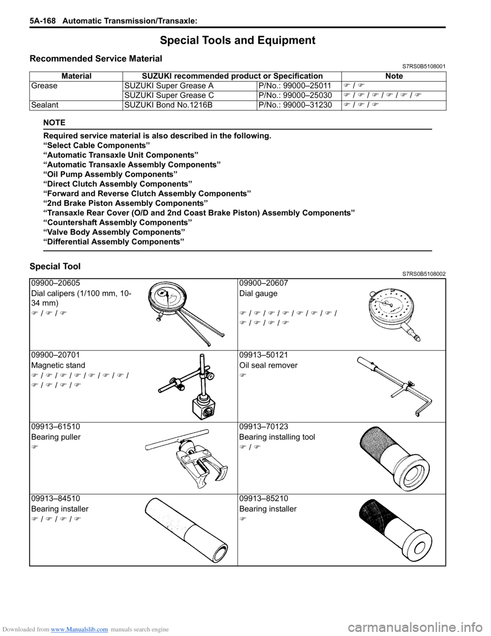
Material SUZUKI recommended product or Specification Note
Grease SUZUKI Super Grease A P/No.: 99000–25011�) / �)
SUZUKI Super Grease C P/No.: 99000–25030�) / �) / �) / �) / �) / �)
Sealant SUZUKI Bond No.1216B P/No.: 99000–31230�) / �) / �)
09900–20605 09900–20607
Dial calipers (1/100 mm, 10-
34 mm) Dial gauge
�) / �) / �)�) / �) / �) / �) / �) / �) / �) /
�) / �) / �) / �)
09900–20701 09913–50121
Magnetic stand Oil seal remover
�) / �) / �) / �) / �) / �) / �) /
�) / �) / �) / �) �)
09913–61510 09913–70123
Bearing puller Bearing installing tool
�)�) / �)
09913–84510 09913–85210
Bearing installer Bearing installer
�) / �) / �) / �)�)
Page 813 of 1496
Downloaded from www.Manualslib.com manuals search engine Automatic Transmission/Transaxle: 5A-169
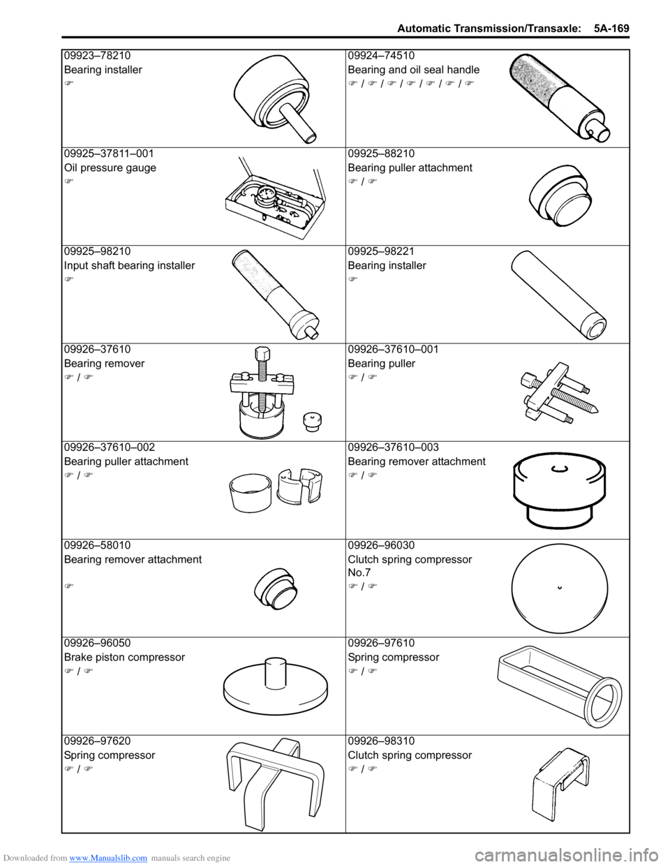
09923–7821009924–74510
Bearing installer Bearing and oil seal handle
�)�) / �) / �) / �) / �) / �) / �)
09925–37811–001 09925–88210
Oil pressure gauge Bearing puller attachment
�)�) / �)
09925–98210 09925–98221
Input shaft bearing inst aller Bearing installer
�)�)
09926–37610 09926–37610–001
Bearing remover Bearing puller
�) / �)�) / �)
09926–37610–002 09926–37610–003
Bearing puller attachment Bearing remover attachment
�) / �)�) / �)
09926–58010 09926–96030
Bearing remover attachment Clutch spring compressor
No.7
�)�) / �)
09926–96050 09926–97610
Brake piston compressor Spring compressor
�) / �)�) / �)
09926–97620 09926–98310
Spring compressor Clutch spring compressor
�) / �)�) / �)
Page 814 of 1496
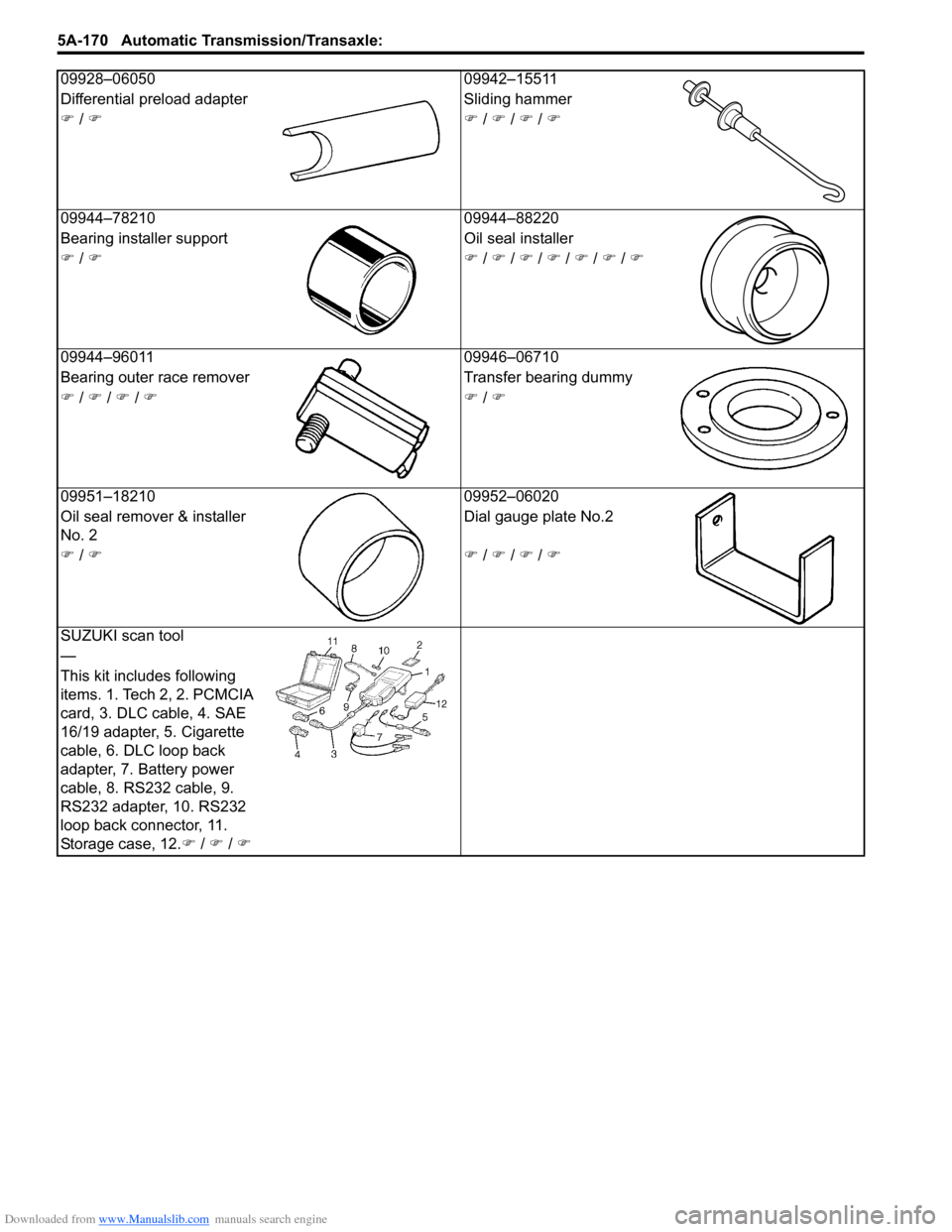
Downloaded from www.Manualslib.com manuals search engine 5A-170 Automatic Transmission/Transaxle:
09928–0605009942–15511
Differential preload adapter Sliding hammer
�) / �)�) / �) / �) / �)
09944–78210 09944–88220
Bearing installer sup port Oil seal installer
�) / �)�) / �) / �) / �) / �) / �) / �)
09944–96011 09946–06710
Bearing outer race remover Transfer bearing dummy
�) / �) / �) / �)�) / �)
09951–18210 09952–06020
Oil seal remover & installer
No. 2 Dial gauge plate No.2
�) / �)�) / �) / �) / �)
SUZUKI scan tool
—
This kit includes following
items. 1. Tech 2, 2. PCMCIA
card, 3. DLC cable, 4. SAE
16/19 adapter, 5. Cigarette
cable, 6. DLC loop back
adapter, 7. Battery power
cable, 8. RS232 cable, 9.
RS232 adapter, 10. RS232
loop back connector, 11.
Storage case, 12. �) / �) / �)
Page 834 of 1496
Downloaded from www.Manualslib.com manuals search engine 5B-20 Manual Transmission/Transaxle:
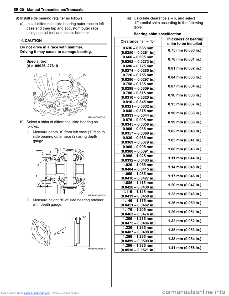
9) Install side bearing retainer as follows.a) Install differential side bearing outer race to left case and then tap and accustom outer race
using special tool and plastic hammer.
CAUTION!
Do not drive in a race with hammer.
Driving it may cause to damage bearing.
Special tool
(A): 09926–27610
b) Select a shim of differential side bearing as follows.
i) Measure depth “a” from left case (1) face to side bearing outer race (2) using depth
gauge.
ii) Measure height “b” of side bearing retainer with depth gauge. iii) Calculate clearance a – b, and select
differential shim acco rding to the following
table.
Bearing shim specification
(A)
I4RH01520053-01
I4RS0A520037-01
“b”
I4RS0A520038-01
Clearance “a” – “b” Thickness of bearing
shim to be installed
0.636 – 0.665 mm
(0.0250 – 0.0261 in.) 0.75 mm (0.030 in.)
0.666 – 0.695 mm
(0.0262 – 0.0273 in.) 0.78 mm (0.031 in.)
0.696 – 0.725 mm
(0.0274 – 0.0285 in.) 0.81 mm (0.032 in.)
0.726 – 0.755 mm
(0.0286 – 0.0297 in.) 0.84 mm (0.033 in.)
0.756 – 0.785 mm
(0.0298 – 0.0309 in.) 0.87 mm (0.034 in.)
0.786 – 0.815 mm
(0.0310 – 0.0320 in.) 0.90 mm (0.035 in.)
0.816 – 0.845 mm
(0.0321 – 0.0332 in.) 0.93 mm (0.037 in.)
0.846 – 0.875 mm
(0.0333 – 0.0344 in.) 0.96 mm (0.038 in.)
0.876 – 0.905 mm
(0.0345 – 0.0356 in.) 0.99 mm (0.039 in.)
0.906 – 0.935 mm
(0.0357 – 0.0368 in.) 1.02 mm (0.040 in.)
0.936 – 0.965 mm
(0.0369 – 0.0379 in.) 1.05 mm (0.041 in.)
0.966 – 0.995 mm
(0.0380 – 0.0391 in.) 1.08 mm (0.043 in.)
0.996 – 1.025 mm
(0.0392 – 0.0403 in.) 1.11 mm (0.044 in.)
1.026 – 1.055 mm
(0.0404 – 0.0415 in.) 1.14 mm (0.045 in.)
1.056 – 1.085 mm
(0.0416 – 0.0427 in.) 1.17 mm (0.046 in.)
1.086 – 1.115 mm
(0.0428 – 0.0438 in.) 1.20 mm (0.047 in.)
1.116 – 1.145 mm
(0.0439 – 0.0450 in.) 1.23 mm (0.048 in.)
1.146 – 1.175 mm
(0.0451 – 0.0462 in.) 1.26 mm (0.050 in.)
1.176 – 1.205 mm
(0.0463 – 0.0474 in.) 1.29 mm (0.051 in.)
1.206 – 1.235 mm
(0.0475 – 0.0486 in.) 1.32 mm (0.052 in.)
1.236 – 1.265 mm
(0.0487 – 0.0498 in.) 1.35 mm (0.053 in.)
1.266 – 1.295 mm
(0.0499 – 0.0509 in.) 1.38 mm (0.054 in.)
1.296 – 1.325 mm
(0.0510 – 0.0521 in.) 1.41 mm (0.056 in.)
Page 836 of 1496

Downloaded from www.Manualslib.com manuals search engine 5B-22 Manual Transmission/Transaxle:
14) With putting a shim (2) on bearing outer race (3), place straightedge (1) over it and compress it by
hand through straightedge, and then measure
clearance “a” between case surface (4) and
straightedge using feeler gauge (5).
Clearance between case surface and
straightedge (Shim protrusion)
“a”: 0.08 – 0.12 mm (0.0032 – 0.0047 in.)
15) By repeating Step 14), select a suitable shim which adjusts clearance “a” to specification and put it on
bearing outer race.
NOTE
Insert 0.10 mm (0.0039 in.) feeler to know
whether or not a shim fulfills specification
quickly.
Available shim thickness
16) Place left case plate (2) inserting its end in groove of shift guide shaft (4) and tighten bolts (1) to which
thread lock cement has been applied.
NOTE
After tightening bolts, make sure that
countershaft (5) can be rotated by hand
feeling certain load.
“A”: Thread lock cement 99000–32110 (Thread
Lock Cement Super 1322)
Tightening torque
Left case plate bolt (a): 23 N·m (2.3 kgf-m, 17.0
lb-ft)
17) Install fifth gear referring to “Fifth Gear Disassembly and Assembly”.
18) Install gear shift and select shaft assembly referring to “Gear Shift and Select Shaft Assembly Removal
and Installation”.
19) Install back up light switch referring to “Back Up Light
Switch Removal and Installation”.
20) Check input shaft for rotation in each gear position.
21) Also confirm continuity of back up light switch in
reverse position using ohmmeter.
0.55 mm (0.021 in.) 0.90 mm (0.035 in.)
0.60 mm (0.023 in.) 0.95 mm (0.037 in.)
0.65 mm (0.025 in.) 1.00 mm (0.039 in.)
0.70 mm (0.027 in.) 1.05 mm (0.041 in.)
0.75 mm (0.029 in.) 1.10 mm (0.043 in.)
0.80 mm (0.031 in.) 1.15 mm (0.059 in.)
0.85 mm (0.033 in.)
I3RM0A520031-01
3. Input shaft
I4RS0A520042-01