2005 SUZUKI SWIFT egr
[x] Cancel search: egrPage 412 of 1496
Downloaded from www.Manualslib.com manuals search engine 1J-2 Charging System:
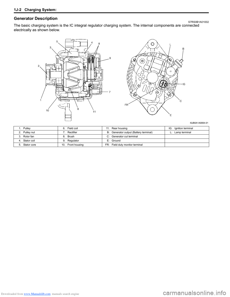
Generator DescriptionS7RS0B1A01002
The basic charging system is the IC integral regulator charging system. The internal co mponents are connected
electrically as shown below.
I5JB0A1A0004-01
1. Pulley 6. Field coil11. Rear housing IG: Ignition terminal
2. Pulley nut 7. RectifierB: Generator output (Battery terminal) L: Lamp terminal
3. Rotor fan 8. BrushC: Generator cut terminal
4. Stator coil 9. RegulatorE: Ground
5. Stator core 10. Front housing FR: Field duty monitor terminal
Page 473 of 1496

Downloaded from www.Manualslib.com manuals search engine Wheels and Tires: 2D-6
Repair Instructions
General Balance ProceduresS7RS0B2406001
Deposits of mud, etc. must be cleaned from inside of rim.
WARNING!
Stones should be removed from the tread in
order to avoid operator injury during spin
balancing and to obtain good balance.
Each tire should be inspected for any damage, then
balanced according to equipment manufacturer’s
recommendation.
Off-Vehicle Balancing
Most electronic off-vehicle balancers are more accurate
than the on-vehicle spin balancers. They are easy to use
and give a dynamic (two plane) balance. Although they
do not correct for drum or disc unbalance as does on-
vehicle spin balancing, this is overcome by their
accuracy, usually to within 1/8 ounce.
On-Vehicle Balancing
On-vehicle balancing methods vary with equipment and
tool manufacturers. Be sure to follow each
manufacturer’s instructions during balancing operation.
WARNING!
Wheel spin should be limited to 55 km/h (35
mph) as indicated on speedometer.
This limit is necessary because speedometer
only indicates one-half of actual wheel speed
when one drive wheel is spinning and the
other drive wheel is stopped.
Unless care is taken in limiting drive wheel
spin, spinning wheel can reach excessive
speeds. This can result in possible tire
disintegration or differential failure, which
could cause serious personal injury or
extensive vehicle damage.
CAUTION!
Using on-vehicle balancing method with
ignition switch ON may set malfunction
diagnostic trouble code (DTC) of ESP® and
ABS even when system is in good condition.
Never turn ignition swit ch ON while spinning
wheel.
Tire RotationS7RS0B2406002
To equalize wear, rotate tires according to figure. Radial
tires should be rotated periodi cally. Set tire pressure.
[A]: Rotation direction is not indicated.
[B]: Rotation direction is indicated.
I6RS0C240002-01
Page 484 of 1496
Downloaded from www.Manualslib.com manuals search engine 3A-6 Drive Shaft / Axle:
Front Drive Shaft Disassembly and ReassemblyS7RS0B3106004
Disassembly
Tripod joint
CAUTION!
• Disassembly of wheel side joint is not allowed. If any noise or damage exists in it,
replace it as assembly.
• Do not disassemble tripod joint spider. If any malcondition is found in it, replace it
as differential side joint assembly.
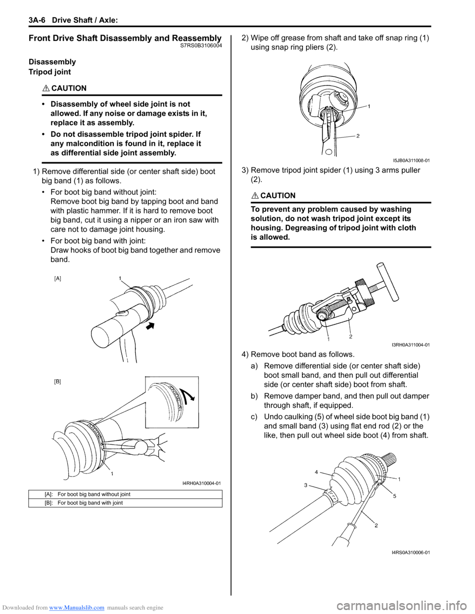
1) Remove differential side (or center shaft side) boot
big band (1) as follows.
• For boot big band without joint:Remove boot big band by tapping boot and band
with plastic hammer. If it is hard to remove boot
big band, cut it using a nipper or an iron saw with
care not to damage joint housing.
• For boot big band with joint: Draw hooks of boot big band together and remove
band. 2) Wipe off grease from shaft and take off snap ring (1)
using snap ring pliers (2).
3) Remove tripod joint spid er (1) using 3 arms puller
(2).
CAUTION!
To prevent any problem caused by washing
solution, do not wash tripod joint except its
housing. Degreasing of tr ipod joint with cloth
is allowed.
4) Remove boot band as follows.
a) Remove differential side (or center shaft side) boot small band, and then pull out differential
side (or center shaft side) boot from shaft.
b) Remove damper band, and then pull out damper through shaft, if equipped.
c) Undo caulking (5) of wheel side boot big band (1) and small band (3) using flat end rod (2) or the
like, then pull out wheel side boot (4) from shaft.
[A]: For boot big band without joint
[B]: For boot big band with joint
I4RH0A310004-01
I5JB0A311008-01
I3RH0A311004-01
I4RS0A310006-01
Page 486 of 1496
Downloaded from www.Manualslib.com manuals search engine 3A-8 Drive Shaft / Axle:
Reassembly
Tripod joint
Judging from abnormality noted before disassembly and
what is found through visual check of component parts
after disassembly, prepare replacing parts and proceed
to reassembly.
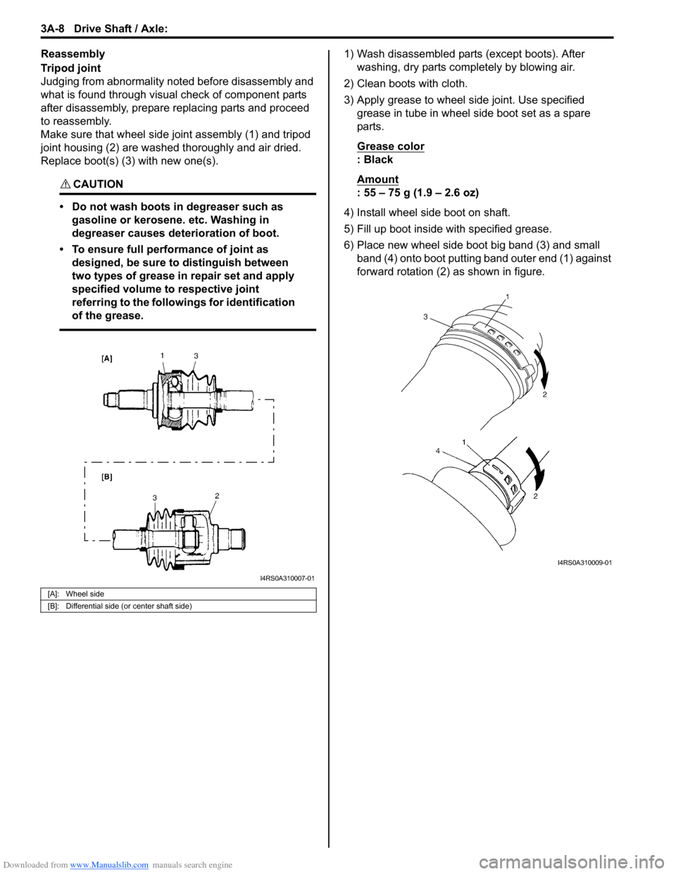
Make sure that wheel side joint assembly (1) and tripod
joint housing (2) are washed thoroughly and air dried.
Replace boot(s) (3) with new one(s).
CAUTION!
• Do not wash boots in degreaser such as gasoline or kerosene. etc. Washing in
degreaser causes deterioration of boot.
• To ensure full performance of joint as designed, be sure to distinguish between
two types of grease in repair set and apply
specified volume to respective joint
referring to the followings for identification
of the grease.
1) Wash disassembled parts (except boots). After washing, dry parts comp letely by blowing air.
2) Clean boots with cloth.
3) Apply grease to wheel side joint. Use specified grease in tube in wheel side boot set as a spare
parts.
Grease color
: Black
Amount
: 55 – 75 g (1.9 – 2.6 oz)
4) Install wheel side boot on shaft.
5) Fill up boot inside with specified grease.
6) Place new wheel side boot big band (3) and small band (4) onto boot putting band outer end (1) against
forward rotation (2) as shown in figure.
[A]: Wheel side
[B]: Differential side (or center shaft side)
I4RS0A310007-01
I4RS0A310009-01
Page 489 of 1496
Downloaded from www.Manualslib.com manuals search engine Drive Shaft / Axle: 3A-11
DOJ
Judging from abnormality noted before disassembly and
what is found through visual check of components parts
after disassembly, prepare replacing parts and proceed
to reassembly.
Make sure that wheel side joint assembly and DOJ
housing are washed thoroughly and air dried.
Replace boot(s) with new one(s).
CAUTION!
• Do not wash boots in degreaser such as gasoline or kerosene. etc. Washing in
degreaser causes deterioration of boot.
• To ensure full performance of joint as designed, be sure to distinguish between
two types of grease in repair set and apply
specified volume to respective joint
referring to the followings for identification
of the grease.
1) Wash disassembled parts (except boots). After washing, dry parts completely by blowing air.
2) Clean boots with cloth.
3) Apply grease to wheel side joint. Use specified
grease in tube in wheel side boot set as a spare
parts.
Grease color
: Black
Amount
: 55 – 75 g (1.9 – 2.6 oz)
4) Install wheel side boot on shaft.
5) Fill up boot inside wi th specified grease.
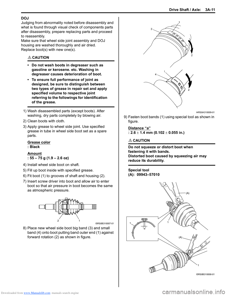
6) Fit boot (1) to grooves of shaft and housing (2).
7) Insert screw driver into boot and allow air to enter boot so that air pressure in boot becomes the same
as atmospheric pressure.
8) Place new wheel side boot big band (3) and small band (4) onto boot putting band outer end (1) against
forward rotation (2) as shown in figure. 9) Fasten boot bands (1) using special tool as shown in
figure.
Distance “a”
: 2.6 ± 1.4 mm (0.102 ± 0.055 in.)
CAUTION!
Do not squeeze or distort boot when
fastening it with bands.
Distorted boot caused by squeezing air may
reduce its durability.
Special tool
(A): 09943–57010
21I5RS0B310007-01
I4RS0A310009-01
(A)
1
(A)
1
“a”
1
I5RS0B310008-01
Page 526 of 1496
Downloaded from www.Manualslib.com manuals search engine 4C-2 Rear Brakes:
Rear Disc Brake Pad Removal and InstallationS7RS0B4306002
NOTE
When replacing brake pad, replace it on the
right and left.
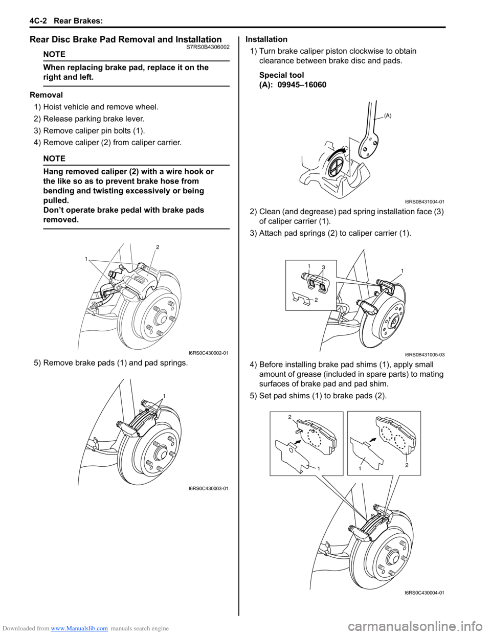
Removal1) Hoist vehicle and remove wheel.
2) Release parking brake lever.
3) Remove caliper pin bolts (1).
4) Remove caliper (2) from caliper carrier.
NOTE
Hang removed caliper (2) with a wire hook or
the like so as to prevent brake hose from
bending and twisting excessively or being
pulled.
Don’t operate brake pedal with brake pads
removed.
5) Remove brake pads (1) and pad springs. Installation
1) Turn brake caliper piston clockwise to obtain clearance between brake disc and pads.
Special tool
(A): 09945–16060
2) Clean (and degrease) pad spring installation face (3) of caliper carrier (1).
3) Attach pad springs (2) to caliper carrier (1).
4) Before installing brake p ad shims (1), apply small
amount of grease (included in spare parts) to mating
surfaces of brake pad and pad shim.
5) Set pad shims (1) to brake pads (2).
1 2
I6RS0C430002-01
1
I6RS0C430003-01
(A)
I6RS0B431004-01
113
2
I6RS0B431005-03
2
1
1 2
I6RS0C430004-01
Page 677 of 1496
Downloaded from www.Manualslib.com manuals search engine Automatic Transmission/Transaxle: 5A-33
Troubleshooting
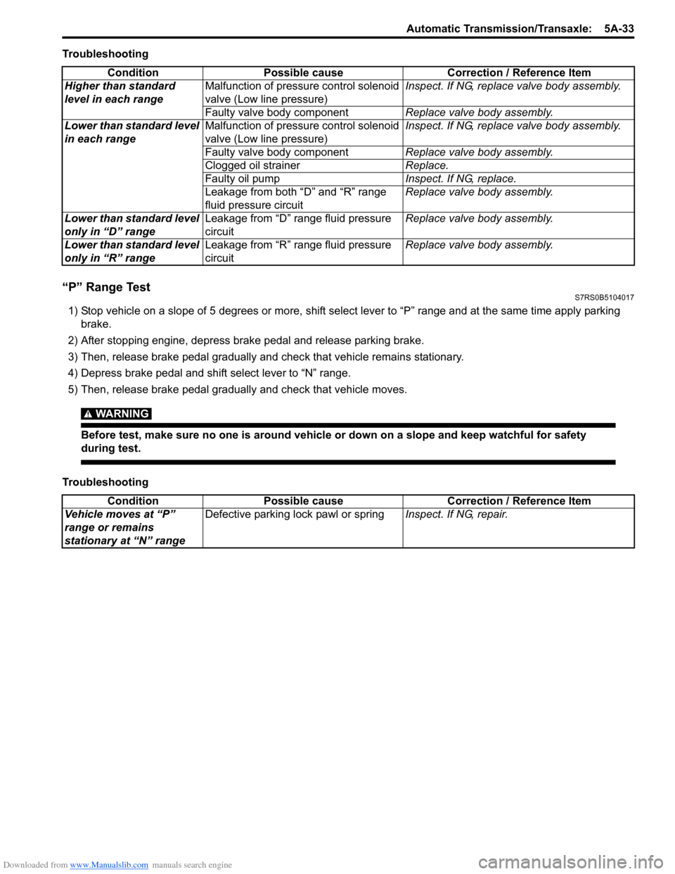
“P” Range TestS7RS0B5104017
1) Stop vehicle on a slope of 5 degrees or more, shift select lever to “P” range and at the same time apply parking brake.
2) After stopping engine, depress brake pedal and release parking brake.
3) Then, release brake pedal gradually and check that vehicle remains stationary.
4) Depress brake pedal and shift select lever to “N” range.
5) Then, release brake pedal gradually and check that vehicle moves.
WARNING!
Before test, make sure no one is around vehicle or down on a slope and keep watchful for safety
during test.
Troubleshooting Condition Possible cause Correction / Reference Item
Higher than standard
level in each range Malfunction of pressure control solenoid
valve (Low line pressure) Inspect. If NG, replace valve body assembly.
Faulty valve body component Replace valve body assembly.
Lower than standard level
in each range Malfunction of pressure control solenoid
valve (Low line pressure) Inspect. If NG, replace valve body assembly.
Faulty valve body component Replace valve body assembly.
Clogged oil strainer Replace.
Faulty oil pump Inspect. If NG, replace.
Leakage from both “D” and “R” range
fluid pressure circuit Replace valve body assembly.
Lower than standard level
only in “D” range Leakage from “D” range fluid pressure
circuit Replace valve body assembly.
Lower than standard level
only in “R” range Leakage from “R” range fluid pressure
circuit Replace valve body assembly.
Condition
Possible cause Correction / Reference Item
Vehicle moves at “P”
range or remains
stationary at “N” range Defective parking lock pawl or spring
Inspect. If NG, repair.
Page 952 of 1496
Downloaded from www.Manualslib.com manuals search engine 7B-4 Air Conditioning System: Manual Type
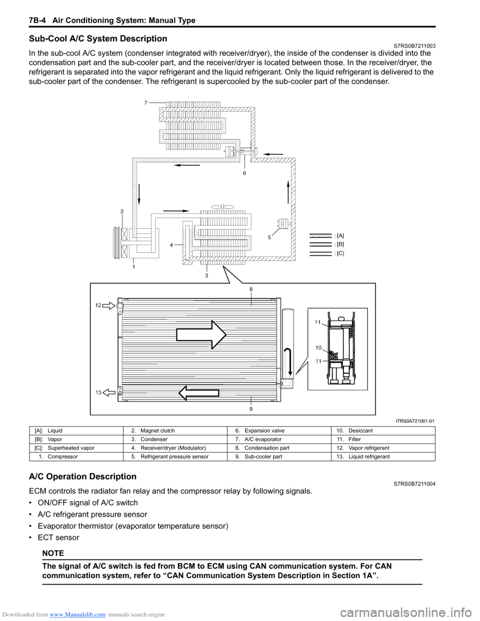
Sub-Cool A/C System DescriptionS7RS0B7211003
In the sub-cool A/C system (condenser integrated with receiver/dryer), the inside of the condenser is divided into the
condensation part and the sub-cooler part, and the receiver/dryer is located between those. In the receiver/dryer, the
refrigerant is separated into the vapor refrigerant and the liqui d refrigerant. Only the liquid refrigerant is delivered to the
sub-cooler part of the condenser. The refrigerant is supercooled by the sub-cooler part of the condenser.
A/C Operation DescriptionS7RS0B7211004
ECM controls the radiator fan relay and the compressor relay by following signals.
• ON/OFF signal of A/C switch
• A/C refrigerant pressure sensor
• Evaporator thermistor (evaporator temperature sensor)
• ECT sensor
NOTE
The signal of A/C swit ch is fed from BCM to ECM usin g CAN communication system. For CAN
communication system, refer to “CAN Communication System Description in Section 1A”.
I7RS0A721001-01
[A]: Liquid 2. Magnet clutch 6. Expansion valve10. Desiccant
[B]: Vapor 3. Condenser 7. A/C evaporator11. Filter
[C]: Superheated vapor 4. Receiver/dryer (Modulator) 8. Condensation part12. Vapor refrigerant
1. Compressor 5. Refrigerant pressure sensor 9. Sub-cooler part 13. Liquid refrigerant