2005 SUZUKI SWIFT O2 sensor
[x] Cancel search: O2 sensorPage 1115 of 1496
Downloaded from www.Manualslib.com manuals search engine Air Bag System: 8B-77
CAUTION!
• Be sure to perform “Air Bag Diagnostic System Check” before starting diagnosis according to flow.
• When measurement of resistance or voltage is required in this flow, use a tester along with a correct terminal adapter from special tool (Connector test adapter kit).
• When a check for proper connection is required, refer to “Inspection of Intermittent and Poor Connections”.
• If there is open circuit in the air bag wire harnes s, connector or terminal is found damaged, replace
the wire harness, connector and terminal as an assembly.
DTC Will Set when
Forward-sensor abnormal signal is detected by SDM.
Flow Test Description
Step 1: Check for short circuit between forward-sensor circuit and ground.
Step 2: Check if malfuncti on is in forward-sensor.
DTC Troubleshooting
NOTE
Upon completion of inspection and repair work, perform the following items.
• Reconnect all air bag system components and ensure all components are properly mounted.
• Clear DTCs referring to “DTC Clearance”, if any.
• Repeat “Air Bag Diagnostic System Check” to confirm that the trouble has been corrected.
Step Action YesNo
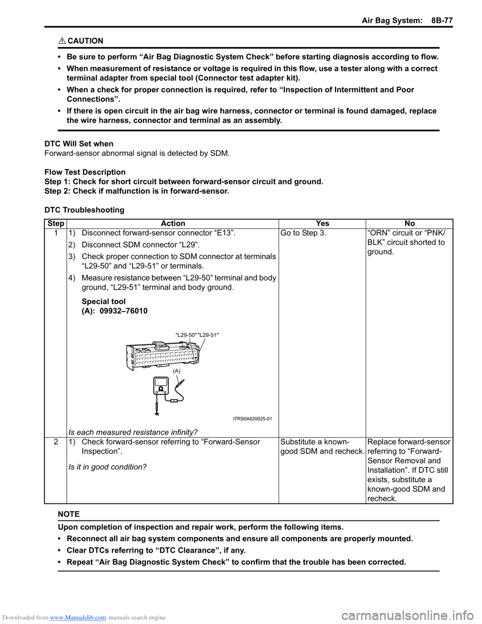
1 1) Disconnect forward-sensor connector “E13”.
2) Disconnect SDM connector “L29”.
3) Check proper connection to SDM connector at terminals “L29-50” and “L29-51” or terminals.
4) Measure resistance between “L29-50” terminal and body ground, “L29-51” terminal and body ground.
Special tool
(A): 09932–76010
Is each measured resistance infinity? Go to Step 3.
“ORN” circuit or “PNK/
BLK” circuit shorted to
ground.
2 1) Check forward-sensor referring to “Forward-Sensor Inspection”.
Is it in good condition? Substitute a known-
good SDM and recheck.
Replace forward-sensor
referring to “Forward-
Sensor Removal and
Installation”. If DTC still
exists, substitute a
known-good SDM and
recheck.
"L29-50" "L29-51"
(A)
I7RS0A820025-01
Page 1116 of 1496
Downloaded from www.Manualslib.com manuals search engine 8B-78 Air Bag System:
DTC B1074: Forward-Sensor Circuit Short to Power Circuit or OpenS7RS0B8204037
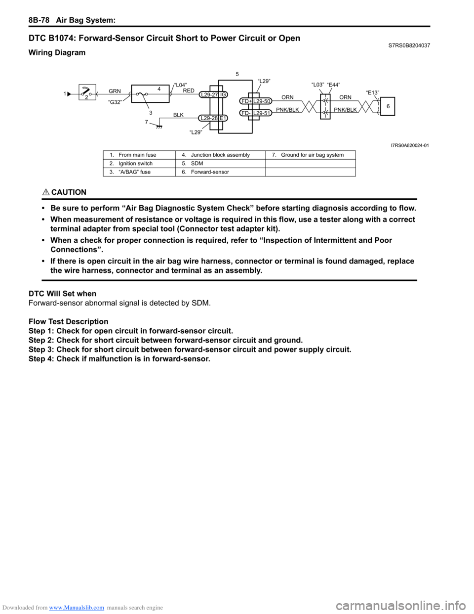
Wiring Diagram
CAUTION!
• Be sure to perform “Air Bag Diagnostic System Check” before starting diagnosis according to flow.
• When measurement of resistance or voltage is required in this flow, use a tester along with a correct terminal adapter from special tool (Connector test adapter kit).
• When a check for proper connection is required, refer to “Inspection of Intermittent and Poor Connections”.
• If there is open circuit in the air bag wire harnes s, connector or terminal is found damaged, replace
the wire harness, connector and terminal as an assembly.
DTC Will Set when
Forward-sensor abnormal signal is detected by SDM.
Flow Test Description
Step 1: Check for open circuit in forward-sensor circuit.
Step 2: Check for short circuit between forward-sensor circuit and ground.
Step 3: Check for short circuit between forw ard-sensor circuit and power supply circuit.
Step 4: Check if malfuncti on is in forward-sensor.
1
2
3
GRN
RED
7
BLK
L29-27
L29-28 IG
E1
4
“L29”
“L04”
“G32”
“L29”5
ORN
PNK/BLK
ORN
PNK/BLKL29-50
FD+
L29-51
FD-6
“E13”
“L03”“E44”
I7RS0A820024-01
1. From main fuse 4. Junction block assembly 7. Ground for air bag system
2. Ignition switch 5. SDM
3. “A/BAG” fuse 6. Forward-sensor
Page 1117 of 1496
Downloaded from www.Manualslib.com manuals search engine Air Bag System: 8B-79
DTC Troubleshooting
NOTE
Upon completion of inspection and repair work, perform the following items.
• Reconnect all air bag system components and ensure all components are properly mounted.
• Clear DTCs referring to “DTC Clearance”, if any.
• Repeat “Air Bag Diagnostic System Check” to confirm that the trouble has been corrected.
StepAction YesNo
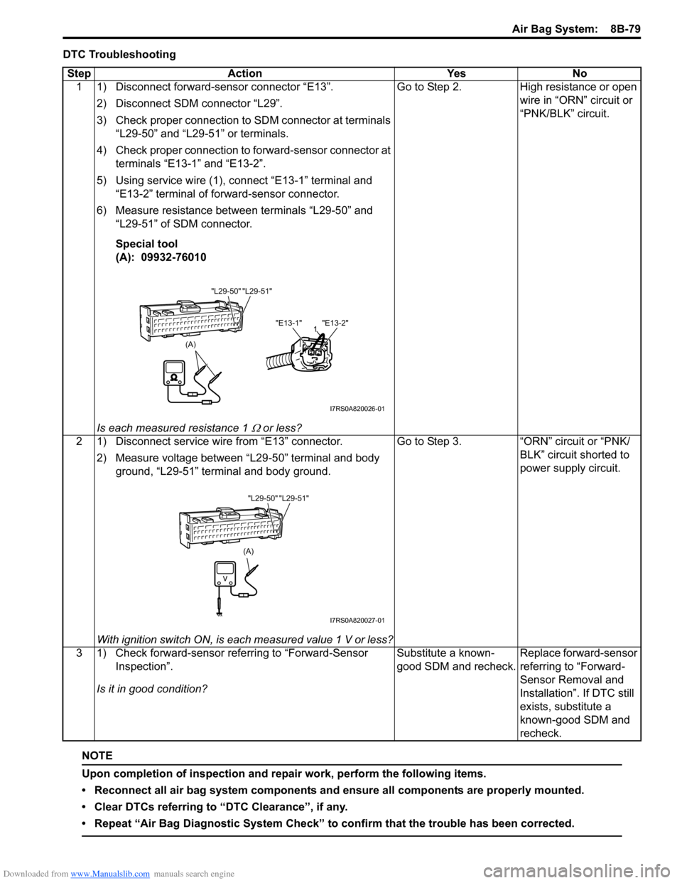
1 1) Disconnect forward-sensor connector “E13”.
2) Disconnect SDM connector “L29”.
3) Check proper connection to SDM connector at terminals “L29-50” and “L29-51” or terminals.
4) Check proper connection to forward-sensor connector at terminals “E13-1” and “E13-2”.
5) Using service wire (1), connect “E13-1” terminal and “E13-2” terminal of forward-sensor connector.
6) Measure resistance between terminals “L29-50” and “L29-51” of SDM connector.
Special tool
(A): 09932-76010
Is each measured resistance 1
Ω or less? Go to Step 2. High resistance or open
wire in “ORN” circuit or
“PNK/BLK” circuit.
2 1) Disconnect service wire from “E13” connector. 2) Measure voltage between “L29-50” terminal and body ground, “L29-51” terminal and body ground.
With ignition switch ON, is each measured value 1 V or less? Go to Step 3. “ORN” circuit or “PNK/
BLK” circuit shorted to
power supply circuit.
3 1) Check forward-sensor referring to “Forward-Sensor Inspection”.
Is it in good condition? Substitute a known-
good SDM and recheck.
Replace forward-sensor
referring to “Forward-
Sensor Removal and
Installation”. If DTC still
exists, substitute a
known-good SDM and
recheck.
(A)
"L29-50" "L29-51"
"E13-1" "E13-2"1
I7RS0A820026-01
"L29-50" "L29-51"
(A)
I7RS0A820027-01
Page 1118 of 1496
Downloaded from www.Manualslib.com manuals search engine 8B-80 Air Bag System:
DTC B1081 / B1091: Driver / Passenger Side-Sensor Performance ProblemS7RS0B8204038
DTC Will Set when
SDM receives internal fault signal from side-sensor.
DTC Troubleshooting1) Turn ignition switch OFF.
2) Replace driver or passenger side-sensor referr ing to “Side-Sensor Removal and Installation”.
3) Repeat “Air Bag Diagnostic System Check”.
DTC B1082 / B1092: Driver / Passenger Side-Sensor Communication ErrorS7RS0B8204039
DTC Will Set when
Side-sensor abnormal signal is detected by SDM.
DTC Troubleshooting
1) Turn ignition switch OFF.
2) Replace driver or passenger side-sensor referr ing to “Side-Sensor Removal and Installation”.
3) Repeat “Air Bag Diagnostic System Check”.
DTC B1083 / B1093: Driver / Passenger Side-Sensor Circuit Short to GroundS7RS0B8204040
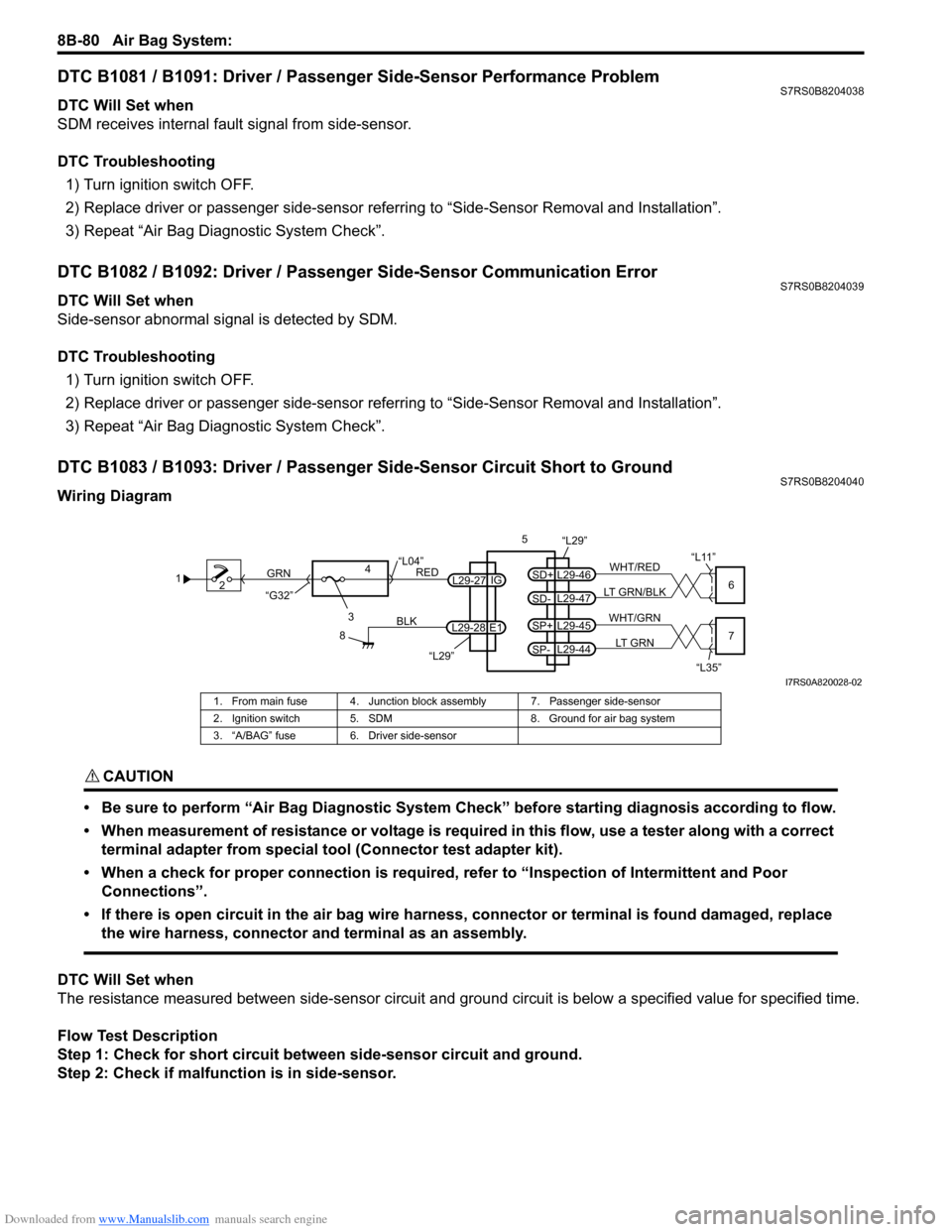
Wiring Diagram
CAUTION!
• Be sure to perform “Air Bag Diagnostic System Check” before starting diagnosis according to flow.
• When measurement of resistance or voltage is required in this flow, use a tester along with a correct terminal adapter from special tool (Connector test adapter kit).
• When a check for proper connection is required, refer to “Inspection of Intermittent and Poor Connections”.
• If there is open circuit in the air bag wire harnes s, connector or terminal is found damaged, replace
the wire harness, connector and terminal as an assembly.
DTC Will Set when
The resistance measured between side-sen sor circuit and ground circuit is below a specified value for specified time.
Flow Test Description
Step 1: Check for short circuit between side-sensor circuit and ground.
Step 2: Check if malfunction is in side-sensor.
1 2
3
GRN
RED
8
BLK
L29-27
L29-28 IG
E1
4
“L29”
“L04”
“G32”
“L29”5
WHT/RED
LT GRN/BLKL29-46
SD+
L29-47
SD-6
“L11”
WHT/GRN
LT GRNL29-45
SP+
L29-44
SP-7
“L35”
I7RS0A820028-02
1. From main fuse 4. Junction blo ck assembly 7. Passenger side-sensor
2. Ignition switch 5. SDM 8. Ground for air bag system
3. “A/BAG” fuse 6. Driver side-sensor
Page 1119 of 1496
Downloaded from www.Manualslib.com manuals search engine Air Bag System: 8B-81
DTC Troubleshooting
NOTE
Upon completion of inspection and repair work, perform the following items.
• Reconnect all air bag system components and ensure all components are properly mounted.
• Clear DTCs referring to “DTC Clearance”, if any.
• Repeat “Air Bag Diagnostic System Check” to confirm that the trouble has been corrected.
DTC B1084 / B1094: Driver / Passenger Side-Sensor Circuit Short to Power Circuit or OpenS7RS0B8204041
Wiring DiagramStep Action Yes No
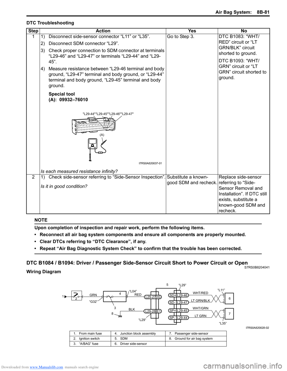
1 1) Disconnect side-sensor connector “L11” or “L35”.
2) Disconnect SDM connector “L29”.
3) Check proper connection to SDM connector at terminals “L29-46” and “L29-47” or terminals “L29-44” and “L29-
45”.
4) Measure resistance between “L29-46 terminal and body ground, “L29-47” terminal and body ground, or “L29-44”
terminal and body ground, “L29-45” terminal and body
ground.
Special tool
(A): 09932–76010
Is each measured resistance infinity? Go to Step 3. DTC B1083: “WHT/
RED” circuit or “LT
GRN/BLK” circuit
shorted to ground.
DTC B1093: “WHT/
GRN” circuit or “LT
GRN” circuit shorted to
ground.
2 1) Check side-sensor referring to “Side-Sensor Inspection”. Is it in good condition? Substitute a known-
good SDM and recheck.
Replace side-sensor
referring to “Side-
Sensor Removal and
Installation”. If DTC still
exists, substitute a
known-good SDM and
recheck.
"L29-45""L29-46""L29-47"
"L29-44"
(A)
I7RS0A820037-01
12
3
GRN
RED
8
BLK
L29-27
L29-28 IG
E1
4
“L29”
“L04”
“G32”
“L29”5
WHT/RED
LT GRN/BLKL29-46
SD+
L29-47
SD-6
“L11”
WHT/GRN
LT GRNL29-45
SP+
L29-44
SP-7
“L35”
I7RS0A820028-02
1. From main fuse 4. Junction blo ck assembly 7. Passenger side-sensor
2. Ignition switch 5. SDM 8. Ground for air bag system
3. “A/BAG” fuse 6. Driver side-sensor
Page 1120 of 1496
Downloaded from www.Manualslib.com manuals search engine 8B-82 Air Bag System:
CAUTION!
• Be sure to perform “Air Bag Diagnostic System Check” before starting diagnosis according to flow.
• When measurement of resistance or voltage is required in this flow, use a tester along with a correct terminal adapter from special tool (Connector test adapter kit).
• When a check for proper connection is required, refer to “Inspection of Intermittent and Poor Connections”.
• If there is open circuit in the air bag wire harnes s, connector or terminal is found damaged, replace
the wire harness, connector and terminal as an assembly.
DTC Will Set when
The resistance measured between side-sensor circuit and power source circuit is below a specified value for specified
time.
Flow Test Description
Step 1: Check for open circuit in side-sensor circuit.
Step 2: Check for short circuit between side-sensor circuit and power supply circuit.
Step 3: Check if malfunction is in side-sensor.
DTC Troubleshooting
Step Action YesNo
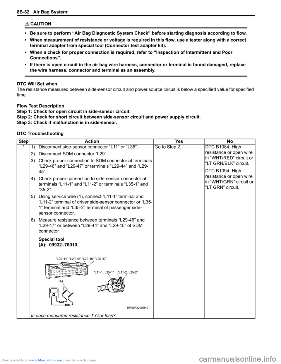
1 1) Disconnect side-sensor connector “L11” or “L35”.
2) Disconnect SDM connector “L29”.
3) Check proper connection to SDM connector at terminals “L29-46” and “L29-47” or terminals “L29-44” and “L29-
45”.
4) Check proper connection to side-sensor connector at terminals “L11-1” and “L11-2” or terminals “L35-1” and
“35-2”.
5) Using service wire (1), connect “L11-1” terminal and “L11-2” terminal of driver side-sensor connector or “L35-
1” terminal and “L35-2” terminal of passenger side-
sensor connector.
6) Measure resistance between terminals “L29-46” and “L29-47” or between “L29-44” and “L29-45” of SDM
connector.
Special tool
(A): 09932–76010
Is each measured resistance 1
Ω or less? Go to Step 2. DTC B1084: High
resistance or open wire
in “WHT/RED” circuit or
“LT GRN/BLK” circuit.
DTC B1094: High
resistance or open wire
in “WHT/GRN” circuit or
“LT GRN” circuit.
(A)
"L11-1, L35-1" "L11-2, L35-2"1
"L29-45" "L29-46" "L29-47"
"L29-44"
I7RS0A820029-01
Page 1121 of 1496
Downloaded from www.Manualslib.com manuals search engine Air Bag System: 8B-83
NOTE
Upon completion of inspection and repair work, perform the following items.
• Reconnect all air bag system components and ensure all components are properly mounted.
• Clear DTCs referring to “DTC Clearance”, if any.
• Repeat “Air Bag Diagnostic System Check” to confirm that the trouble has been corrected.
DTC B1085 / B1095: Wrong Side-Sensor (Driver Side / Passenger) IDS7RS0B8204042
DTC Will Set when
SDM receives wrong ID (Part No.) signal from side-sensor.
DTC Troubleshooting1) Turn ignition switch OFF.
2) Replace driver or passenger side-sensor referr ing to “Side-Sensor Removal and Installation”.
3) Repeat “Air Bag Diagnostic System Check”.
NOTE
Upon completion of inspection and repair work, perform the following items.
• Reconnect all air bag system components and ensure all components are properly mounted.
• Clear DTCs referring to “DTC Clearance”, if any.
• Repeat “Air Bag Diagnostic System Check” to confirm that the trouble has been corrected.
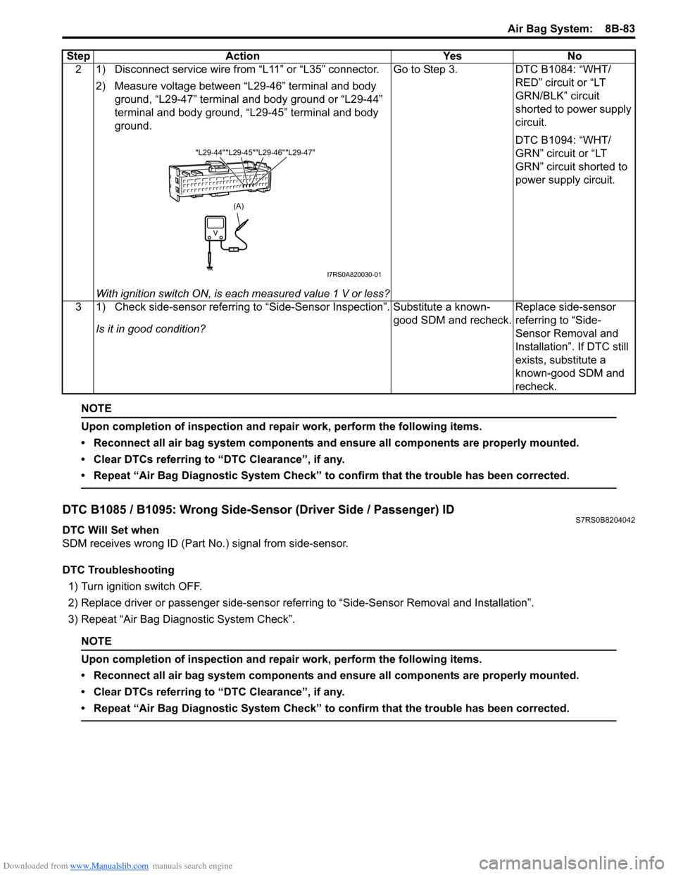
2 1) Disconnect service wire from “L11” or “L35” connector.
2) Measure voltage between “L29-46” terminal and body ground, “L29-47” terminal and body ground or “L29-44”
terminal and body ground, “L29-45” terminal and body
ground.
With ignition switch ON, is each measured value 1 V or less? Go to Step 3. DTC B1084: “WHT/
RED” circuit or “LT
GRN/BLK” circuit
shorted to power supply
circuit.
DTC B1094: “WHT/
GRN” circuit or “LT
GRN” circuit shorted to
power supply circuit.
3 1) Check side-sensor referring to “Side-Sensor Inspection”. Is it in good condition? Substitute a known-
good SDM and recheck.
Replace side-sensor
referring to “Side-
Sensor Removal and
Installation”. If DTC still
exists, substitute a
known-good SDM and
recheck.
Step Action Yes No
(A)
"L29-45""L29-46" "L29-47"
"L29-44"
I7RS0A820030-01
Page 1134 of 1496
Downloaded from www.Manualslib.com manuals search engine 8B-96 Air Bag System:
Repair and Inspection Required after AccidentS7RS0B8204049
CAUTION!
• All air bag system components, including the electrical harness (component
mounting points), must be inspected after
an accident. If any components are
damaged or bent, they must be replaced
even if air bag system activation did not
occur.
• Never use air bag system parts from another vehicle.
• Do not attempt to service the parts below. Service of these parts is by replacement
only.
– Driver / Passenger air bag (inflator) modules
– Driver / Passenger side-air bag (inflator) modules
– Driver / Passenger side curtain-air bag (inflator) modules
– Driver / Passenger seat belt pretensioners
–Forward-sensor
– Driver / Passenger side-sensors
–SDM
– Contact coil and combination switch assembly
– Air bag wire harness in main harness, instrument panel harness and floor
harness.
• Proper operation of the sensors and air bag system requires that any repairs to the
vehicle structure return it to its original
production configuration.
CAUTION!
After detecting one time of such collision as
to meet deployment conditions, the SDM
must not be used.
Refer to “Air Bag Diagnostic System Check”
when checking the SDM.
Accident with Deployment / Activation – Component
Replacement
When driver and passenger air bags are deployed, the
following components must be replaced.
• Driver and passenger air bag (inflator) modules
• Driver and passenger seat belt pretensioners
• SDM after detecting such collision as to meet
deployment conditions
• Forward-sensor
• Instrument panel When side-air bag and side curtain-air bag are deployed,
the following components must be replaced.
• Deployed side-air bag (inflator) module
• Deployed side curtain-air bag (inflator) module
• Side-sensor
•SDM
Accident with or without Deployment / Activation –
Component Inspections
Certain air bag and restraint system components must
be inspected after any crash, whether the air bag system
activated or not. If any faul
ty condition is found in the
following checks, replace faulty part.
Those components are:
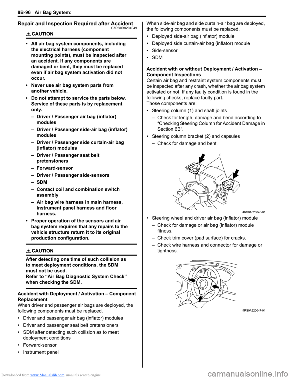
• Steering column (1) and shaft joints
– Check for length, damage and bend according to “Checking Steering Column for Accident Damage in
Section 6B”.
• Steering column bracket (2) and capsules – Check for damage and bent.
• Steering wheel and driver air bag (inflator) module – Check for damage or air bag (inflator) module fitness.
– Check trim cover (pad surface) for cracks.
– Check wire harness and connector for damage or tightness.
2
1
I4RS0A820046-01
I4RS0A820047-01