2005 SUZUKI SWIFT Inspection
[x] Cancel search: InspectionPage 714 of 1496

Downloaded from www.Manualslib.com manuals search engine 5A-70 Automatic Transmission/Transaxle:
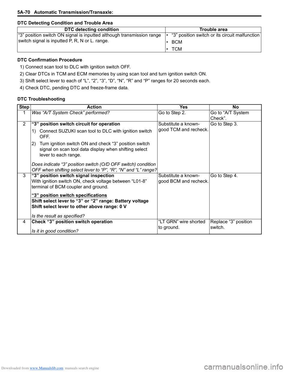
DTC Detecting Condition and Trouble Area
DTC Confirmation Procedure
1) Connect scan tool to DLC with ignition switch OFF.
2) Clear DTCs in TCM and ECM memories by us ing scan tool and turn ignition switch ON.
3) Shift select lever to each of “L”, “2”, “3”, “D”, “N”, “R” and “P” ranges for 20 seconds each.
4) Check DTC, pending DTC and freeze-frame data.
DTC Troubleshooting DTC detecting condition Trouble area
“3” position switch ON signal is inputted although transmission range
switch signal is inputted P, R, N or L. range. • “3” position switch or its circuit malfunction
•BCM
•TCM
Step
Action YesNo
1 Was “A/T System Check” performed? Go to Step 2.Go to “A/T System
Check”.
2 “3” position switch circuit for operation
1) Connect SUZUKI scan tool to DLC with ignition switch
OFF.
2) Turn ignition switch ON and check “3” position switch signal on scan tool data display when shifting select
lever to each range.
Does indicate “3” position swit ch (O/D OFF switch) condition
OFF when shifting select lever to “P”, “R”, “N” and “L” range? Substitute a known-
good TCM and recheck.
Go to Step 3.
3 “3” position switch signal inspection
With ignition switch ON, check voltage between “L01-8”
terminal of BCM coupler and ground.
“3” position switch specifications
Shift select lever to “3” or “2” range: Battery voltage
Shift select lever to other above range: 0 V
Is the result as specified? Substitute a known-
good BCM and recheck.
Go to Step 4.
4 Check “3” position switch operation
Is it in good condition? “LT GRN” wire shorted
to ground.
Replace “3” position
switch.
Page 716 of 1496

Downloaded from www.Manualslib.com manuals search engine 5A-72 Automatic Transmission/Transaxle:
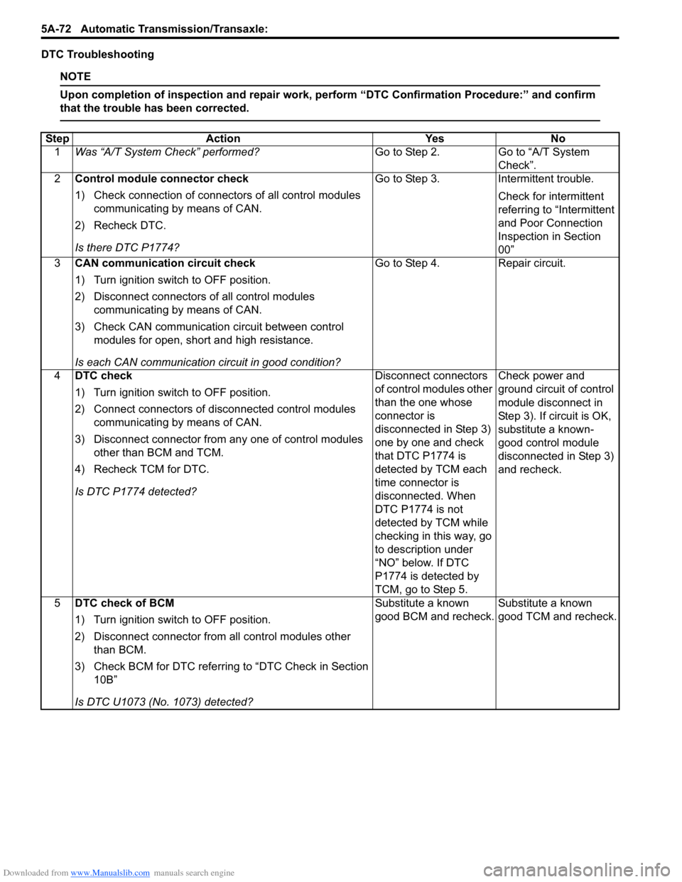
DTC Troubleshooting
NOTE
Upon completion of inspection and repair work, perform “DTC Confirmation Procedure:” and confirm
that the trouble has been corrected.
Step Action YesNo
1 Was “A/T System Check” performed? Go to Step 2.Go to “A/T System
Check”.
2 Control module connector check
1) Check connection of connectors of all control modules
communicating by means of CAN.
2) Recheck DTC.
Is there DTC P1774? Go to Step 3.
Intermittent trouble.
Check for intermittent
referring to “Intermittent
and Poor Connection
Inspection in Section
00”
3 CAN communication circuit check
1) Turn ignition switch to OFF position.
2) Disconnect connectors of all control modules
communicating by means of CAN.
3) Check CAN communication circuit between control modules for open, short and high resistance.
Is each CAN communication circuit in good condition? Go to Step 4.
Repair circuit.
4 DTC check
1) Turn ignition switch to OFF position.
2) Connect connectors of disconnected control modules
communicating by means of CAN.
3) Disconnect connector from any one of control modules other than BCM and TCM.
4) Recheck TCM for DTC.
Is DTC P1774 detected? Disconnect connectors
of control modules other
than the one whose
connector is
disconnected in Step 3)
one by one and check
that DTC P1774 is
detected by TCM each
time connector is
disconnected. When
DTC P1774 is not
detected by TCM while
checking in this way, go
to description under
“NO” below. If DTC
P1774 is detected by
TCM, go to Step 5.Check power and
ground circuit of control
module disconnect in
Step 3). If circuit is OK,
substitute a known-
good control module
disconnected in Step 3)
and recheck.
5 DTC check of BCM
1) Turn ignition switch to OFF position.
2) Disconnect connector from all control modules other
than BCM.
3) Check BCM for DTC referring to “DTC Check in Section 10B”
Is DTC U1073 (No. 1073) detected? Substitute a known
good BCM and recheck.
Substitute a known
good TCM and recheck.
Page 717 of 1496

Downloaded from www.Manualslib.com manuals search engine Automatic Transmission/Transaxle: 5A-73
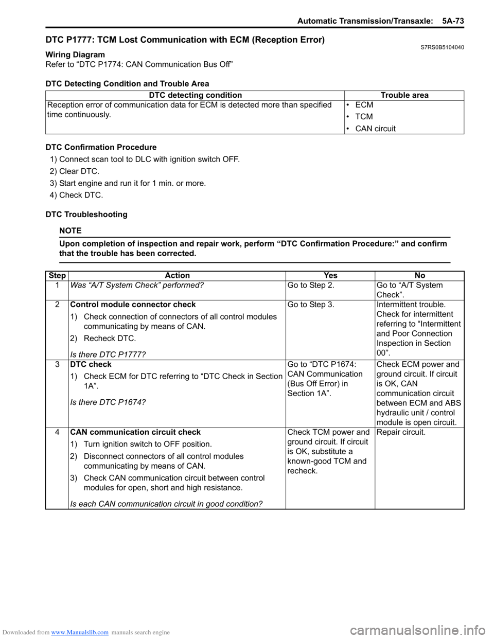
DTC P1777: TCM Lost Communication with ECM (Reception Error)S7RS0B5104040
Wiring Diagram
Refer to “DTC P1774: CAN Communication Bus Off”
DTC Detecting Condition and Trouble Area
DTC Confirmation Procedure1) Connect scan tool to DLC with ignition switch OFF.
2) Clear DTC.
3) Start engine and run it for 1 min. or more.
4) Check DTC.
DTC Troubleshooting
NOTE
Upon completion of inspection and repair work, perform “DTC Confirmation Procedure:” and confirm
that the trouble has been corrected.
DTC detecting condition Trouble area
Reception error of communication data fo r ECM is detected more than specified
time continuously. •ECM
•TCM
• CAN circuit
Step
Action YesNo
1 Was “A/T System Check” performed? Go to Step 2.Go to “A/T System
Check”.
2 Control module connector check
1) Check connection of connectors of all control modules
communicating by means of CAN.
2) Recheck DTC.
Is there DTC P1777? Go to Step 3.
Intermittent trouble.
Check for intermittent
referring to “Intermittent
and Poor Connection
Inspection in Section
00”.
3 DTC check
1) Check ECM for DTC referring to “DTC Check in Section
1A”.
Is there DTC P1674? Go to “DTC P1674:
CAN Communication
(Bus Off Error) in
Section 1A”.
Check ECM power and
ground circuit. If circuit
is OK, CAN
communication circuit
between ECM and ABS
hydraulic unit / control
module is open circuit.
4 CAN communication circuit check
1) Turn ignition switch to OFF position.
2) Disconnect connectors of all control modules
communicating by means of CAN.
3) Check CAN communication circuit between control modules for open, short and high resistance.
Is each CAN communication circuit in good condition? Check TCM power and
ground circuit. If circuit
is OK, substitute a
known-good TCM and
recheck.
Repair circuit.
Page 718 of 1496

Downloaded from www.Manualslib.com manuals search engine 5A-74 Automatic Transmission/Transaxle:
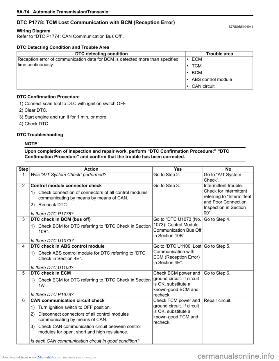
DTC P1778: TCM Lost Communication with BCM (Reception Error)S7RS0B5104041
Wiring Diagram
Refer to “DTC P1774: CAN Communication Bus Off”.
DTC Detecting Condition and Trouble Area
DTC Confirmation Procedure
1) Connect scan tool to DLC with ignition switch OFF.
2) Clear DTC.
3) Start engine and run it for 1 min. or more.
4) Check DTC.
DTC Troubleshooting
NOTE
Upon completion of inspection and repair work, perform “DTC Confirmation Procedure:” “DTC
Confirmation Procedure” and confirm that the trouble has been corrected.
DTC detecting condition Trouble area
Reception error of communication data fo r BCM is detected more than specified
time continuously. •ECM
•TCM
•BCM
• ABS control module
• CAN circuit
Step
Action YesNo
1 Was “A/T System Check” performed? Go to Step 2.Go to “A/T System
Check”.
2 Control module connector check
1) Check connection of connectors of all control modules
communicating by means by means of CAN.
2) Recheck DTC.
Is there DTC P1778? Go to Step 3.
Intermittent trouble.
Check for intermittent
referring to “Intermittent
and Poor Connection
Inspection in Section
00”.
3 DTC check in BCM (bus off)
1) Check BCM for DTC referring to “DTC Check in Section
10B”.
Is there DTC U1073? Go to “DTC U1073 (No.
1073): Control Module
Communication Bus Off
in Section 10B”.
Go to Step 4.
4 DTC check in ABS control module
1) Check ABS control module for DTC referring to “DTC
Check in Section 4E”.
Is there DTC U1100? Go to “DTC U1100: Lost
Communication with
ECM (Reception Error)
in Section 4E”.
Go to Step 5.
5 DTC check in ECM
1) Check ECM for DTC referring to “DTC Check in Section
1A”.
Is there DTC P1678? Check BCM power and
ground circuit. If circuit
is OK, substitute a
known-good BCM and
recheck.Go to Step 6.
6 CAN communication circuit check
1) Turn ignition switch to OFF position.
2) Disconnect connectors of all control modules
communicating by means of CAN.
3) Check CAN communication circuit between control modules for open, short and high resistance.
Is each CAN communication circuit in good condition? Check TCM power and
ground circuit. If circuit
is OK, substitute a
known-good TCM and
recheck.
Repair circuit.
Page 721 of 1496

Downloaded from www.Manualslib.com manuals search engine Automatic Transmission/Transaxle: 5A-77
DTC TroubleshootingStep Action Yes No 1 Was “A/T System Check” performed? Go to Step 2. Go to “A/T System
Check”.
2 Check TCC solenoid valve resistance
1) Turn ignition switch to OFF position.
2) Disconnect valve body harness connector (1), (2) on
automatic transaxle.
3) Check for proper connection to terminal at “WHT/BLU” and “WHT/BLK” circuit.
4) Check resistance of TCC solenoid valve.
TCC solenoid valve resistance
Between terminals of transaxle side valve body
harness connector: 5.0 – 5.6 Ω at 20 °C (68 °F)
Between terminals of transaxle side valve body
harness connector and transaxle: Infinity
Is check results satisfactory? Go to Step 3. Replace TCC solenoid
valve or valve body
harness.
3 Check for pressure control solenoid valve circuit
1) Disconnect TCM connectors.
2) Check for proper connection to TCM at terminals “C34-
3” and “C34-5”. If connection is OK, check circuit for
open, short and high resistance for the following circuit.
• Between “C34-3” terminal of TCM connector and “WHT/BLK” terminal of valve body harness connector.
• Between “C34-4” terminal of TCM connector and “WHT/BLU” terminal of valve body harness connector.
Are they in good condition? Intermittent trouble or
faulty TCM. Check for
intermittent referring to
“Intermittent and Poor
Connection Inspection
in Section 00”. If OK,
substitute a known-
good TCM and recheck.
If OK, substitute a
known-good TCM and
recheck.
Repair “WHT/BLU” and/
or “WHT/BLK” circuit.
1
6
7
89
10 5
43 2
1
2
I4RS0A510020-01
Page 723 of 1496

Downloaded from www.Manualslib.com manuals search engine Automatic Transmission/Transaxle: 5A-79
2Check TCC solenoid valve circuit for IG short
1) Connect valve body harness connector.
2) Disconnect TCM connectors.
3) Check for proper connection to TCM at terminal “C34-3”
and “C34-5”.
4) If connection is OK, turn ignition switch ON and measure voltage between terminal “C34-3” of disconnected
harness side TCM connector and ground between
terminal “C34-5” of disconnected harness side TCM
connector and ground.
Are voltage 1 V or less? Go to Step 3. “WHT/BLU” or “WHT/
BLK” circuit shorted to
power circuit.
3 Check TCC lock-up pressure control solenoid valve
resistance
1) Turn ignition switch OFF.
2) Disconnect valve body harness connector (1), (2) on
automatic transaxle.
3) Check for proper connection to solenoid at “WHT/BLU” and “WHT/BLK” circuits.
4) Check resistance of TCC lock-up pressure control
solenoid valve.
TCC lock-up pressure control solenoid valve
resistance
Between terminals of transaxle side valve body
harness connector: 5.0 – 5.6 Ω at 20 °C (68 °F)
Between terminals of transaxle side valve body
harness connector and transaxle: Infinity
Is check results satisfactory? Intermittent trouble or
faulty TCM.
Check for intermittent
trouble referring to
“Intermittent and Poor
Connection Inspection
in Section 00”.
If OK, substitute a
known-good TCM and
recheck.
Replace TCC lock-up
pressure control
solenoid valve or lead
wire.
Step Action Yes No
1
6
7
89
10 5
43 2
1
2
I4RS0A510020-01
Page 725 of 1496

Downloaded from www.Manualslib.com manuals search engine Automatic Transmission/Transaxle: 5A-81
2Check TCC lock-up pressure control solenoid valve
resistance
1) Turn ignition switch OFF.
2) Disconnect valve body harness connector (1), (2) on
automatic transaxle.
3) Check for proper connection to solenoid at “WHT/BLU” and “WHT/BLK” circuits.
4) Check resistance of TCC lock-up pressure control
solenoid valve.
TCC lock-up pressure control solenoid valve
resistance
Between shift terminals of transaxle side valve body
harness connector: 5.0 – 5.6 Ω at 20 °C (68 °F)
Between shift terminals of transaxle side valve body
harness connector and transaxle: Infinity
Is check results satisfactory? Go to Step 3. Replace TCC lock-up
pressure control
solenoid valve or lead
wire.
3 Check TCC lock-up pressure control solenoid valve
circuit for ground short
1) Disconnect TCM connectors.
2) Check for proper connection to TCM at terminals “C34-
3” and “C34-5”.
3) If connection is OK, check continuity between terminal
“C34-5” of disconnected harness side TCM connector
and ground, between terminal “C34-3” of disconnected
harness side TCM connector and ground.
Are continuity indicated? “WHT/BLU” or “WHT/
BLK” circuit shorted to
ground.
Intermittent trouble or
faulty TCM.
Check for intermittent
referring to “Intermittent
and Poor Connection
Inspection in Section
00”.
If OK, substitute a
known-good TCM and
recheck.
Step Action Yes No
1
6
7
89
10 5
43 2
1
2
I4RS0A510020-01
Page 726 of 1496

Downloaded from www.Manualslib.com manuals search engine 5A-82 Automatic Transmission/Transaxle:
Inspection of TCM and Its CircuitsS7RS0B5104045
TCM and its circuits can be checked at TCM wiring connec tors by measuring voltage, pulse signal and resistance.
CAUTION!
TCM cannot be checked by itself, it is strictly prohibited to connect voltmeter or ohmmeter to TCM with
connector disconnected from it.
1) Remove TCM (1) from vehicle referring to “Transmission Control Module (TCM) Removal and Installation”.
2) Connect TCM connectors (2) to TCM.
3) Check voltage and/or pulse signal at each terminal of connectors connected using voltmeter (3) and oscilloscope
(4).
NOTE
• As each terminal voltage is affected by battery voltag e, confirm that it is 11 V or more when ignition
switch is ON.
• Voltage with asterisk(*) cannot be measured by voltmeter because it is pulse signal. Check it with oscilloscope if necessary.
Terminal arrangement of TCM coupler (Viewed from harness side)
5. Body ground
3
5 4
12
I6RS0C510009-01
65
16 15 14 13 12 11 43
24 23 2122 10 9 8 721
1920 18 17
C34
17 16
26 25
15 14
65 3
42
13 12
23 2224 11 10 9
21 20 19 87
18
1
C35
I4RS0A510022-01