2005 SUZUKI SWIFT gear repair
[x] Cancel search: gear repairPage 868 of 1496
Downloaded from www.Manualslib.com manuals search engine 6-ii Table of Contents
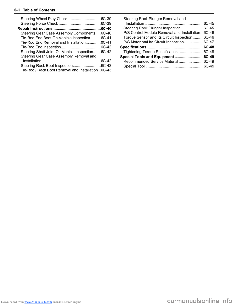
Steering Wheel Play Check ..............................6C-39
Steering Force Check .......................................6C-39
Repair Instructions ........... .................................6C-40
Steering Gear Case Assembly Components ....6C-40
Tie-Rod End Boot On-Vehic le Inspection .........6C-41
Tie-Rod End Removal and Installation..............6C-41
Tie-Rod End Inspection.....................................6C-42
Steering Shaft Joint On-Vehicle Inspection.......6C-42
Steering Gear Case Assembly Removal and Installation .......................................................6C-42
Steering Rack Boot Inspec tion ..........................6C-43
Tie-Rod / Rack Boot Removal and Installation ..6C-43 Steering Rack Plunger Removal and
Installation .......................................................6C-45
Steering Rack Plunger Inspection .....................6C-45
P/S Control Module Removal and Installation...6C-46
Torque Sensor and Its Circuit Inspection ..........6C-46
P/S Motor and Its Circuit Inspection ..................6C-47
Specifications ..................... ................................6C-48
Tightening Torque Specifications ......................6C-48
Special Tools and Equipmen t ...........................6C-49
Recommended Service Material .......................6C-49
Special Tool ......................................................6C-49
Page 871 of 1496

Downloaded from www.Manualslib.com manuals search engine Steering General Diagnosis: 6A-2
Diagnostic Information and Procedures
Steering Symptom DiagnosisS7RS0B6104001
ConditionPossible cause Correction / Reference Item
Hard steering Tire not adequately inflated Inflate tires to proper pressure.
Malfunction of power steering system Check and correct.
Bind in tie-rod end ball studs or lower
ball joints Replace tie-rod end or front suspension arm.
Disturbed front wheel alignment Check and adjust front wheel alignment.
Bind in steering column Repair or replace steering column.
Rack and pinion adjustment Check and adjustment rack and pinion torque.
Too much play in steering Wheel bearings worn Replace wheel bearing.
Loose steering gear case bolts Tighten gear case bolts.
Faulty steering gear case assembly Replace steering gear case assembly.
Worn steering shaft joints Replace joint.
Worn tie-rod ends or tie-rod inside ball
joints Replace tie-rod end or tie-rod.
Worn lower ball joints Replace front suspension control arm.
Rack and pinion adjustment Check and adjustment rack and pinion torque.
Poor return ability Bind in tie-rod end ball studs Replace tie-rod end.
Bind in ball joints Replace front suspension control arm.
Bind in steering column Repair or replace steering column.
Disturbed front end alignment Check and adjust front end alignment.
Faulty steering gear case assembly Replace steering gear case assembly.
Tires not adequately inflated Adjust tire pressure.
Rack and pinion adjustment Check and adjustment rack and pinion torque.
Rack and pinion noise
(Rattle or chuckle) Loose steering gear case bolts
Tighten steering gear case bolts.
Rack and pinion adjustment Check and adjustment rack and pinion torque.
Faulty steering gear case assembly Replace steering gear case assembly.
Broken or other wise damaged wheel
bearing(s) Replace wheel bearing(s).
Wander or poor steering
stability Mismatched or uneven tires
Replace or inflate tires to proper pressure.
Loosen ball joints and tie-rod ends Replace suspension control arm or tie-rod end.
Faulty struts or mountings Replace strut or repair mounting.
Loose stabilizer bar Tighten or replace stabilizer bar or bush.
Broken or sagging springs Replace spring.
Rack and pinion adjustment Check and adjustment rack and pinion torque.
Disturbed front wheel alignment Check and adjust front wheel alignment.
Faulty steering gear case assembly Replace steering gear case assembly.
Erratic steering when
braking Worn wheel bearing(s)
Replace wheel bearing(s).
Broken or sagging spring(s) Replace coil spring(s).
Wheel tires are inflated unequally Inflate tires to proper pressure.
Disturbed front wheel alignment Check and adjust front wheel alignment.
Brakes not working in unison Check and repair brake system.
Leaking caliper Repair or replace caliper.
Warped discs Replace brake disc.
Badly worn brake pads Replace brake pads.
Page 883 of 1496

Downloaded from www.Manualslib.com manuals search engine Power Assisted Steering System: 6C-1
Steeri ng
Power Assisted Steering System
Precautions
Steering System NoteS7RS0B6300001
NOTE
All steering gear fasteners are important attaching parts in that they could affect the performance of
vital parts and systems, and/or could result in major repair expense. They must be replaced with one of
the same part number or with an equivalent part if replacement becomes necessary. Do not use a
replacement part of lesser quality or substitute design. Torque values must be used as specified
during reassembly to assure proper retention of these parts.
Precautions in Diagnosing TroublesS7RS0B6300002
• Take a note of DTC indicated on the SUZUKI scan tool.
• Before inspection, be sure to read “Pre cautions for Electrical Circuit Service in Section 00” and understand what is
written there.
• DTC C1122 (engine speed signal failure) is indicated when ignition switch is at ON position and engine is not
running, but it means there is nothing abnormal if indica tion changes to a normal one when engine is started.
• As DTC is stored in memory of the P/S control module, be sure to clear memory after repair by performing the
procedure described in “DTC Clearance”.
Page 900 of 1496
Downloaded from www.Manualslib.com manuals search engine 6C-18 Power Assisted Steering System:
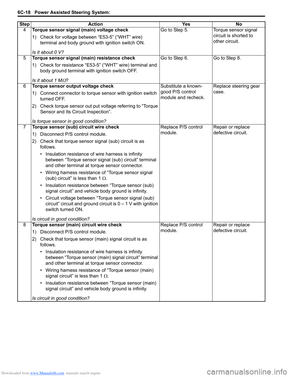
4Torque sensor signal (main) voltage check
1) Check for voltage between “E53-5” (“WHT” wire)
terminal and body ground with ignition switch ON.
Is it about 0 V? Go to Step 5. Torque sensor signal
circuit is shorted to
other circuit.
5 Torque sensor signal (main) resistance check
1) Check for resistance “E53-5” (“WHT” wire) terminal and
body ground terminal with ignition switch OFF.
Is it about 1 M
Ω? Go to Step 6. Go to Step 8.
6 Torque sensor output voltage check
1) Connect connector to torque sensor with ignition switch
turned OFF.
2) Check torque sensor out put voltage referring to “Torque Sensor and Its Circuit Inspection”.
Is torque sensor in good condition? Substitute a known-
good P/S control
module and recheck.
Replace steering gear
case.
7 Torque sensor (sub) circuit wire check
1) Disconnect P/S control module.
2) Check that torque sensor signal (sub) circuit is as
follows.
• Insulation resistance of wire harness is infinity between “Torque sensor signal (sub) circuit” terminal
and other terminal at torque sensor connector.
• Wiring harness resistance of “Torque sensor signal (sub) circuit” is less than 1 Ω.
• Insulation resistance between “Torque sensor (sub) signal circuit” and vehicle body ground is infinity.
• Circuit voltage between “Torque sensor signal (sub) circuit” circuit and ground circuit is 0 – 1 V with ignition
switch turned ON.
Is circuit in good condition? Replace P/S control
module.
Repair or replace
defective circuit.
8 Torque sensor (main) circuit wire check
1) Disconnect P/S control module.
2) Check that torque sensor (main) signal circuit is as
follows.
• Insulation resistance of wire harness is infinity between “Torque sensor (main) signal circuit” terminal
and other terminal at torque sensor connector.
• Wiring harness resistance of “Torque sensor (main) signal circuit” is less than 1 Ω.
• Insulation resistance between “Torque sensor (main) signal circuit” and vehicle body ground is infinity.
Is circuit in good condition? Replace P/S control
module.
Repair or replace
defective circuit.
Step Action Yes No
Page 902 of 1496
Downloaded from www.Manualslib.com manuals search engine 6C-20 Power Assisted Steering System:
DTC TroubleshootingStep Action Yes No 1 Was “EPS System Check” performed? Go to Step 2. Go to “EPS System
Check”.
2 DTC check
Is DTC C1153 and/or DTC C1155 indicated together? Go to applicable DTC
diag. flow.
Go to Step 3.
3 Torque sensor 5 V reference power supply circuit
voltage check
1) With ignition switch turned OFF, disconnect torque
sensor connector and check for proper terminal
connection to torque sensor connector.
2) If connections are OK, check for voltage between “E53- 6” (“RED” wire) terminal and body ground with ignition
switch ON.
Is it approx. 5 V? Go to Step 4. Go to Step 5.
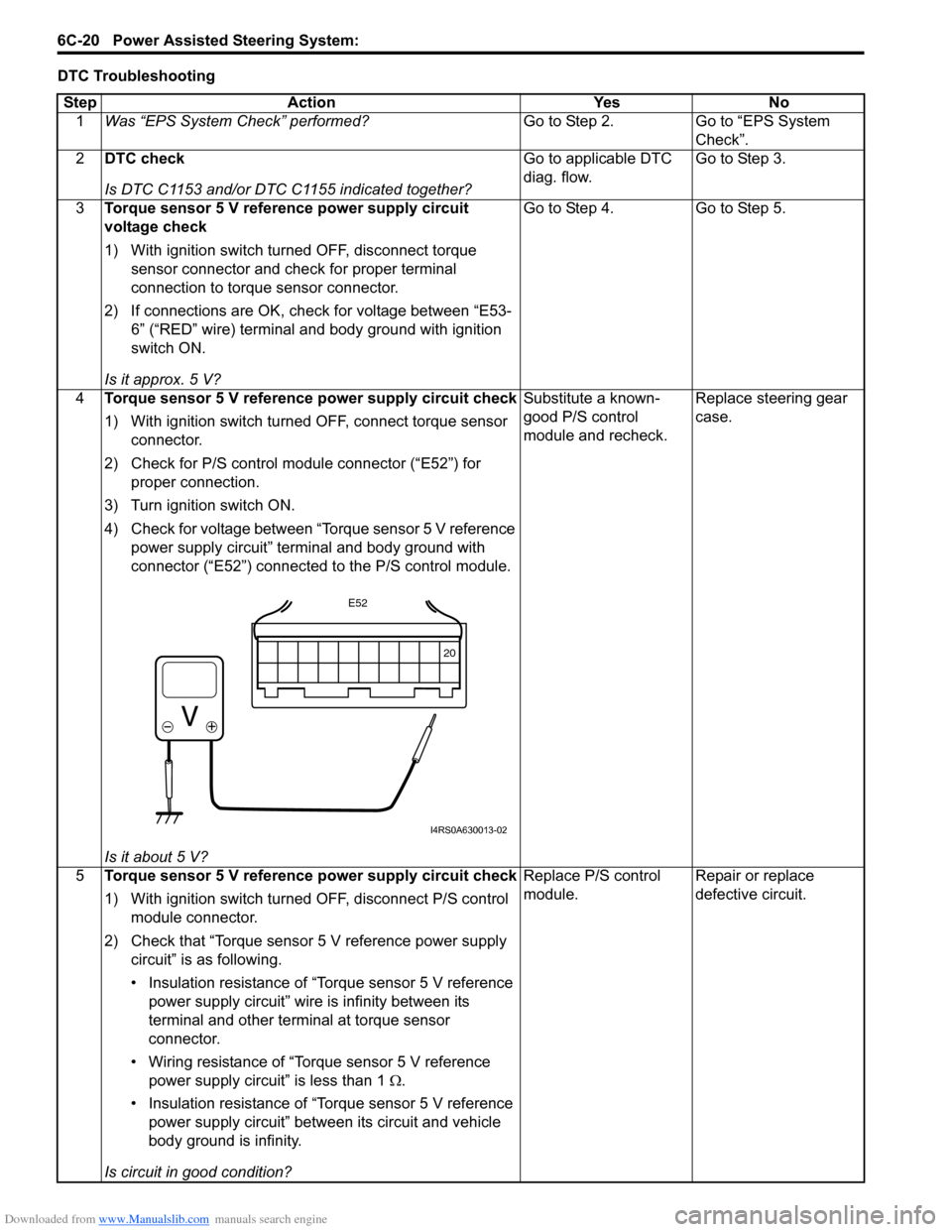
4 Torque sensor 5 V reference power supply circuit check
1) With ignition switch turned OFF, connect torque sensor
connector.
2) Check for P/S control module connector (“E52”) for proper connection.
3) Turn ignition switch ON.
4) Check for voltage between “Torque sensor 5 V reference power supply circuit” terminal and body ground with
connector (“E52”) connected to the P/S control module.
Is it about 5 V? Substitute a known-
good P/S control
module and recheck.
Replace steering gear
case.
5 Torque sensor 5 V reference power supply circuit check
1) With ignition switch turned OFF, disconnect P/S control
module connector.
2) Check that “Torque sensor 5 V reference power supply circuit” is as following.
• Insulation resistance of “Torque sensor 5 V reference power supply circuit” wire is infinity between its
terminal and other terminal at torque sensor
connector.
• Wiring resistance of “Torque sensor 5 V reference power supply circuit” is less than 1 Ω.
• Insulation resistance of “Torque sensor 5 V reference power supply circuit” between its circuit and vehicle
body ground is infinity.
Is circuit in good condition? Replace P/S control
module.
Repair or replace
defective circuit.
20
E52
I4RS0A630013-02
Page 904 of 1496
Downloaded from www.Manualslib.com manuals search engine 6C-22 Power Assisted Steering System:
DTC Troubleshooting
DTC C1118: Steering Torque Sensor Failure Signal Circuit HighS7RS0B6304015
Wiring Diagram
Refer to “DTC C1117: Steering Torque Sensor Failure Signal Circuit Low”.
DTC Detecting Condition and Trouble AreaStep Action Yes No
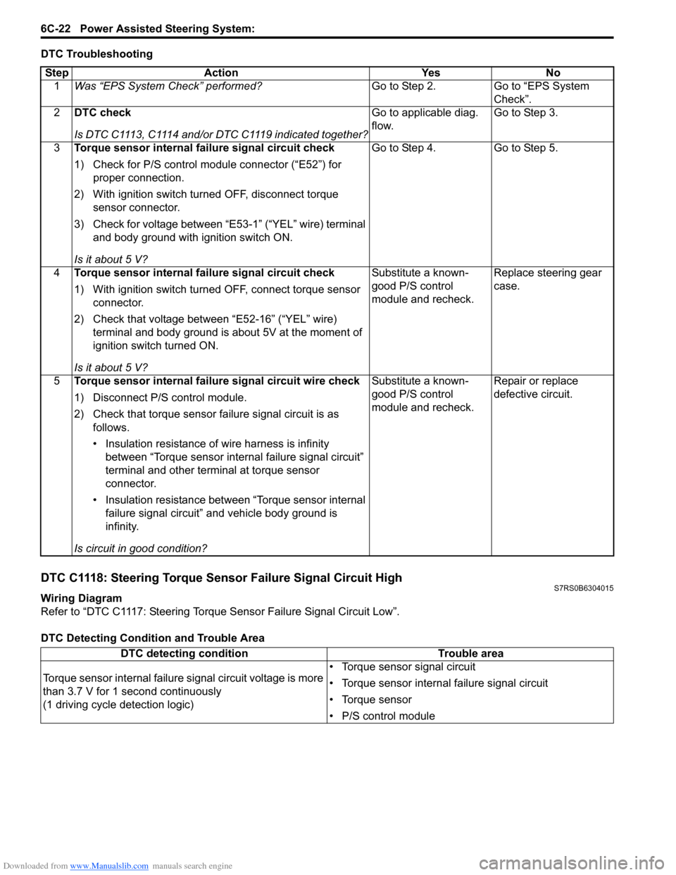
1 Was “EPS System Check” performed? Go to Step 2. Go to “EPS System
Check”.
2 DTC check
Is DTC C1113, C1114 and/or DTC C1119 indicated together? Go to applicable diag.
flow.
Go to Step 3.
3 Torque sensor internal failure signal circuit check
1) Check for P/S control module connector (“E52”) for
proper connection.
2) With ignition switch turned OFF, disconnect torque sensor connector.
3) Check for voltage between “E53-1” (“YEL” wire) terminal and body ground with ignition switch ON.
Is it about 5 V? Go to Step 4. Go to Step 5.
4 Torque sensor internal failure signal circuit check
1) With ignition switch turned OFF, connect torque sensor
connector.
2) Check that voltage between “E52-16” (“YEL” wire) terminal and body ground is about 5V at the moment of
ignition switch turned ON.
Is it about 5 V? Substitute a known-
good P/S control
module and recheck.
Replace steering gear
case.
5 Torque sensor internal failure signal circuit wire check
1) Disconnect P/S control module.
2) Check that torque sensor failure signal circuit is as
follows.
• Insulation resistance of wire harness is infinity between “Torque sensor internal failure signal circuit”
terminal and other terminal at torque sensor
connector.
• Insulation resistance between “Torque sensor internal failure signal circuit” and vehicle body ground is
infinity.
Is circuit in good condition? Substitute a known-
good P/S control
module and recheck.
Repair or replace
defective circuit.
DTC detecting condition
Trouble area
Torque sensor internal failure signal circuit voltage is more
than 3.7 V for 1 second continuously
(1 driving cycle detection logic) • Torque sensor signal circuit
• Torque sensor internal failure signal circuit
• Torque sensor
• P/S control module
Page 905 of 1496
Downloaded from www.Manualslib.com manuals search engine Power Assisted Steering System: 6C-23
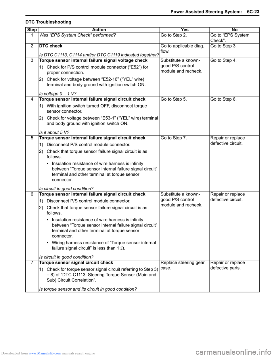
DTC TroubleshootingStep Action Yes No 1 Was “EPS System Check” performed? Go to Step 2. Go to “EPS System
Check”.
2 DTC check
Is DTC C1113, C1114 and/or DTC C1119 indicated together? Go to applicable diag.
flow.
Go to Step 3.
3 Torque sensor internal failure signal voltage check
1) Check for P/S control module connector (“E52”) for
proper connection.
2) Check for voltage between “E52-16” (“YEL” wire) terminal and body ground with ignition switch ON.
Is voltage 0 – 1 V? Substitute a known-
good P/S control
module and recheck.
Go to Step 4.
4 Torque sensor internal failure signal circuit check
1) With ignition switch turned OFF, disconnect torque
sensor connector.
2) Check for voltage between “E53-1” (“YEL” wire) terminal and body ground with ignition switch ON.
Is it about 5 V? Go to Step 5. Go to Step 6.
5 Torque sensor internal failure signal circuit check
1) Disconnect P/S control module connector.
2) Check that torque sensor failure signal circuit is as
follows.
• Insulation resistance of wire harness is infinity between “Torque sensor internal failure signal circuit”
terminal and other terminal at torque sensor
connector.
Is circuit in good condition? Go to Step 7. Repair or replace
defective circuit.
6 Torque sensor internal failure signal circuit check
1) Disconnect P/S control module connector.
2) Check that torque sensor failure signal circuit is as
follows.
• Insulation resistance of wire harness is infinity between “Torque sensor internal failure signal circuit”
terminal and other terminal at torque sensor
connector.
• Wiring harness resistance of “Torque sensor internal failure signal circuit” is less than 1 Ω.
Is circuit in good condition? Substitute a known-
good P/S control
module and recheck.
Repair or replace
defective circuit.
7 Torque sensor signal circuit check
1) Check for torque sensor signal circuit referring to Step 3)
– 8) of “DTC C1113: Steering Torque Sensor (Main and
Sub) Circuit Correlation”.
Is torque sensor and its circuit in good condition? Replace steering gear
case.
Repair or replace
defective parts.
Page 907 of 1496
Downloaded from www.Manualslib.com manuals search engine Power Assisted Steering System: 6C-25
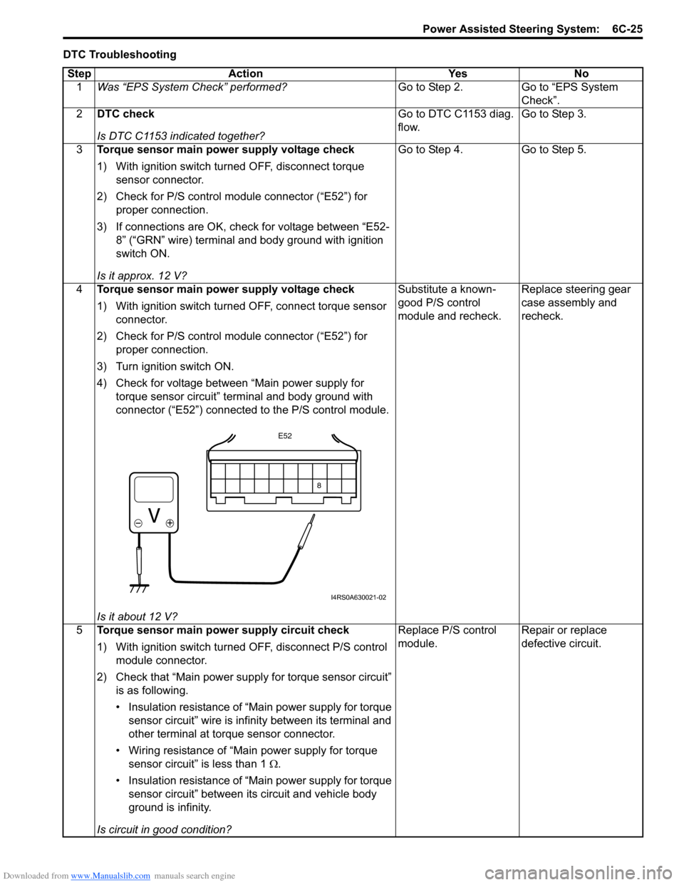
DTC TroubleshootingStep Action Yes No 1 Was “EPS System Check” performed? Go to Step 2. Go to “EPS System
Check”.
2 DTC check
Is DTC C1153 indicated together? Go to DTC C1153 diag.
flow.
Go to Step 3.
3 Torque sensor main power supply voltage check
1) With ignition switch turned OFF, disconnect torque
sensor connector.
2) Check for P/S control module connector (“E52”) for proper connection.
3) If connections are OK, check for voltage between “E52- 8” (“GRN” wire) terminal and body ground with ignition
switch ON.
Is it approx. 12 V? Go to Step 4. Go to Step 5.
4 Torque sensor main power supply voltage check
1) With ignition switch turned OFF, connect torque sensor
connector.
2) Check for P/S control module connector (“E52”) for proper connection.
3) Turn ignition switch ON.
4) Check for voltage between “Main power supply for torque sensor circuit” terminal and body ground with
connector (“E52”) connected to the P/S control module.
Is it about 12 V? Substitute a known-
good P/S control
module and recheck.
Replace steering gear
case assembly and
recheck.
5 Torque sensor main power supply circuit check
1) With ignition switch turned OFF, disconnect P/S control
module connector.
2) Check that “Main power supply for torque sensor circuit” is as following.
• Insulation resistance of “Main power supply for torque sensor circuit” wire is infinity between its terminal and
other terminal at torque sensor connector.
• Wiring resistance of “Main power supply for torque sensor circuit” is less than 1 Ω .
• Insulation resistance of “Main power supply for torque sensor circuit” between its circuit and vehicle body
ground is infinity.
Is circuit in good condition? Replace P/S control
module.
Repair or replace
defective circuit.
8
E52
I4RS0A630021-02