2005 SUZUKI SWIFT oil spec
[x] Cancel search: oil specPage 1162 of 1496
Downloaded from www.Manualslib.com manuals search engine 8B-124 Air Bag System:
21) Disconnect adapter cable (special tool) from air bag (inflator) module or seat belt pretensioner as soon as
possible. This will preven t adapter cable (special
tool) from damage due to possible contact with hot
air bag (inflator) module or hot seat belt
pretensioner.
22) Check adapter cable connector as follows. Adapter cable connector (special tool) is designed to
be reused. However it should be inspected for
damage after deployment and replaced if necessary.
23) With air bag (inflator) modules deployed and seat belt pretensioners acti vated, vehicle may be
scrapped in the same manner as non-air bag system
/ seat belt pretensioner equipped vehicle.
NOTE
Remaining steps are to be followed in the
unlikely event that air bag (inflator) module
did not deploy or seat belt pretensioner did
not activate.
24) Remove undeployed air bag (inflator) module(s) and/ or inactivated seat belt pretensioner(s) from vehicle.
For driver air bag (inflator) module, refer to “Driver
Air Bag (Inflator) Module Removal and Installation”.
For passenger air bag (inflator) module, refer to
“Passenger Air Bag (Inflator) Module Removal and
Installation”. For seat belt pretensioner, refer to
“Front Seat Belt Removal an d Installation in Section
8A”.
25) Temporarily store undeployed air bag (inflator) module referring to “Precautions on Service and
Diagnosis of Air Bag System” for details.
26) Contact your local distribu tor for further assistance.
Deployed Air Bag (Inflator) Module and
Activated Seat Belt Pretensioner Disposal
S7RS0B8206019
WARNING!
Failure to follow proper air bag (inflator)
module and seat belt pretensioner disposal
procedures can result in air bag deployment
and pretensioner activation which may cause
personal injury. The undeployed air bag
(inflator) module and the inactivated seat belt
pretensioner must not be disposed of
through normal refuse channels.
The undeployed air bag (inflator) module and
the inactivated seat belt pretensioner
contains substances that can cause severe
illness or personal injury if the sealed
container is damaged during disposal.
Deployed air bag (inflator) module and the activated seat
belt pretensioner can be disposed of through normal
refuse channels just like any other parts. For their
disposal, however, the following points should be noted.
• The air bag (inflator) module and the seat belt
pretensioner immediately after deployment / activation
is very hot. Wait for 30 minu tes to cool it off before
handling it.
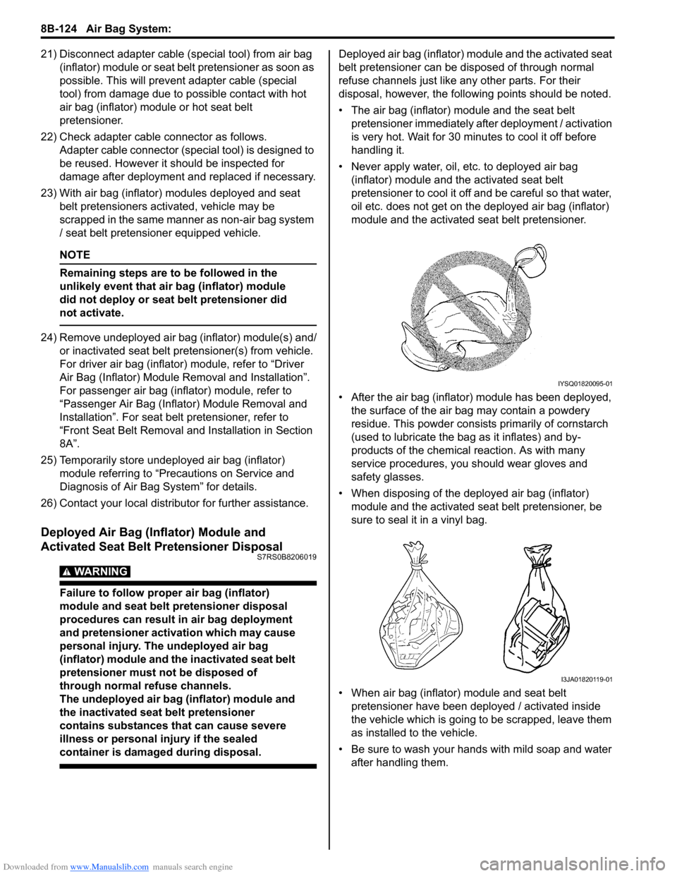
• Never apply water, oil, etc. to deployed air bag (inflator) module and the activated seat belt
pretensioner to cool it off and be careful so that water,
oil etc. does not get on the deployed air bag (inflator)
module and the activated seat belt pretensioner.
• After the air bag (inflator) module has been deployed, the surface of the air bag may contain a powdery
residue. This powder consists primarily of cornstarch
(used to lubricate the bag as it inflates) and by-
products of the chemical reaction. As with many
service procedures, you should wear gloves and
safety glasses.
• When disposing of the deployed air bag (inflator) module and the activated seat belt pretensioner, be
sure to seal it in a vinyl bag.
• When air bag (inflator) module and seat belt pretensioner have been deployed / activated inside
the vehicle which is going to be scrapped, leave them
as installed to the vehicle.
• Be sure to wash your hand s with mild soap and water
after handling them.
IYSQ01820095-01
I3JA01820119-01
Page 1164 of 1496
Downloaded from www.Manualslib.com manuals search engine 8B-126 Air Bag System:
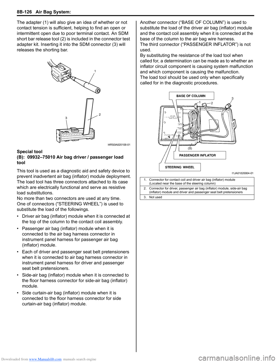
The adapter (1) will also give an idea of whether or not
contact tension is sufficient, helping to find an open or
intermittent open due to poor terminal contact. An SDM
short bar release tool (2) is included in the connector test
adapter kit. Inserting it in to the SDM connector (3) will
releases the shorting bar.
Special tool
(B): 09932–75010 Air bag driver / passenger load
tool
This tool is used as a diagno stic aid and safety device to
prevent inadvertent air bag (inflator) module deployment.
The load tool has three connectors attached to its case
which are electrically functional and serve as resistive
load substitutions.
No more than two connectors are used at any time.
One of connectors (“STEER ING WHEEL”) is used to
substitute the load of the followings.
• Driver air bag (inflator) module when it is connected at the top of the column to the contact coil assembly.
• Passenger air bag (inflator) module when it is connected to the air bag harness connector in
instrument panel harness for passenger air bag
(inflator) module.
• Each of driver and passen ger seat belt pretensioners
when it is connected to air bag harness connector in
instrument panel harness for driver and passenger
seat belt pretensioners.
• Side-air bag (inflator) module when it is connected to the floor harness connector for side-air bag (inflator)
module.
• Side curtain-air bag (inflator) module when it is connected to the floor harness connector for side
curtain-air bag (inflator) module. Another connec
tor (“BASE OF COLUMN ”) is used to
substitute the load of the driver air bag (inflator) module
and the contact coil assembly when it is connected at the
base of the column to the air bag wire harness.
The third connector (“PASSENGER INFLATOR”) is not
used.
By substituting the resistan ce of the load tool when
called for, a determination can be made as to whether an
inflator circuit component is causing system malfunction
and which component is causing the malfunction.
The load tool should be used only when specifically
called for in the diagnostic procedures.
1
2
3
I4RS0A820108-01
1. Connector for contact coil and driver air bag (inflator) module
(Located near the base of the steering column)
2. Connector for driver, passenger air bag (inflator) module, side-air bag (inflator) module and driver and passenger seat belt pretensioners
3. Not used
I1JA01820004-01
Page 1168 of 1496

Downloaded from www.Manualslib.com manuals search engine 9-ii Table of Contents
List of Connectors ........................................... 9A-103
C Connector .................................................... 9A-103
D Connector (M16A engine) ........................... 9A-104
E Connector .................................................... 9A-104
G Connector .................................................... 9A-106
J Connector ..................................................... 9A-108
K Connector .................................................... 9A-109
L Connector..................................................... 9A-109
M Connector (SPORT model) ......................... 9A-111
O Connector .................................................... 9A-111
R Connector .................................................... 9A-111
Lighting Systems .................................... 9B-1
Component Location ........... ................................9B-1
Lighting System Component s Location............... 9B-1
Interior Light System Location............................. 9B-2
Diagnostic Information and Procedures ............ 9B-2 Headlight Symptom Diagnosis ............................ 9B-2
Headlight Leveling System Symptom Diagnosis (If Equipped) ..................................... 9B-2
Turn Signal and Hazard Warning Light Symptom Diagnosis .......................................... 9B-3
Clearance, Tail and License Plate Light Symptom Diagnosis .......................................... 9B-3
Back-Up Light Symptom Diagnosis..................... 9B-4
Brake Light Symptom Diagnosis ......................... 9B-4
Front Fog Light Symptom Diagnosis (If Equipped) .......................................................... 9B-4
Interior Light Symptom Diagnosis ....................... 9B-5
Repair Instructions ..............................................9B-5 Headlight Housing Removal and Installation ...... 9B-5
Headlight Bulb Replacemen t............................... 9B-6
Headlight Aiming Adjustment with Screen .......... 9B-6
Headlight Switch (in Lighting Switch) Removal and Installation ................................... 9B-8
Headlight Switch (in Lighting Switch) Inspection .......................................................... 9B-8
Hazard Warning Switch Removal and Installation ......................................................... 9B-8
Hazard Warning Switch Inspection ..................... 9B-9
Brake Light Switch Inspection ............................. 9B-9
Turn Signal Light Switch (in Lighting Switch) Removal and Installation ................................... 9B-9
Turn Signal Light Switch (in Lighting Switch) Inspection .......................................................... 9B-9
Turn Signal and Hazard Warning Relay Removal and Installation ................................... 9B-9
Turn Signal and Hazard Warning Relay Inspection ........................................................ 9B-10
License Light Removal and Installation............. 9B-10
Front Fog Light Removal and Installation (If Equipped) ........................................................ 9B-11
Front Fog Light Bulb Replacement (If Equipped) ........................................................ 9B-11
Front Fog Light Switch Inspection (If Equipped) ........................................................ 9B-11
Front Fog Light Relay Inspection (If Equipped) ........................................................ 9B-11
Front Fog Light Aiming Adjustment with Screen (If Equipped) ....................................... 9B-12 Headlight Leveling Switch Inspection (If
Equipped) ........................................................ 9B-13
Headlight Leveling Actuator Inspection (If Equipped) ........................................................ 9B-13
Instrumentation / Driver Info. / Horn ...... 9C-1
Precautions ...........................................................9C-1 Precautions in Diagnosing Troubles for Combination Meter ............................................9C-1
General Description .............................................9C-1 CAN Communication System Description...........9C-1
Auto Volume Co ntrol System Description (If
Equipped) ..........................................................9C-3
Schematic and Routing Diagram ........................9C-4 Combination Meter Circuit Diagram ....................9C-4
Component Location ............ ...............................9C-6
Audio System Component Location ....................9C-6
Diagnostic Information and Procedures ............9C-6 Speedometer and VSS Symp tom Diagnosis ......9C-6
Tachometer Symptom Diagnosis ........................9C-6
Engine Coolant Temperature (ECT) Meter Symptom Diagnosis ..........................................9C-7
Fuel Meter Symptom Diagnosis ..........................9C-7
Low Fuel Warning Light Symptom Diagnosis .....9C-7
Oil Pressure Warning Light Symptom Diagnosis ..........................................................9C-8
Brake and Parking Brake Warning Light Symptom Diagnosis ..........................................9C-8
Seat Belt Reminder Light Symptom Diagnosis (If Equipped)......................................................9C-8
A/T Shift Position Indicator Symptom Diagnosis (A/T Model).......................................9C-9
Charge Warning Light Sy mptom Diagnosis ........9C-9
Main Beam (High Beam) Indicator Symptom Diagnosis ..........................................................9C-9
Warning Buzzer Circuit Sy mptom Diagnosis ....9C-10
Cigarette Lighter Symptom Diagnosis (If Equipped) ........................................................9C-10
Horn Symptom Diagnosis .................................9C-10
Information Display Symptom Diagnosis (If Equipped) ........................................................9C-11
Clock Symptom Diagnosis (If Equipped)...........9C-12
Audio System Symptom Diagnosis (If Equipped) ........................................................9C-12
Remote Audio Control Switch Symptom Diagnosis (If Equipped) ...................................9C-13
Navigation Symptom Diagnosis (If Equipped)...9C-14
Repair Instructions ............ ................................9C-14
Ignition Switch Removal and Installation...........9C-14
Ignition Switch Inspection..................................9C-14
Combination Meter Removal and Installation ...9C-15
Fuel Level Sensor Removal and Installation .....9C-15
Fuel Level Sensor Inspection ............................9C-15
Oil Pressure Switch Remova l and Installation ..9C-15
Oil Pressure Switch Inspec tion .........................9C-16
Engine Coolant Temperature (ECT) Sensor Inspection ........................................................9C-16
Brake Fluid Level Switch Inspection .................9C-16
Parking Brake Switch Inspec tion.......................9C-16
Page 1303 of 1496
Downloaded from www.Manualslib.com manuals search engine Instrumentation / Driver Info. / Horn: 9C-8
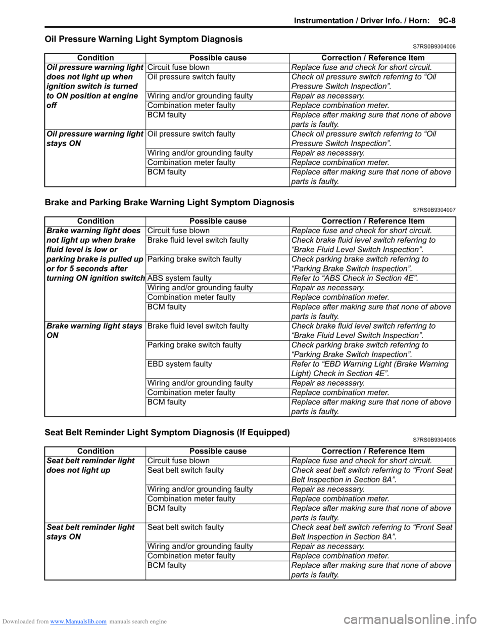
Oil Pressure Warning Light Symptom DiagnosisS7RS0B9304006
Brake and Parking Brake Warning Light Symptom DiagnosisS7RS0B9304007
Seat Belt Reminder Light Symptom Diagnosis (If Equipped)S7RS0B9304008
Condition Possible cause Correction / Reference Item
Oil pressure warning light
does not light up when
ignition switch is turned
to ON position at engine
off Circuit fuse blown
Replace fuse and check for short circuit.
Oil pressure switch faulty Check oil pressure switch referring to “Oil
Pressure Switch Inspection”.
Wiring and/or grounding faulty Repair as necessary.
Combination meter faulty Replace combination meter.
BCM faulty Replace after making sure that none of above
parts is faulty.
Oil pressure warning light
stays ON Oil pressure switch faulty
Check oil pressure switch referring to “Oil
Pressure Switch Inspection”.
Wiring and/or grounding faulty Repair as necessary.
Combination meter faulty Replace combination meter.
BCM faulty Replace after making sure that none of above
parts is faulty.
ConditionPossible cause Correction / Reference Item
Brake warning light does
not light up when brake
fluid level is low or
parking brake is pulled up
or for 5 seconds after
turning ON ignition switch Circuit fuse blown
Replace fuse and check for short circuit.
Brake fluid level switch faulty Check brake fluid level switch referring to
“Brake Fluid Level Switch Inspection”.
Parking brake switch faulty Check parking brake switch referring to
“Parking Brake Switch Inspection”.
ABS system faulty Refer to “ABS Check in Section 4E”.
Wiring and/or grounding faulty Repair as necessary.
Combination meter faulty Replace combination meter.
BCM faulty Replace after making sure that none of above
parts is faulty.
Brake warning light stays
ON Brake fluid level switch faulty
Check brake fluid level switch referring to
“Brake Fluid Level Switch Inspection”.
Parking brake switch faulty Check parking brake switch referring to
“Parking Brake Switch Inspection”.
EBD system faulty Refer to “EBD Warning Light (Brake Warning
Light) Check in Section 4E”.
Wiring and/or grounding faulty Repair as necessary.
Combination meter faulty Replace combination meter.
BCM faulty Replace after making sure that none of above
parts is faulty.
ConditionPossible cause Correction / Reference Item
Seat belt reminder light
does not light up Circuit fuse blown
Replace fuse and check for short circuit.
Seat belt switch faulty Check seat belt switch referring to “Front Seat
Belt Inspection in Section 8A”.
Wiring and/or grounding faulty Repair as necessary.
Combination meter faulty Replace combination meter.
BCM faulty Replace after making sure that none of above
parts is faulty.
Seat belt reminder light
stays ON Seat belt switch faulty
Check seat belt switch referring to “Front Seat
Belt Inspection in Section 8A”.
Wiring and/or grounding faulty Repair as necessary.
Combination meter faulty Replace combination meter.
BCM faulty Replace after making sure that none of above
parts is faulty.
Page 1308 of 1496
Downloaded from www.Manualslib.com manuals search engine 9C-13 Instrumentation / Driver Info. / Horn:
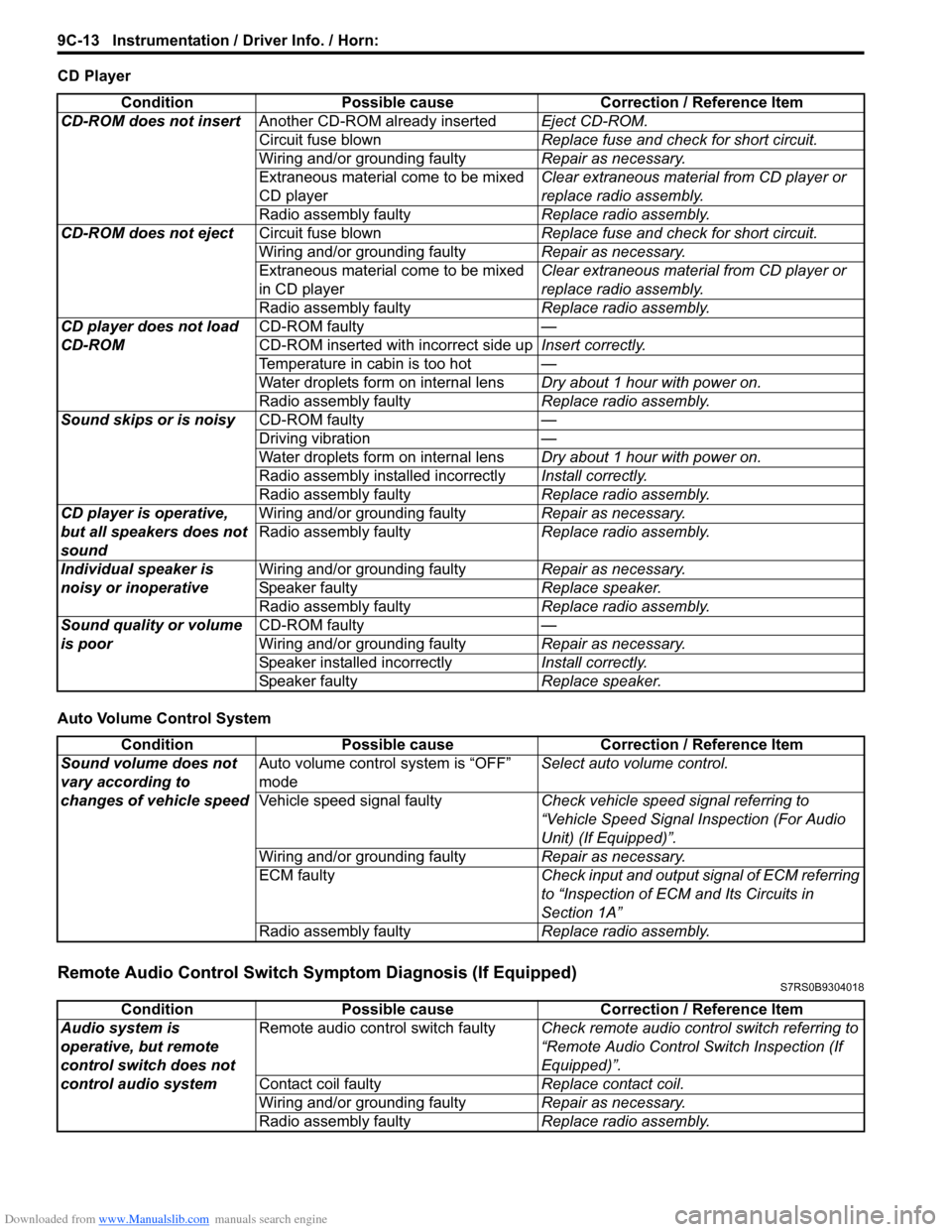
CD Player
Auto Volume Control System
Remote Audio Control Switch Symptom Diagnosis (If Equipped)S7RS0B9304018
ConditionPossible cause Correction / Reference Item
CD-ROM does not insert Another CD-ROM already inserted Eject CD-ROM.
Circuit fuse blown Replace fuse and check for short circuit.
Wiring and/or grounding faulty Repair as necessary.
Extraneous material come to be mixed
CD player Clear extraneous material from CD player or
replace radio assembly.
Radio assembly faulty Replace radio assembly.
CD-ROM does not eject Circuit fuse blown Replace fuse and check for short circuit.
Wiring and/or grounding faulty Repair as necessary.
Extraneous material come to be mixed
in CD player Clear extraneous material from CD player or
replace radio assembly.
Radio assembly faulty Replace radio assembly.
CD player does not load
CD-ROM CD-ROM faulty
—
CD-ROM inserted wit h incorrect side upInsert correctly.
Temperature in cabin is too hot —
Water droplets form on internal lens Dry about 1 hour with power on.
Radio assembly faulty Replace radio assembly.
Sound skips or is noisy CD-ROM faulty —
Driving vibration —
Water droplets form on internal lens Dry about 1 hour with power on.
Radio assembly installed incorrectly Install correctly.
Radio assembly faulty Replace radio assembly.
CD player is operative,
but all speakers does not
sound Wiring and/or grounding faulty
Repair as necessary.
Radio assembly faulty Replace radio assembly.
Individual speaker is
noisy or inoperative Wiring and/or grounding faulty
Repair as necessary.
Speaker faulty Replace speaker.
Radio assembly faulty Replace radio assembly.
Sound quality or volume
is poor CD-ROM faulty
—
Wiring and/or grounding faulty Repair as necessary.
Speaker installed incorrectly Install correctly.
Speaker faulty Replace speaker.
ConditionPossible cause Correction / Reference Item
Sound volume does not
vary according to
changes of vehicle speed Auto volume control system is “OFF”
mode
Select auto volume control.
Vehicle speed signal faulty Check vehicle speed signal referring to
“Vehicle Speed Signal Inspection (For Audio
Unit) (If Equipped)”.
Wiring and/or grounding faulty Repair as necessary.
ECM faulty Check input and output signal of ECM referring
to “Inspection of ECM and Its Circuits in
Section 1A”
Radio assembly faulty Replace radio assembly.
ConditionPossible cause Correction / Reference Item
Audio system is
operative, but remote
control switch does not
control audio system Remote audio control switch faulty
Check remote audio control switch referring to
“Remote Audio Control Switch Inspection (If
Equipped)”.
Contact coil faulty Replace contact coil.
Wiring and/or grounding faulty Repair as necessary.
Radio assembly faulty Replace radio assembly.
Page 1310 of 1496
Downloaded from www.Manualslib.com manuals search engine 9C-15 Instrumentation / Driver Info. / Horn:
Combination Meter Removal and InstallationS7RS0B9306003
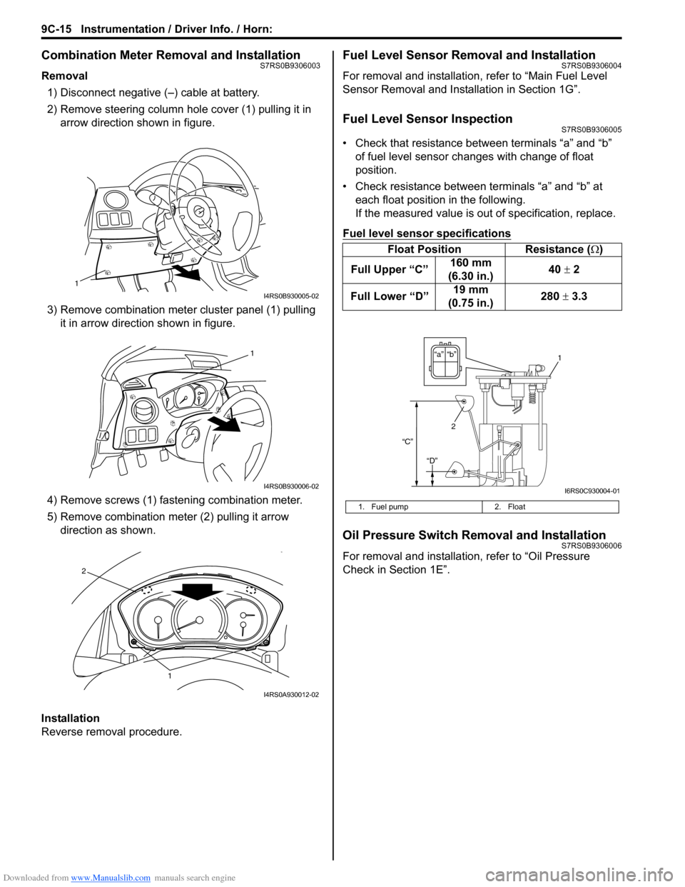
Removal1) Disconnect negative (–) cable at battery.
2) Remove steering column hole cover (1) pulling it in arrow direction shown in figure.
3) Remove combination mete r cluster panel (1) pulling
it in arrow direction shown in figure.
4) Remove screws (1) fast ening combination meter.
5) Remove combination me ter (2) pulling it arrow
direction as shown.
Installation
Reverse removal procedure.
Fuel Level Sensor Removal and InstallationS7RS0B9306004
For removal and installation, refer to “Main Fuel Level
Sensor Removal and Installation in Section 1G”.
Fuel Level Sensor InspectionS7RS0B9306005
• Check that resistance between terminals “a” and “b” of fuel level sensor changes with change of float
position.
• Check resistance between terminals “a” and “b” at each float position in the following.
If the measured value is out of specification, replace.
Fuel level sensor specifications
Oil Pressure Switch Removal and InstallationS7RS0B9306006
For removal and installation , refer to “Oil Pressure
Check in Section 1E”.
1
I4RS0B930005-02
1
I4RS0B930006-02
1
2
I4RS0A930012-02
Float Position Resistance (Ω)
Full Upper “C” 160 mm
(6.30 in.) 40
± 2
Full Lower “D” 19 mm
(0.75 in.) 280
± 3.3
1. Fuel pump 2. Float
“b”“a”
2
“C”
“D”
1
I6RS0C930004-01
Page 1311 of 1496
Downloaded from www.Manualslib.com manuals search engine Instrumentation / Driver Info. / Horn: 9C-16
Oil Pressure Switch InspectionS7RS0B9306007
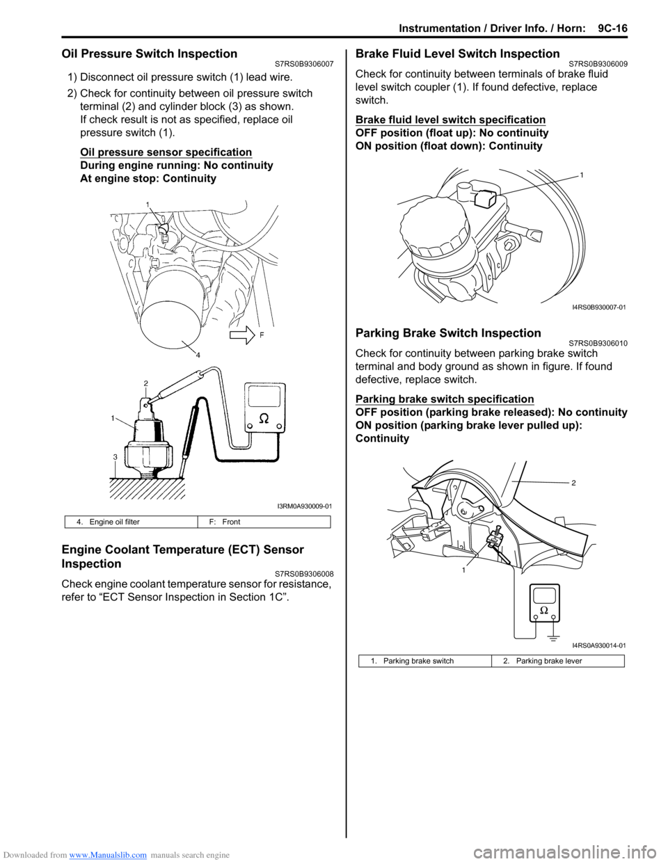
1) Disconnect oil pressure switch (1) lead wire.
2) Check for continuity between oil pressure switch terminal (2) and cylinder block (3) as shown.
If check result is not as specified, replace oil
pressure switch (1).
Oil pressure sensor specification
During engine running: No continuity
At engine stop: Continuity
Engine Coolant Temperature (ECT) Sensor
Inspection
S7RS0B9306008
Check engine coolant temperat ure sensor for resistance,
refer to “ECT Sensor Inspection in Section 1C”.
Brake Fluid Level Switch InspectionS7RS0B9306009
Check for continuity between terminals of brake fluid
level switch coupler (1). If found defective, replace
switch.
Brake fluid level switch specification
OFF position (float up): No continuity
ON position (float down): Continuity
Parking Brake Switch InspectionS7RS0B9306010
Check for continuity between parking brake switch
terminal and body ground as shown in figure. If found
defective, replace switch.
Parking brake switch specification
OFF position (parking brake released): No continuity
ON position (parking brake lever pulled up):
Continuity
4. Engine oil filter F: Front
I3RM0A930009-01
1. Parking brake switch 2. Parking brake lever
1
I4RS0B930007-01
12
I4RS0A930014-01
Page 1317 of 1496
Downloaded from www.Manualslib.com manuals search engine Instrumentation / Driver Info. / Horn: 9C-22
Remote Audio Control Switch Inspection (If
Equipped)
S7RS0B9306024
1) Remove driver air bag (inflator) module referring to
“Driver Air Bag (Inflator) Module Removal and
Installation in Section 8B”.
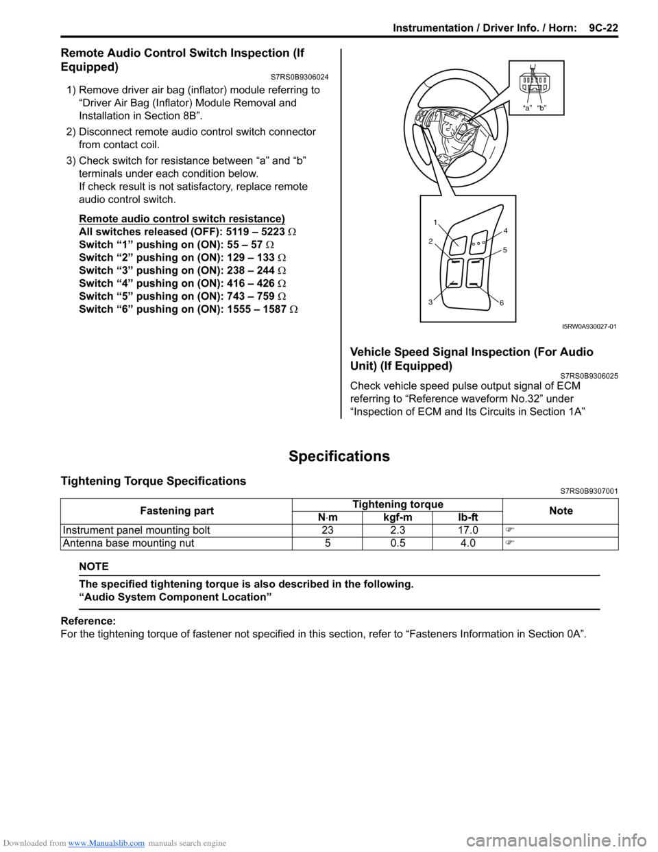
2) Disconnect remote audio control switch connector
from contact coil.
3) Check switch for resistance between “a” and “b” terminals under each condition below.
If check result is not satisfactory, replace remote
audio control switch.
Remote audio control switch resistance)
All switches released (OFF): 5119 – 5223 Ω
Switch “1” pushing on (ON): 55 – 57 Ω
Switch “2” pushing on (ON): 129 – 133 Ω
Switch “3” pushing on (ON): 238 – 244 Ω
Switch “4” pushing on (ON): 416 – 426 Ω
Switch “5” pushing on (ON): 743 – 759 Ω
Switch “6” pushing on (ON): 1555 – 1587 Ω
Vehicle Speed Signal Inspection (For Audio
Unit) (If Equipped)
S7RS0B9306025
Check vehicle speed pulse output signal of ECM
referring to “Reference waveform No.32” under
“Inspection of ECM and Its Circuits in Section 1A”
Specifications
Tightening Torque SpecificationsS7RS0B9307001
NOTE
The specified tightening torque is also described in the following.
“Audio System Component Location”
Reference:
For the tightening torque of fastener not specified in this section, refer to “Fasteners Information in Section 0A”.
“b”“a”
1
2
3 4
5
6
I5RW0A930027-01
Fastening part Tightening torque
Note
N ⋅mkgf-mlb-ft
Instrument panel mounting bolt 23 2.3 17.0 �)
Antenna base mounting nut 5 0.5 4.0 �)