2005 SUZUKI SWIFT Engine general information
[x] Cancel search: Engine general informationPage 468 of 1496

Downloaded from www.Manualslib.com manuals search engine 2D-1 Wheels and Tires:
Suspension
Wheels and Tires
Precautions
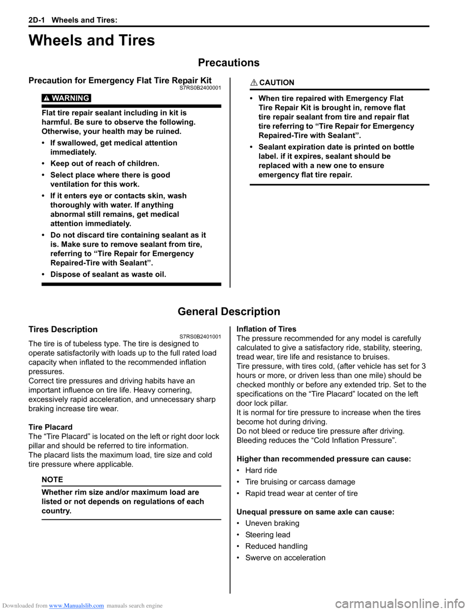
Precaution for Emergency Flat Tire Repair KitS7RS0B2400001
WARNING!
Flat tire repair sealant including in kit is
harmful. Be sure to observe the following.
Otherwise, your health may be ruined.
• If swallowed, get medical attention immediately.
• Keep out of reach of children.
• Select place where there is good ventilation for this work.
• If it enters eye or contacts skin, wash thoroughly with water. If anything
abnormal still rema ins, get medical
attention immediately.
• Do not discard tire containing sealant as it is. Make sure to remove sealant from tire,
referring to “Tire Repair for Emergency
Repaired-Tire with Sealant”.
• Dispose of sealant as waste oil.
CAUTION!
• When tire repaired with Emergency Flat Tire Repair Kit is brought in, remove flat
tire repair sealant from tire and repair flat
tire referring to “Tire Repair for Emergency
Repaired-Tire with Sealant”.
• Sealant expiration date is printed on bottle label. if it expires, sealant should be
replaced with a new one to ensure
emergency flat tire repair.
General Description
Tires DescriptionS7RS0B2401001
The tire is of tubeless type. The tire is designed to
operate satisfactorily with loads up to the full rated load
capacity when inflated to the recommended inflation
pressures.
Correct tire pressures and driving habits have an
important influence on tire life. Heavy cornering,
excessively rapid acceleration, and unnecessary sharp
braking increase tire wear.
Tire Placard
The “Tire Placard” is located on the left or right door lock
pillar and should be referred to tire information.
The placard lists the maximum load, tire size and cold
tire pressure where applicable.
NOTE
Whether rim size and/or maximum load are
listed or not depends on regulations of each
country.
Inflation of Tires
The pressure recommended for any model is carefully
calculated to give a satisfacto ry ride, stability, steering,
tread wear, tire life and resistance to bruises.
Tire pressure, with tires cold, (after vehicle has set for 3
hours or more, or driven less than one mile) should be
checked monthly or before any extended trip. Set to the
specifications on the “Tire Placard” located on the left
door lock pillar.
It is normal for tire pressure to increase when the tires
become hot during driving.
Do not bleed or reduce tire pressure after driving.
Bleeding reduces the “Cold Inflation Pressure”.
Higher than recommended pressure can cause:
• Hard ride
• Tire bruising or carcass damage
• Rapid tread wear at center of tire
Unequal pressure on same axle can cause:
• Uneven braking
• Steering lead
• Reduced handling
• Swerve on acceleration
Page 477 of 1496

Downloaded from www.Manualslib.com manuals search engine Table of Contents 3- i
3
Section 3
CONTENTS
Driveline / Axle
Precautions ................................................. 3-1
Precautions............................................................. 3-1
Precautions for Driveline / Axle ............................. 3-1
Drive Shaft / Axle .......... ........................... 3A-1
General Description ............................................. 3A-1
Front Drive Shaft Construction ............................ 3A-1
Component Locatio n ........................................... 3A-1
Front Drive Shaft Assembly Components Location ............................................................ 3A-1
Diagnostic Information and Procedures ............ 3A-2 Front Drive Shaft Symptom Diagnosis ................ 3A-2
Repair Instructions .............................................. 3A-3 Front Drive Shaft Components ........................... 3A-3 Front Drive Shaft Assembly On-Vehicle
Inspection .......................................................... 3A-4
Front Drive Shaft Assembly Removal and Installation ......................................................... 3A-4
Front Drive Shaft Disassembly and Reassembly ...................................................... 3A-6
Center Shaft and Center Bearing Support Disassembly and Reassembly ........................ 3A-14
Specifications .................... .................................3A-15
Tightening Torque Specifications ...................... 3A-15
Special Tools and Equipmen t ...........................3A-15
Recommended Service Material ....................... 3A-15
Special Tool ...................................................... 3A-15
Page 495 of 1496

Downloaded from www.Manualslib.com manuals search engine Table of Contents 4- i
4
Section 4
CONTENTS
Brakes
Precautions ................................................. 4-1
Precautions............................................................. 4-1
Precautions for Brakes .......................................... 4-1
Brake Control System and Diagnosis ... 4A-1
Precautions........................................................... 4A-1Precautions on Brake .......................................... 4A-1
General Description ............................................. 4A-1 Brakes Construction ............................................ 4A-1
Brake Pedal Foot Protection System Construction ...................................................... 4A-2
Front Brake Hose / Pipe Co nstruction................. 4A-3
Rear Brake Hose / Pipe Construction ................. 4A-4
Diagnostic Information and Procedures ............ 4A-4 Brakes Diagnosis Note ....................................... 4A-4
Brakes Symptom Diagnosis ................................ 4A-5
Repair Instructions .............................................. 4A-7 Brake Pedal Components ................................... 4A-7
Brake Pedal Free Height Inspection ................... 4A-7
Brake Pedal Play Inspection ............................... 4A-7
Excessive Pedal Travel Inspection ..................... 4A-8
Brake Fluid Level Inspection ............................... 4A-8
Stop Light Switch Adjustment ............................. 4A-8
Air Bleeding of Brake System ............................. 4A-9
Front Brake Hose / Pipe Removal and Installation ....................................................... 4A-10
Rear Brake Hose / Pipe Removal and Installation ....................................................... 4A-10
Brake Hose and Pipe Inspection ....................... 4A-11
Master Cylinder Components............................ 4A-11
Master Cylinder Assembly Removal and Installation ....................................................... 4A-12
Master Cylinder Rese rvoir Removal and
Installation ....................................................... 4A-13
Master Cylinder Assemb ly Disassembly and
Assembly ........................................................ 4A-14
Master Cylinder Assembly Inspection ............... 4A-15
Brake Booster Components .............................. 4A-15
Booster Operation Inspection ........................... 4A-16
Brake Booster Removal and Installation ........... 4A-17
Brake Booster Inspection and Adjustment ........ 4A-18
Specifications ..................................................... 4A-18
Tightening Torque Specifications ...................... 4A-18
Special Tools and Equipmen t ........................... 4A-18 Recommended Service Material ....................... 4A-18
Front Brakes .......
..................................... 4B-1
Repair Instructions ........... ...................................4B-1
Front Disc Brake Components ............................ 4B-1
Front Disc Brake Pad On-Vehicle Inspection ...... 4B-2
Front Disc Brake Pad Removal and Installation ......................................................... 4B-2
Front Disc Brake Pad Inspection......................... 4B-3
Front Disc Brake Ca liper Removal and
Installation ......................................................... 4B-3
Front Disc Brake Caliper Disassembly and Assembly........................................................... 4B-4
Front Disc Brake Caliper In spection.................... 4B-6
Front Brake Disc Removal and Installation ......... 4B-6
Front Brake Disc Inspection ................................ 4B-7
Specifications .................... ...................................4B-8
Tightening Torque Specifications ........................ 4B-8
Special Tools and Equipmen t .............................4B-8
Recommended Service Material ......................... 4B-8
Special Tool ........................................................ 4B-8
Rear Brakes................... ........................... 4C-1
Repair Instructions ........... ...................................4C-1
Rear Disc Brake Components.............................4C-1
Rear Disc Brake Pad Removal and Installation .........................................................4C-2
Rear Disc Brake Caliper Removal and Installation .........................................................4C-3
Rear Disc Brake Pad Inspection .........................4C-6
Rear Disc Brake Caliper Disassembly and Assembly...........................................................4C-6
Rear Disc Brake Caliper Inspection ....................4C-8
Rear Flexible Hose Remova l and Installation .....4C-8
Rear Brake Disc Removal and Installation..........4C-9
Rear Brake Disc Inspection.................................4C-9
Specifications .................... .................................4C-10
Tightening Torque Specifications ......................4C-10
Special Tools and Equipmen t ...........................4C-11
Recommended Service Material .......................4C-11
Special Tool ......................................................4C-11
Parking Brake ................. ......................... 4D-1
General Description .............................................4D-1
Parking Brake Cable Construction ......................4D-1
Page 496 of 1496

Downloaded from www.Manualslib.com manuals search engine 4-ii Table of Contents
Repair Instructions ..............................................4D-2Parking Brake Inspection and Adjustment ..........4D-2
Parking Brake Cable Removal and Installation ......................................................... 4D-3
Parking Brake Lever Removal and Installation ....4D-3
Specifications .... ...................................................4D-4
Tightening Torque Specifications ........................4D-4
ABS ........................................... .................4E-1
Precautions........................................................... 4E-1
Precautions in Diagnosing Troubles ................... 4E-1
Precautions in On-Vehicle Service...................... 4E-1
Precautions in Hydraulic Unit Operation Check ................................................................ 4E-1
General Description ............................................. 4E-2 ABS Description .................................................. 4E-2
ABS Hydraulic Unit / Control Module Assembly Description ....................................... 4E-2
CAN Communication System Description........... 4E-3
Schematic and Routing Diagram ........................ 4E-4 ABS Schematic ................................................... 4E-4
ABS Wiring Circuit Diagram ................................ 4E-5
Component Location ........... ................................ 4E-7
ABS Components Location ................................. 4E-7
Front Wheel Speed Sensor Components Location ............................................................ 4E-7
Rear Wheel Speed Sensor Components Location ............................................................ 4E-8
Diagnostic Information and Procedures ............ 4E-8 ABS Check .......................................................... 4E-8
ABS Warning Light Check................................. 4E-10
EBD Warning Light (Brake Warning Light) Check .............................................................. 4E-10
DTC Check........................................................ 4E-11
DTC Table ......................................................... 4E-11
DTC Clearance ................................................. 4E-12
Scan Tool Data ................................................. 4E-12
ABS Warning Light Does Not Come ON at Ignition Switch ON .......................................... 4E-13
ABS Warning Light Comes ON Steady ............. 4E-14
EBD Warning Light (Brake Warning Light) Comes ON Steady .......................................... 4E-15
Serial Data Link Circuit Check .......................... 4E-16
DTC C1021, C1022 / C1025, C1026 / C1031, C1032 / C1035, C1036: Right-Front / Left-
Front / Right-Rear / Left-Rear Wheel Speed
Sensor Circuit or Sensor Ring ........................ 4E-18
DTC C1041 / C1045 / C1051 / C1055, DTC C1042 / C1046 / C1052 / C1056: Right-Front
/ Left-Front / Right-Rear / Left-Rear Inlet
Solenoid Circuit, Right-Front / Left-Front /
Right-Rear / Left-Rear Outlet Solenoid
Circuit .............................................................. 4E-20
DTC C1057: Power Source Circuit ................... 4E-21
DTC C1061: ABS Pump Motor and/or Motor Driver Circuit ................................................... 4E-22
DTC C1063: Solenoid Valve Power Supply Driver Circuit ................................................... 4E-23
DTC C1071: ABS Control Module..................... 4E-24 DTC U1073: Control Module Communication
Bus Off ............................................................ 4E-25
DTC U1100: Lost Communication with ECM (Reception Error)............................................. 4E-27
Repair Instructions ............ ................................ 4E-28
ABS Hydraulic Unit Operati on Check................ 4E-28
ABS Hydraulic Unit / Control Module
Assembly Components ...... ............................. 4E-29
ABS Hydraulic Unit / Control Module
Assembly On-Vehicle Inspection .................... 4E-29
ABS Hydraulic Unit / Control Module
Assembly Removal and Inst allation ................ 4E-29
Front / Rear Wheel Speed Sensor On-Vehicle Inspection ........................................................ 4E-31
Front Wheel Speed Sensor Removal and Installation ....................................................... 4E-32
Front Wheel Speed Sensor Inspection ............. 4E-32
Rear Wheel Speed Sensor Removal and Installation ....................................................... 4E-33
Rear Wheel Speed Sensor Inspection .............. 4E-34
Front Wheel Encoder On-Veh icle Inspection .... 4E-34
Front wheel Enco der Removal and
Installation ....................................................... 4E-34
Rear Wheel Encoder On-Veh icle Inspection..... 4E-34
Rear Wheel Encoder Removal and Installation ....................................................... 4E-34
Specifications ..................... ................................ 4E-35
Tightening Torque Specifications ...................... 4E-35
Special Tools and Equipmen t ........................... 4E-35
Special Tool ...................................................... 4E-35
Electronic Stability Prog ram ...................4F-1
Precautions ........................................................... 4F-1
Precautions in Diagnosing Troubles ................... 4F-1
Precautions in On-Vehicle Service...................... 4F-1
Precautions in Hydraulic Unit Operation Check ................................................................ 4F-1
Precautions in Sensor Calibration ....................... 4F-1
Precautions in Speedometer Test or Other Tests ................................................................. 4F-2
General Description ............................................. 4F-2 Electronic Stability Program Description ............. 4F-2
Electronic Stability Program Construction ........... 4F-3
ESP® Hydraulic Unit / Control Module
Assembly Description........................................ 4F-5
Warning Lamp, Indicator Lamp Description ........ 4F-6
CAN Communication System Description........... 4F-6
CAN Communication System For Electronic Stability Program Description ............................ 4F-7
Schematic and Routing Diagram ........................ 4F-8 Electronic Stability Program Schematic .............. 4F-8
Electronic Stability Program Wiring Circuit Diagram............................................................. 4F-9
Component Location ............ ............................. 4F-11
Electronic Stability Program Component
Location........................................................... 4F-11
Diagnostic Information and Procedures .......... 4F-12 Electronic Stability Program System Check ...... 4F-12
ESP® Warning lamp Check .............................. 4F-14
Page 498 of 1496

Downloaded from www.Manualslib.com manuals search engine 4-1 Precautions:
Brakes
Precautions
Precautions
Precautions for BrakesS7RS0B4000001
Suspension Caution
Refer to “Suspension Caution in Section 00”.
Wheels and Tires Caution
Refer to “Wheels and Tires Caution in Section 00”.
Brake Caution
Refer to “Brake Caution in Section 00”.
ESP® System Precautions
Refer to “Precaution for Vehicle Equipped with ESP ® System in Section 00”.
General Precautions
Refer to “General Precautions in Section 00”.
Vehicle Lifting Points
Refer to “Vehicle Liftin g Points in Section 0A”.
Fastener Caution
Refer to “Fastener Caution in Section 00”.
Fastener Information
Refer to “Fasteners Information in Section 0A”.
Page 576 of 1496

Downloaded from www.Manualslib.com manuals search engine 4F-2 Electronic Stability Program:
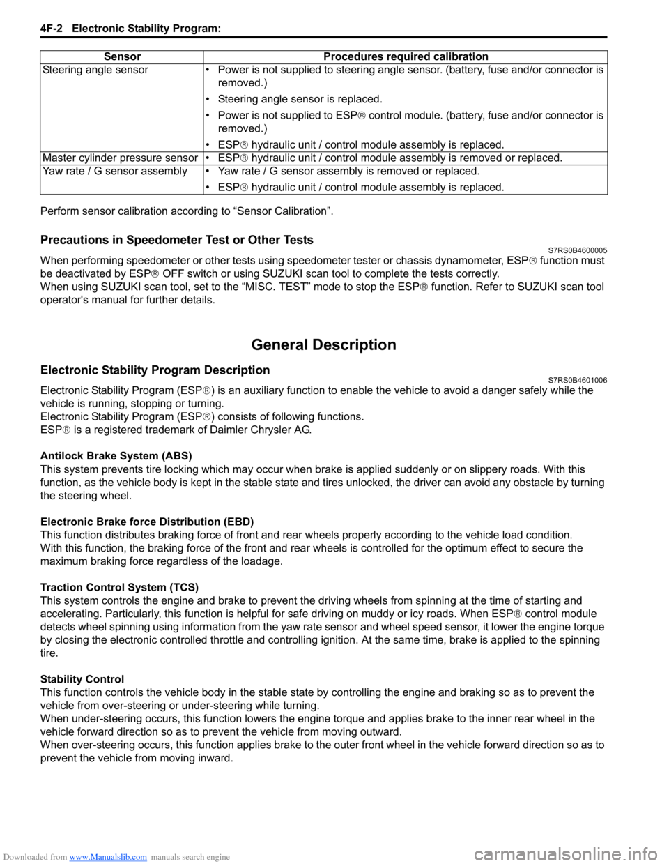
Perform sensor calibration according to “Sensor Calibration”.
Precautions in Speedometer Test or Other TestsS7RS0B4600005
When performing speedometer or other tests using speedometer tester or chassis dynamometer, ESP® function must
be deactivated by ESP ® OFF switch or using SUZUKI scan to ol to complete the tests correctly.
When using SUZUKI scan tool, set to the “MISC. TEST” mode to stop the ESP ® function. Refer to SUZUKI scan tool
operator's manual for further details.
General Description
Electronic Stability Program DescriptionS7RS0B4601006
Electronic Stability Program (ESP ®) is an auxiliary function to enable the vehicle to av oid a danger safely while the
vehicle is running, stopping or turning.
Electronic Stability Program (ESP ®) consists of following functions.
ESP ® is a registered trademark of Daimler Chrysler AG.
Antilock Brake System (ABS)
This system prevents tire locking which may occur when br ake is applied suddenly or on slippery roads. With this
function, as the vehicle body is kept in the stable state an d tires unlocked, the driver can avoid any obstacle by turning
the steering wheel.
Electronic Brake force Distribution (EBD)
This function distributes braking force of front and rear wheels properly according to the vehicle load condition.
With this function, the braking force of the front and rear wheels is controlled for the optimum effect to secure the
maximum braking force regardless of the loadage.
Traction Control System (TCS)
This system controls the engine and brake to prevent the dr iving wheels from spinning at the time of starting and
accelerating. Particularly, this fu nction is helpful for safe driving on muddy or icy roads. When ESP ® control module
detects wheel spinning using information from the yaw rate sensor and wheel speed sensor, it lower the engine torque
by closing the electronic controlled thro ttle and controlling ignition. At the same time, brake is applied to the spinning
tire.
Stability Control
This function controls the vehicle body in the stable state by controlling the engine and braking so as to prevent the
vehicle from over-steering or under-steering while turning.
When under-steering occurs, this function lowers the engine torque and applies brake to the inner rear wheel in the
vehicle forward direction so as to pr event the vehicle from moving outward.
When over-steering occurs, this function applies brake to the outer front wheel in the vehicle forward direction so as to
prevent the vehicle from moving inward. Sensor Procedures required calibration
Steering angle sensor • Power is not su pplied to steering angle sensor. (battery, fuse and/or connector is
removed.)
• Steering angle sensor is replaced.
• Power is not supplied to ESP ® control module. (battery, fuse and/or connector is
removed.)
• ESP® hydraulic unit / control module assembly is replaced.
Master cylinder pressure sensor • ESP® hydraulic unit / control module assembly is removed or replaced.
Yaw rate / G sensor assembly • Yaw rate / G sensor assembly is removed or replaced.
• ESP® hydraulic unit / control module assembly is replaced.
Page 641 of 1496

Downloaded from www.Manualslib.com manuals search engine Table of Contents 5- i
5
Section 5
CONTENTS
Transmission / Transaxle
Precautions ................................................. 5-1
Precautions............................................................. 5-1
Precautions on Transmission / Transaxle ............. 5-1
Automatic Transmission/Transaxle ....... 5A-1
Precautions........................................................... 5A-1Precautions in Diagnosing Trouble ..................... 5A-1
Precautions for Disassembly and Reassembly ...................................................... 5A-1
General Description ............................................. 5A-3 A/T Description ................................................... 5A-3
Clutch / Brake / Planetary Gear Function of Automatic Transaxle ......................................... 5A-6
Table of Component Operation ........................... 5A-7
Brake Interlock System Construction .................. 5A-8
A/T Diagnosis General Description ..................... 5A-8
On-Board Diagnostic System Description ........... 5A-8
CAN Communication System Description........... 5A-9
Schematic and Routing Diagram ...................... 5A-10 Transmission Control Module (TCM) Wiring
Diagram .......................................................... 5A-10
Automatic Gear Shift Table ............................... 5A-12
Component Locatio n ......................................... 5A-13
Electronic Shift Cont rol System Components
Location .......................................................... 5A-13
Diagnostic Information and Procedures .......... 5A-15 A/T System Check ............................................ 5A-15
Visual Inspection ............................................... 5A-18
Malfunction Indicator Lamp (MIL) Check .......... 5A-18
Transmission Warning Ligh t Check .................. 5A-18
DTC Table ......................................................... 5A-19
DTC Check ....................................................... 5A-20
DTC Clearance ................................................. 5A-20
Fail-Safe Table ................ .................................. 5A-21
Scan Tool Data ................................................. 5A-23
A/T Basic Check ............................................... 5A-26
Road Test ......................................................... 5A-27
Manual Road Test ........... .................................. 5A-29
Engine Brake Test ............................................ 5A-30
Stall Test ........................................................... 5A-30
Time Lag Test ................................................... 5A-31
Line Pressure Test .......... .................................. 5A-32
“P” Range Test.................................................. 5A-33
A/T Symptom Diagnosis ..... .............................. 5A-34 No Gear Shift to 4th gear .................................. 5A-41
No Lock-Up Occurs ........................................... 5A-42
Transmission Warning Light Circuit Check –
Light Does Not Come “ON” at Ignition Switch
ON ................................................................... 5A-43
Transmission Warning Light Circuit Check – Light Remains “ON” at Ignition Switch ON ...... 5A-43
DTC P0602: Control Module Programming Error ................................................................ 5A-44
DTC P0705: Transmission Range Sensor Circuit Malfunction (PRNDL input) .................. 5A-44
DTC P0707: Transmission Range Sensor Circuit Low ...................................................... 5A-46
DTC P0712: Transmission Fluid Temperature Sensor “A” Circuit Low ... ................................. 5A-48
DTC P0713: Transmission Fluid Temperature Sensor “A” Circuit High .. ................................. 5A-49
DTC P0717: Input / Turbine Speed Sensor “A” Circuit Malfunction........................................... 5A-51
DTC P0722: Output Speed Sensor Circuit No Signal .............................................................. 5A-52
DTC P0787: Shift / Timing Solenoid Low .......... 5A-54
DTC P0788: Shift / Timing Solenoid High ......... 5A-56
DTC P0961: Pressure Control Solenoid “A”
Control Circuit Range / Performance .............. 5A-58
DTC P0962: Pressure Control Solenoid “A”
Control Circuit Low .......................................... 5A-60
DTC P0963: Pressure Control Solenoid “A”
Control Circuit High ......................................... 5A-62
DTC P0973 / P0976: Shift Solenoid “A” Control Circuit Low / Shift Solenoid “B”
Control Circuit Low .......................................... 5A-64
DTC P0974 / P0977: Shift Solenoid “A” / Shift Solenoid “B” Control Circuit High .................... 5A-66
DTC P1702: Internal Co ntrol Module Memory
Check Sum Error............................................. 5A-68
DTC P1703: Can Invalid Data - TCM ................ 5A-68
DTC P1723: Range Select Switch Malfunction ...................................................... 5A-69
DTC P1774: CAN Communication Bus Off ....... 5A-71
DTC P1777: TCM Lost Communication with ECM (Reception Error).................................... 5A-73
DTC P1778: TCM Lost Communication with BCM (Reception Error).................................... 5A-74
Page 642 of 1496

Downloaded from www.Manualslib.com manuals search engine 5-ii Table of Contents
DTC P1878: Torque Converter Clutch Shudder .......................................................... 5A-75
DTC P2762: Torque Converter Clutch (TCC) Pressure Control Sole noid Control Circuit
Range /Performance ....................................... 5A-76
DTC P2763: Torque Converter Clutch Pressure Control Sole noid Control Circuit
High ................................................................. 5A-78
DTC P2764: Torque Converter Clutch Circuit Pressure Control Sole noid Control Circuit
Low ................................................................. 5A-80
Inspection of TCM and Its Circuits .................... 5A-82
TCM Power and Ground Circuit Check ............. 5A-86
Brake Interlock System Inspection .................... 5A-87
Repair Instructions ........... .................................5A-88
Learning Control Initializat ion ............................ 5A-88
A/T Fluid Level Check ....................................... 5A-89
A/T Fluid Change .............................................. 5A-90
Select Lever Components ... .............................. 5A-90
Select Lever Assembly Removal and Installation ....................................................... 5A-90
Select Lever Knob Installa tion........................... 5A-90
Select Lever Inspection .... ................................. 5A-91
“3” Position Switch Inspec tion ........................... 5A-91
Shift Lock Solenoid Inspec tion .......................... 5A-91
Shift Lock Solenoid Replacement ..................... 5A-91
Select Cable Components ................................ 5A-92
Select Cable Removal and Installation ............. 5A-92
Select Cable Adjustment ................................... 5A-93
Key Interlock Cable Removal and Installation... 5A-93
Transmission Range Sensor (Shift Switch) Inspection and Adjustment .............................. 5A-95
Output Shaft Speed Sensor Removal and Installation ....................................................... 5A-96
Output Shaft Speed Sensor Inspection ............. 5A-96
Input Shaft Speed Sensor Removal and Installation ....................................................... 5A-96
Input Shaft Speed Sensor Inspection................ 5A-97
Transmission Fluid Temperature Sensor Removal and Installation ................................. 5A-97
Transmission Fluid Temperature Sensor Inspection ........................................................ 5A-98
Solenoid Valves (Shift Solenoid Valves and Timing Solenoid Valve) Removal and
Installation ....................................................... 5A-98
Solenoid Valves (Shift Solenoid Valves, and Timing Solenoid Valve) Inspection .................. 5A-99
Pressure Control Soleno id Valves (Pressure
Control Solenoid and TCC Pressure Control
Solenoid) Removal and Inst allation .............. 5A-101
Pressure Control Solenoid Valve Inspection ... 5A-101
Transmission Control Module (TCM) Removal and Installation ............................... 5A-102
A/T Relay Inspection ....................................... 5A-103
Differential Side Oil Seal Replacement ........... 5A-103
A/T Fluid Cooler Hoses Replacement ............. 5A-104
Automatic Transaxle Unit Components........... 5A-105
Automatic Transaxle Unit Dismounting and Remounting ................................................... 5A-106
Automatic Transaxle Asse mbly Components . 5A-108 Automatic Transaxle Unit
Disassembly........... 5A-110
Oil Pump Assembly Components ................... 5A-121
Oil Pump Assembly Disassembly and Reassembly .................................................. 5A-122
Oil Pump Assembly Inspection ....................... 5A-122
Direct Clutch Assembly Components.............. 5A-124
Direct Clutch Assembly Preliminary Check ..... 5A-124
Direct Clutch Assembly Disassembly and Reassembly .................................................. 5A-125
Direct Clutch Assembly Inspection.................. 5A-127
Forward and Reverse Clutch Assembly Components .................................................. 5A-128
Forward and Reverse Clutch Assembly Preliminary Check ......................................... 5A-129
Forward and Reverse Clutch Assembly Disassembly and Reassembly ...................... 5A-129
Forward and Reverse Clutch Assembly Inspection ...................................................... 5A-133
2nd Brake Piston Assembly Components ....... 5A-134
2nd Brake Piston Assembly Disassembly and Reassembly .................................................. 5A-134
Transaxle Rear Cover (O/D and 2nd Coast Brake Piston) Assembly Components........... 5A-135
Transaxle Rear Cover (O/D and 2nd Coast Brake Piston) Assembly Disassembly and
Reassembly .................................................. 5A-136
Transaxle Rear Cover (O/D and 2nd Coast Brake Piston) Assembly Inspection............... 5A-137
Countershaft Assembly Co mponents.............. 5A-138
Countershaft Assembly Disassembly and Reassembly .................................................. 5A-138
Valve Body Assembly Components ................ 5A-139
Valve Body Assembly Disassembly and Reassembly .................................................. 5A-140
Differential Assembly Components ................. 5A-141
Differential Assembly Disassembly and Reassembly .................................................. 5A-142
Differential Assembly Inspection ..................... 5A-143
Torque Converter Housing Disassembly and Reassembly .................................................. 5A-144
Transaxle Case Disassembly and Reassembly .................................................. 5A-146
Automatic Transaxle Unit Inspection and Adjus
tment .................................................... 5A-147
Automatic Transaxle Unit Assembly ............... 5A-150
Specifications .................. .................................5A-167
Tightening Torque Specifications .................... 5A-167
Special Tools and Equipmen t .........................5A-168
Recommended Service Material ..................... 5A-168
Special Tool .................................................... 5A-168
Manual Transmission/Tr ansaxle ............ 5B-1
General Description .............................................5B-1
Manual Transaxle Construction and Servicing .... 5B-1
Diagnostic Information and Procedures ............5B-3 Manual Transaxle Symptom Diagnosis............... 5B-3
Repair Instructions ............ ..................................5B-3
Manual Transaxle Oil Change............................. 5B-3
Differential Side Oil Seal Replacement ............... 5B-4