2005 SUZUKI SWIFT seat
[x] Cancel search: seatPage 323 of 1496
Downloaded from www.Manualslib.com manuals search engine Engine Mechanical: 1D-38
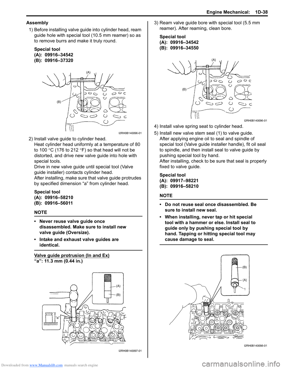
Assembly1) Before installing valve guide into cylinder head, ream
guide hole with special tool (10.5 mm reamer) so as
to remove burrs and make it truly round.
Special tool
(A): 09916–34542
(B): 09916–37320
2) Install valve guide to cylinder head. Heat cylinder head uniformly at a temperature of 80
to 100 °C (176 to 212 °F) so that head will not be
distorted, and drive new valve guide into hole with
special tools.
Drive in new valve guide until special tool (Valve
guide installer) contacts cylinder head.
After installing, ma ke sure that valve guide pr otrudes
by specified dimension “a” from cylinder head.
Special tool
(A): 09916–58210
(B): 09916–56011
NOTE
• Never reuse valve guide once disassembled. Make sure to install new
valve guide (Oversize).
• Intake and exhaust valve guides are identical.
Valve guide protrusion (In and Ex)
“a”: 11.3 mm (0.44 in.) 3) Ream valve guide bore with special tool (5.5 mm
reamer). After reaming, clean bore.
Special tool
(A): 09916–34542
(B): 09916–34550
4) Install valve spring seat to cylinder head.
5) Install new valve stem seal (1) to valve guide. After applying engine oil to seal and spindle of
special tool (Valve guide installer handle), fit oil seal
to spindle, and then install seal to valve guide by
pushing special tool by hand.
After installing, check to be sure that seal is properly
fixed to valve guide.
Special tool
(A): 09917–98221
(B): 09916–58210
NOTE
• Do not reuse seal once disassembled. Be sure to install new seal.
• When installing, never tap or hit special tool with a hammer or else. Install seal to
guide only by pushing special tool by
hand. Tapping or hitting special tool may
cause damage to seal.
I2RH0B140096-01
I2RH0B140097-01
I2RH0B140096-01
I2RH0B140098-01
Page 324 of 1496
Downloaded from www.Manualslib.com manuals search engine 1D-39 Engine Mechanical:
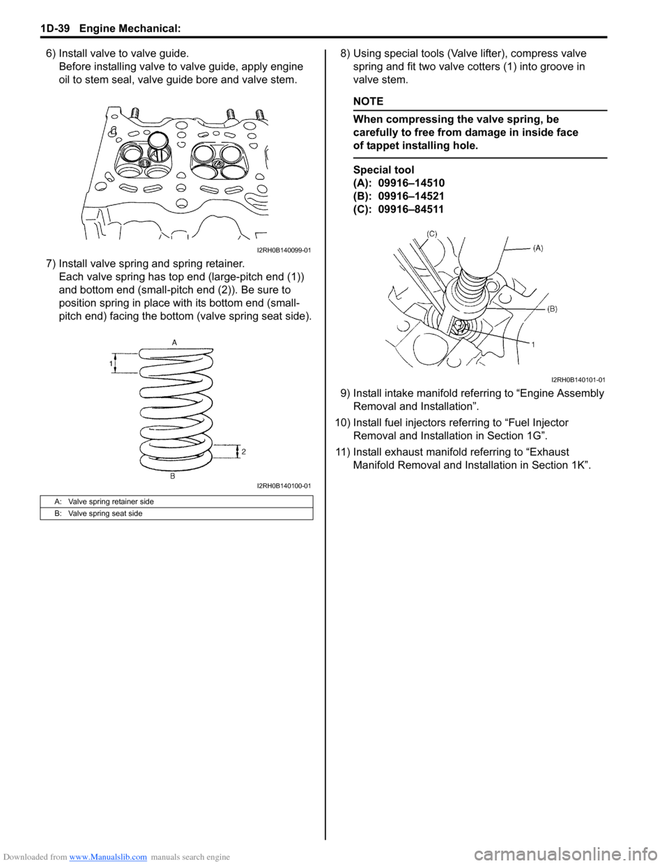
6) Install valve to valve guide.Before installing valve to valve guide, apply engine
oil to stem seal, valve guide bore and valve stem.
7) Install valve spring and spring retainer. Each valve spring has top end (large-pitch end (1))
and bottom end (small-pitch end (2)). Be sure to
position spring in place with its bottom end (small-
pitch end) facing the bottom (valve spring seat side). 8) Using special tools (Val
ve lifter), compress valve
spring and fit two valve cotters (1) into groove in
valve stem.
NOTE
When compressing the valve spring, be
carefully to free from damage in inside face
of tappet installing hole.
Special tool
(A): 09916–14510
(B): 09916–14521
(C): 09916–84511
9) Install intake manifold referring to “Engine Assembly Removal and Installation”.
10) Install fuel injectors referring to “Fuel Injector Removal and Installati on in Section 1G”.
11) Install exhaust manifold referring to “Exhaust Manifold Removal and Inst allation in Section 1K”.
A: Valve spring retainer side
B: Valve spring seat side
I2RH0B140099-01
I2RH0B140100-01
I2RH0B140101-01
Page 326 of 1496
Downloaded from www.Manualslib.com manuals search engine 1D-41 Engine Mechanical:
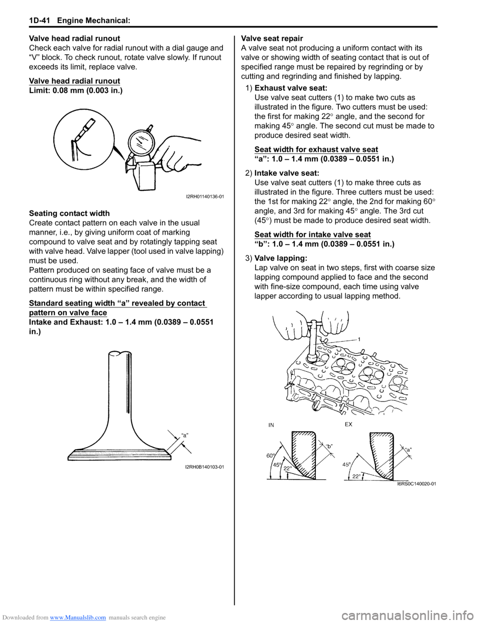
Valve head radial runout
Check each valve for radial runout with a dial gauge and
“V” block. To check runout, rotate valve slowly. If runout
exceeds its limit, replace valve.
Valve head radial runout
Limit: 0.08 mm (0.003 in.)
Seating contact width
Create contact pattern on each valve in the usual
manner, i.e., by giving uniform coat of marking
compound to valve seat and by rotatingly tapping seat
with valve head. Valve lapper (tool used in valve lapping)
must be used.
Pattern produced on seating face of valve must be a
continuous ring without any break, and the width of
pattern must be within specified range.
Standard seating width “a” revealed by contact
pattern on valve face
Intake and Exhaust: 1.0 – 1.4 mm (0.0389 – 0.0551
in.)Valve seat repair
A valve seat not producing
a uniform contact with its
valve or showing width of seating contact that is out of
specified range must be repaired by regrinding or by
cutting and regrinding and finished by lapping.
1) Exhaust valve seat:
Use valve seat cutters (1 ) to make two cuts as
illustrated in the figure. Two cutters must be used:
the first for making 22 ° angle, and the second for
making 45 ° angle. The second cut must be made to
produce desired seat width.
Seat width for exhaust valve seat
“a”: 1.0 – 1.4 mm (0.0389 – 0.0551 in.)
2) Intake valve seat:
Use valve seat cutters (1) to make three cuts as
illustrated in the figure. Th ree cutters must be used:
the 1st for making 22 ° angle, the 2nd for making 60 °
angle, and 3rd for making 45 ° angle. The 3rd cut
(45 °) must be made to produce desired seat width.
Seat width for intake valve seat
“b”: 1.0 – 1.4 mm (0.0389 – 0.0551 in.)
3) Valve lapping:
Lap valve on seat in two steps, first with coarse size
lapping compound applied to face and the second
with fine-size compound, each time using valve
lapper according to usual lapping method.
I2RH01140136-01
I2RH0B140103-01
I6RS0C140020-01
Page 327 of 1496
Downloaded from www.Manualslib.com manuals search engine Engine Mechanical: 1D-42
Cylinder Head InspectionS7RS0B1406027
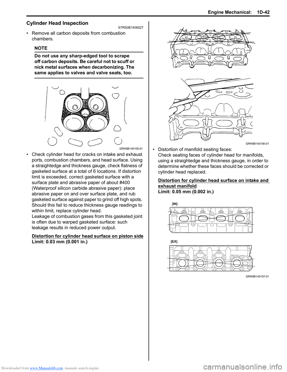
• Remove all carbon deposits from combustion chambers.
NOTE
Do not use any sharp-edged tool to scrape
off carbon deposits. Be careful not to scuff or
nick metal surfaces when decarbonizing. The
same applies to valves and valve seats, too.
• Check cylinder head for cracks on intake and exhaust ports, combustion chambers, and head surface. Using
a straightedge and thickness gauge, check flatness of
gasketed surface at a total of 6 locations. If distortion
limit is exceeded, correct gasketed surface with a
surface plate and abrasive paper of about #400
(Waterproof silicon carbide abrasive paper): place
abrasive paper on and over surface plate, and rub
gasketed surface against paper to grind off high spots.
Should this fail to reduce thickness gauge readings to
within limit, replace cylinder head.
Leakage of combustion gases from this gasketed joint
is often due to warped gasketed surface: such
leakage results in reduced power output.
Distortion for cylinder head surface on piston side
Limit: 0.03 mm (0.001 in.) • Distortion of manifold seating faces:
Check seating faces of cylinder head for manifolds,
using a straightedge and thickness gauge, in order to
determine whether these faces should be corrected or
cylinder head replaced.
Distortion for cylinder head surface on intake and
exhaust manifold
Limit: 0.05 mm (0.002 in.)
I2RH0B140105-01
I2RH0B140106-01
I2RH0B140107-01
Page 328 of 1496
Downloaded from www.Manualslib.com manuals search engine 1D-43 Engine Mechanical:
Valve Spring InspectionS7RS0B1406028
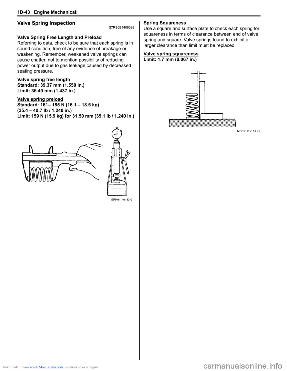
Valve Spring Free Length and Preload
Referring to data, check to be sure that each spring is in
sound condition, free of any evidence of breakage or
weakening. Remember, weakened valve springs can
cause chatter, not to mention possibility of reducing
power output due to gas leakage caused by decreased
seating pressure.
Valve spring free length
Standard: 39.37 mm (1.550 in.)
Limit: 36.49 mm (1.437 in.)
Valve spring preload
Standard: 161– 185 N (16.1 – 18.5 kg)
(35.4 – 40.7 lb / 1.240 in.)
Limit: 159 N (15.9 kg) for 31.50 mm (35.1 lb / 1.240 in.) Spring Squareness
Use a square and surface plate to check each spring for
squareness in terms of clearance between end of valve
spring and square. Valve springs found to exhibit a
larger clearance than limit must be replaced.
Valve spring squareness
Limit: 1.7 mm (0.067 in.)
I2RH01140143-01
I2RH01140144-01
Page 348 of 1496
Downloaded from www.Manualslib.com manuals search engine 1D-63 Engine Mechanical:
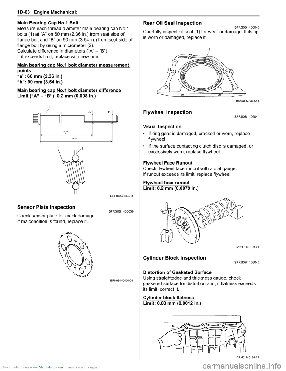
Main Bearing Cap No.1 Bolt
Measure each thread diameter main bearing cap No.1
bolts (1) at “A” on 60 mm (2.36 in.) from seat side of
flange bolt and “B” on 90 mm (3.54 in.) from seat side of
flange bolt by using a micrometer (2).
Calculate difference in diameters (“A” – “B”).
If it exceeds limit, replace with new one.
Main bearing cap No.1 bolt diameter measurement
points
“a”: 60 mm (2.36 in.)
“b”: 90 mm (3.54 in.)
Main bearing cap No.1 bolt diameter difference
Limit (“A” – “B”): 0.2 mm (0.008 in.)
Sensor Plate InspectionS7RS0B1406039
Check sensor plate for crack damage.
If malcondition is found, replace it.
Rear Oil Seal InspectionS7RS0B1406040
Carefully inspect oil seal (1) for wear or damage. If its lip
is worn or damaged, replace it.
Flywheel InspectionS7RS0B1406041
Visual Inspection
• If ring gear is damaged, cracked or worn, replace flywheel.
• If the surface contacting cl utch disc is damaged, or
excessively worn, replace flywheel.
Flywheel Face Runout
Check flywheel face runout with a dial gauge.
If runout exceeds its limit, replace flywheel.
Flywheel face runout
Limit: 0.2 mm (0.0079 in.)
Cylinder Block InspectionS7RS0B1406042
Distortion of Gasketed Surface
Using straightedge and thickness gauge, check
gasketed surface for distortion and, if flatness exceeds
its limit, correct It.
Cylinder block flatness
Limit: 0.03 mm (0.0012 in.)
“A”
“a” “b” “B”
1
1
2
I2RH0B140145-01
I2RH0B140151-01
I4RS0A140020-01
I2RH01140198-01
I2RH01140199-01
Page 371 of 1496
Downloaded from www.Manualslib.com manuals search engine Engine Cooling System: 1F-8
Thermostat Removal and InstallationS7RS0B1606007
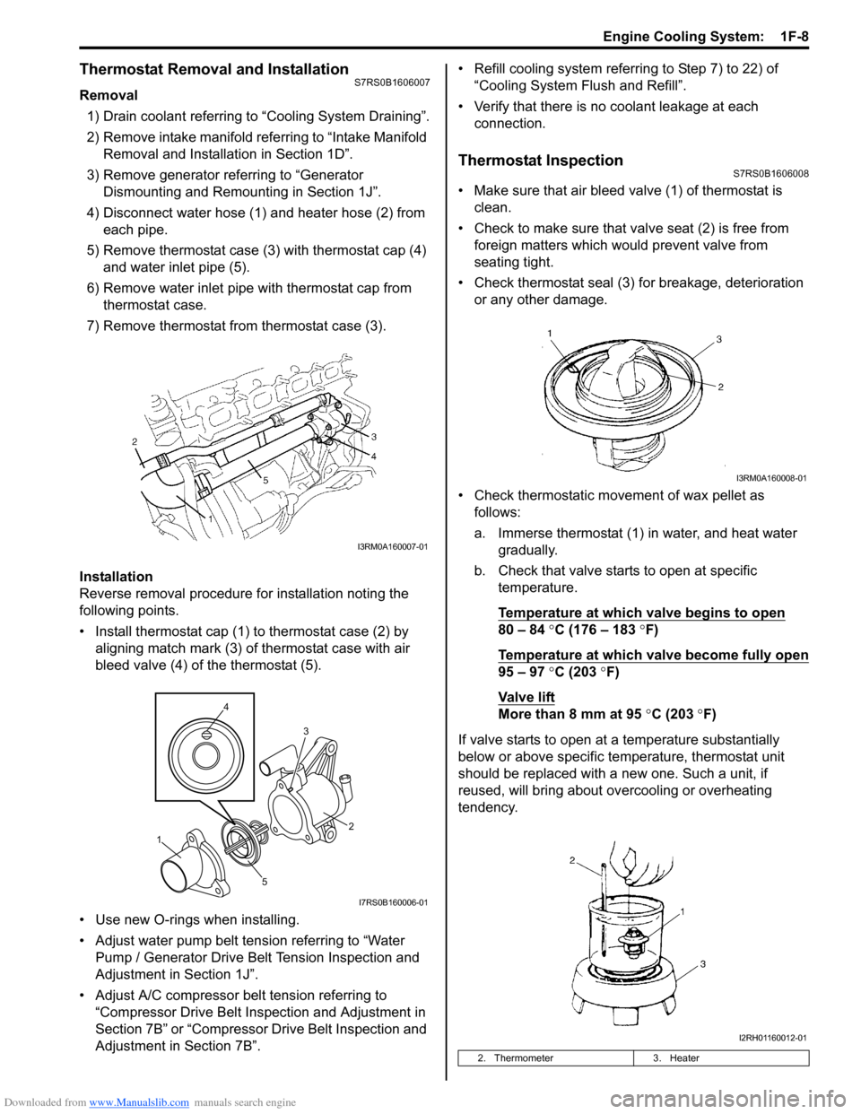
Removal1) Drain coolant referring to “Cooling System Draining”.
2) Remove intake manifold referring to “Intake Manifold Removal and Installa tion in Section 1D”.
3) Remove generator referring to “Generator Dismounting and Remounting in Section 1J”.
4) Disconnect water hose (1) and heater hose (2) from each pipe.
5) Remove thermostat case (3) with thermostat cap (4)
and water inlet pipe (5).
6) Remove water inlet pipe with thermostat cap from thermostat case.
7) Remove thermostat from thermostat case (3).
Installation
Reverse removal procedure for installation noting the
following points.
• Install thermostat cap (1) to thermostat case (2) by aligning match mark (3) of thermostat case with air
bleed valve (4) of the thermostat (5).
• Use new O-rings when installing.
• Adjust water pump belt tension referring to “Water Pump / Generator Drive Belt Tension Inspection and
Adjustment in Section 1J”.
• Adjust A/C compressor belt tension referring to “Compressor Drive Belt Inspection and Adjustment in
Section 7B” or “Compressor Drive Belt Inspection and
Adjustment in Section 7B”. • Refill cooling system referrin
g to Step 7) to 22) of
“Cooling System Flush and Refill”.
• Verify that there is no coolant leakage at each connection.
Thermostat InspectionS7RS0B1606008
• Make sure that air bleed valve (1) of thermostat is clean.
• Check to make sure that va lve seat (2) is free from
foreign matters which would prevent valve from
seating tight.
• Check thermostat seal (3) for breakage, deterioration or any other damage.
• Check thermostatic movement of wax pellet as follows:
a. Immerse thermostat (1) in water, and heat water gradually.
b. Check that valve starts to open at specific temperature.
Temperature at which valve begins to open
80 – 84 °C (176 – 183 °F)
Temperature at which valve become fully open
95 – 97 °C (203 °F)
Va l v e l i ft
More than 8 mm at 95 °C (203 ° F)
If valve starts to open at a temperature substantially
below or above specific temperature, thermostat unit
should be replaced with a new one. Such a unit, if
reused, will bring about ov ercooling or overheating
tendency.
I3RM0A160007-01
4
5 3
1 2
I7RS0B160006-01
2. Thermometer
3. Heater
I3RM0A160008-01
I2RH01160012-01
Page 403 of 1496
Downloaded from www.Manualslib.com manuals search engine Starting System: 1I-2
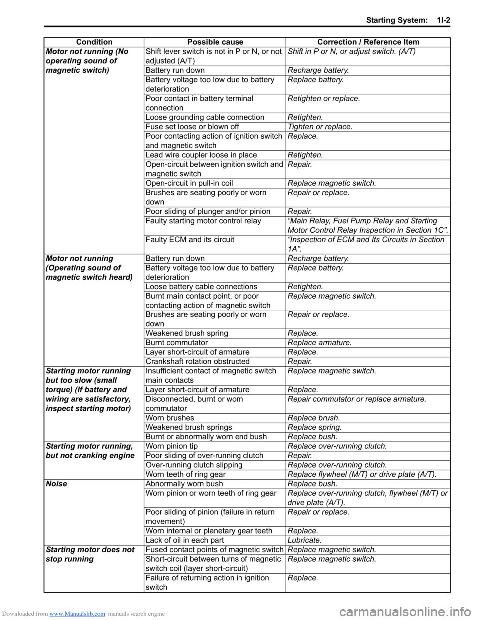
ConditionPossible cause Correction / Reference Item
Motor not running (No
operating sound of
magnetic switch) Shift lever switch is not in P or N, or not
adjusted (A/T)
Shift in P or N, or
adjust switch. (A/T)
Battery run down Recharge battery.
Battery voltage too low due to battery
deterioration Replace battery.
Poor contact in battery terminal
connection Retighten or replace.
Loose grounding cable connection Retighten.
Fuse set loose or blown off Tighten or replace.
Poor contacting action of ignition switch
and magnetic switch Replace.
Lead wire coupler loose in place Retighten.
Open-circuit between ignition switch and
magnetic switch Repair.
Open-circuit in pull-in coil Replace magnetic switch.
Brushes are seating poorly or worn
down Repair or replace.
Poor sliding of plunger and/or pinion Repair.
Faulty starting motor control relay “Main Relay, Fuel Pump Relay and Starting
Motor Control Relay Inspection in Section 1C”.
Faulty ECM and its circuit “Inspection of ECM and Its Circuits in Section
1A”.
Motor not running
(Operating sound of
magnetic switch heard) Battery run down
Recharge battery.
Battery voltage too low due to battery
deterioration Replace battery.
Loose battery cable connections Retighten.
Burnt main contact point, or poor
contacting action of magnetic switch Replace magnetic switch.
Brushes are seating poorly or worn
down Repair or replace.
Weakened brush spring Replace.
Burnt commutator Replace armature.
Layer short-circuit of armature Replace.
Crankshaft rotation obstructed Repair.
Starting motor running
but too slow (small
torque) (If battery and
wiring are satisfactory,
inspect starting motor) Insufficient contact
of magnetic switch
main contacts Replace magnetic switch.
Layer short-circuit of armature Replace.
Disconnected, burnt or worn
commutator Repair commutator or replace armature.
Worn brushes Replace brush.
Weakened brush springs Replace spring.
Burnt or abnormally worn end bush Replace bush.
Starting motor running,
but not cranking engine Worn pinion tip
Replace over-running clutch.
Poor sliding of over-running clutch Repair.
Over-running clutch slipping Replace over-running clutch.
Worn teeth of ring gear Replace flywheel (M/T) or drive plate (A/T).
Noise Abnormally worn bush Replace bush.
Worn pinion or worn teeth of ring gear Replace over-running clutch, flywheel (M/T) or
drive plate (A/T).
Poor sliding of pinion (failure in return
movement) Repair or replace.
Worn internal or planetary gear teeth Replace.
Lack of oil in each part Lubricate.
Starting motor does not
stop running Fused contact points of magnetic switch
Replace magnetic switch.
Short-circuit between turns of magnetic
switch coil (layer short-circuit) Replace magnetic switch.
Failure of returning action in ignition
switch Replace.