Page 1360 of 1496
Downloaded from www.Manualslib.com manuals search engine 9F-14 Security and Locks:
Keyless Entry Answer Back Function Change-
over Procedure (If Equipped)
S7RS0B9606016
Output of keyless entry answer back function can be
switched over by performing the following procedure.
1) Confirm that all doors are closed, all doors are unlocked, ignition key is out of ignition key cylinder
and interior light switch is in the middle position.
2) Perform Step a) through c) described below within 10 seconds.
a) Insert ignition key in ignition key cylinder.
b) Remove ignition key from ignition key cylinder.
c) Repeat Step a) and b) once.
3) Push “UNLOCK” button on transmitter 3 times within 10 seconds.
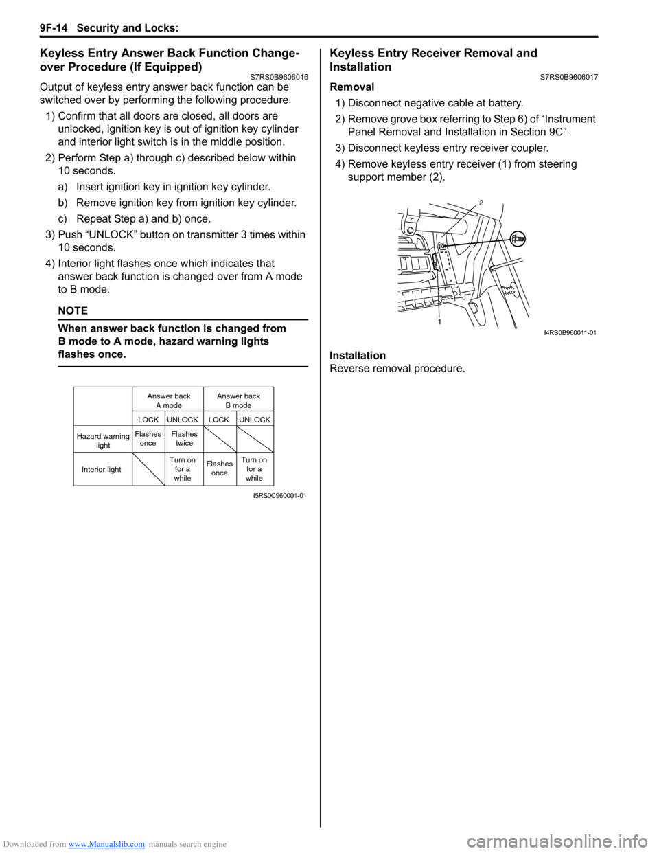
4) Interior light flashes once which indicates that answer back function is changed over from A mode
to B mode.
NOTE
When answer back function is changed from
B mode to A mode, hazard warning lights
flashes once.
Keyless Entry Receiver Removal and
Installation
S7RS0B9606017
Removal
1) Disconnect negative cable at battery.
2) Remove grove box referring to Step 6) of “Instrument Panel Removal and Installation in Section 9C”.
3) Disconnect keyless entry receiver coupler.
4) Remove keyless entry receiver (1) from steering support member (2).
Installation
Reverse removal procedure.
Hazard warning light
LOCK LOCK
UNLOCK UNLOCK
Interior lightFlashes
once Flashes
twice
Flashesonce
Turn on
for a
while Turn on
for a
while
Answer back
A mode Answer back
B mode
I5RS0C960001-01
1 2I4RS0B960011-01
Page 1362 of 1496
Downloaded from www.Manualslib.com manuals search engine 9F-16 Security and Locks:
Specifications
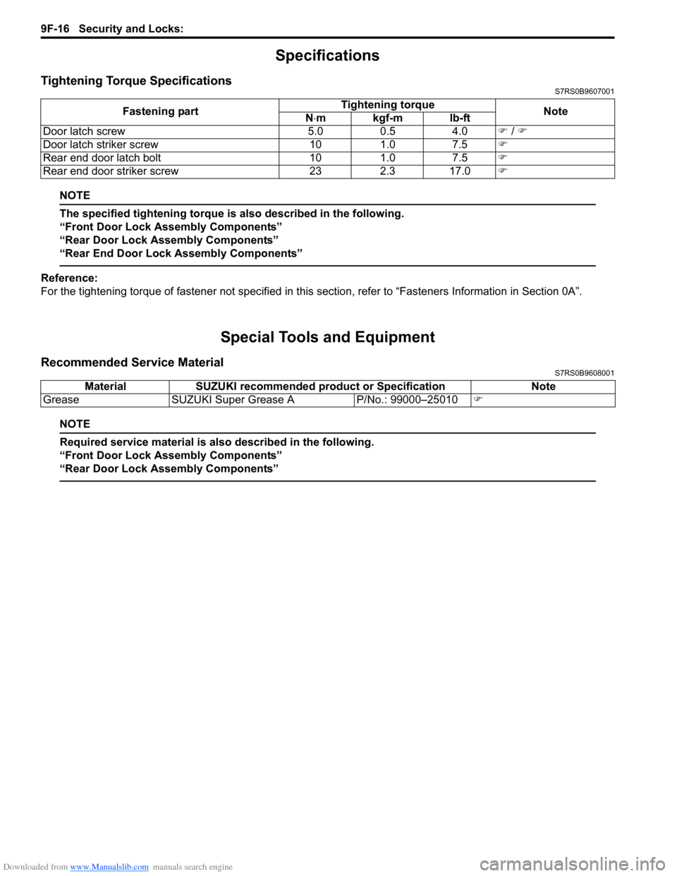
Tightening Torque SpecificationsS7RS0B9607001
NOTE
The specified tightening torque is also described in the following.
“Front Door Lock Assembly Components”
“Rear Door Lock Assembly Components”
“Rear End Door Lock Assembly Components”
Reference:
For the tightening torque of fastener not specified in this section, refer to “Fasteners Information in Section 0A”.
Special Tools and Equipment
Recommended Service MaterialS7RS0B9608001
NOTE
Required service material is also described in the following.
“Front Door Lock Assembly Components”
“Rear Door Lock Assembly Components”
Fastening part Tightening torque
Note
N ⋅mkgf-mlb-ft
Door latch screw 5.0 0.5 4.0 �) / �)
Door latch striker screw 10 1.0 7.5 �)
Rear end door latch bolt 10 1.0 7.5 �)
Rear end door striker screw 23 2.3 17.0 �)
MaterialSUZUKI recommended product or Specification Note
Grease SUZUKI Super Grease A P/No.: 99000–25010�)
Page 1370 of 1496
Downloaded from www.Manualslib.com manuals search engine 9J-1 Hood / Fenders / Doors:
Body, Cab and Accessories
Hood / Fenders / Doors
Repair Instructions
Hood Removal and InstallationS7RS0B9A06001
Removal
CAUTION!
Place cloth to prevent body from any
damage.
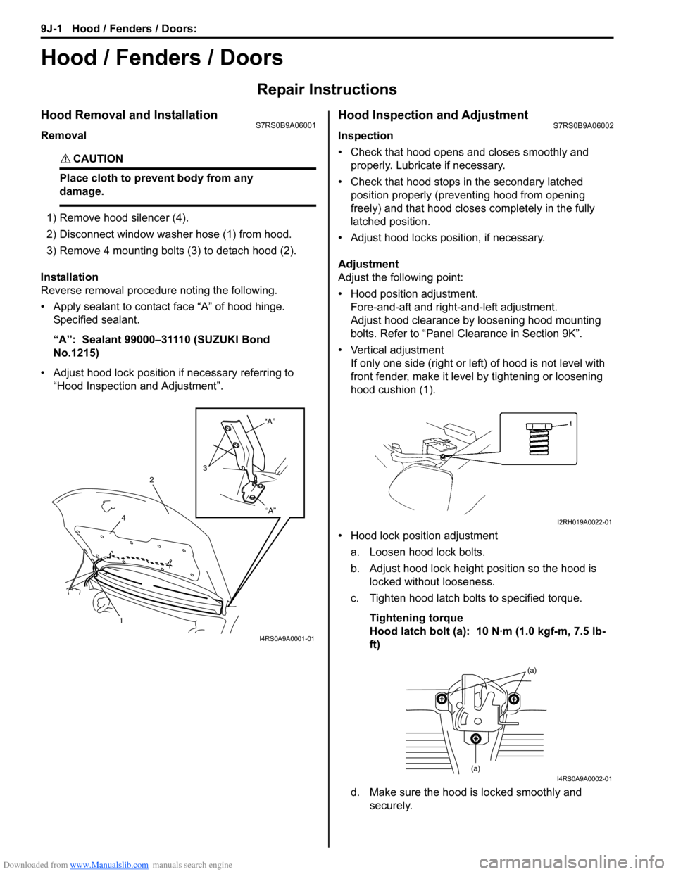
1) Remove hood silencer (4).
2) Disconnect window washer hose (1) from hood.
3) Remove 4 mounting bolts (3) to detach hood (2).
Installation
Reverse removal procedure noting the following.
• Apply sealant to contact face “A” of hood hinge. Specified sealant.
“A”: Sealant 99000–31110 (SUZUKI Bond
No.1215)
• Adjust hood lock position if necessary referring to “Hood Inspection and Adjustment”.
Hood Inspection and AdjustmentS7RS0B9A06002
Inspection
• Check that hood opens and closes smoothly and properly. Lubricate if necessary.
• Check that hood stops in the secondary latched position properly (preventing hood from opening
freely) and that hood closes completely in the fully
latched position.
• Adjust hood locks position, if necessary.
Adjustment
Adjust the following point:
• Hood position adjustment. Fore-and-aft and right-and-left adjustment.
Adjust hood clearance by loosening hood mounting
bolts. Refer to “Panel Clearance in Section 9K”.
• Vertical adjustment If only one side (right or left) of hood is not level with
front fender, make it level by tightening or loosening
hood cushion (1).
• Hood lock position adjustment a. Loosen hood lock bolts.
b. Adjust hood lock height position so the hood is locked without looseness.
c. Tighten hood latch bolts to specified torque.
Tightening torque
Hood latch bolt (a): 10 N·m (1.0 kgf-m, 7.5 lb-
ft)
d. Make sure the hood is locked smoothly and securely.
“A”
“A”
3
2
4
1
I4RS0A9A0001-01
I2RH019A0022-01
(a)
(a)I4RS0A9A0002-01
Page 1465 of 1496
Downloaded from www.Manualslib.com manuals search engine Keyless Start System: 10E-3
Keyless Engine Start FunctionS7RS0BA501003
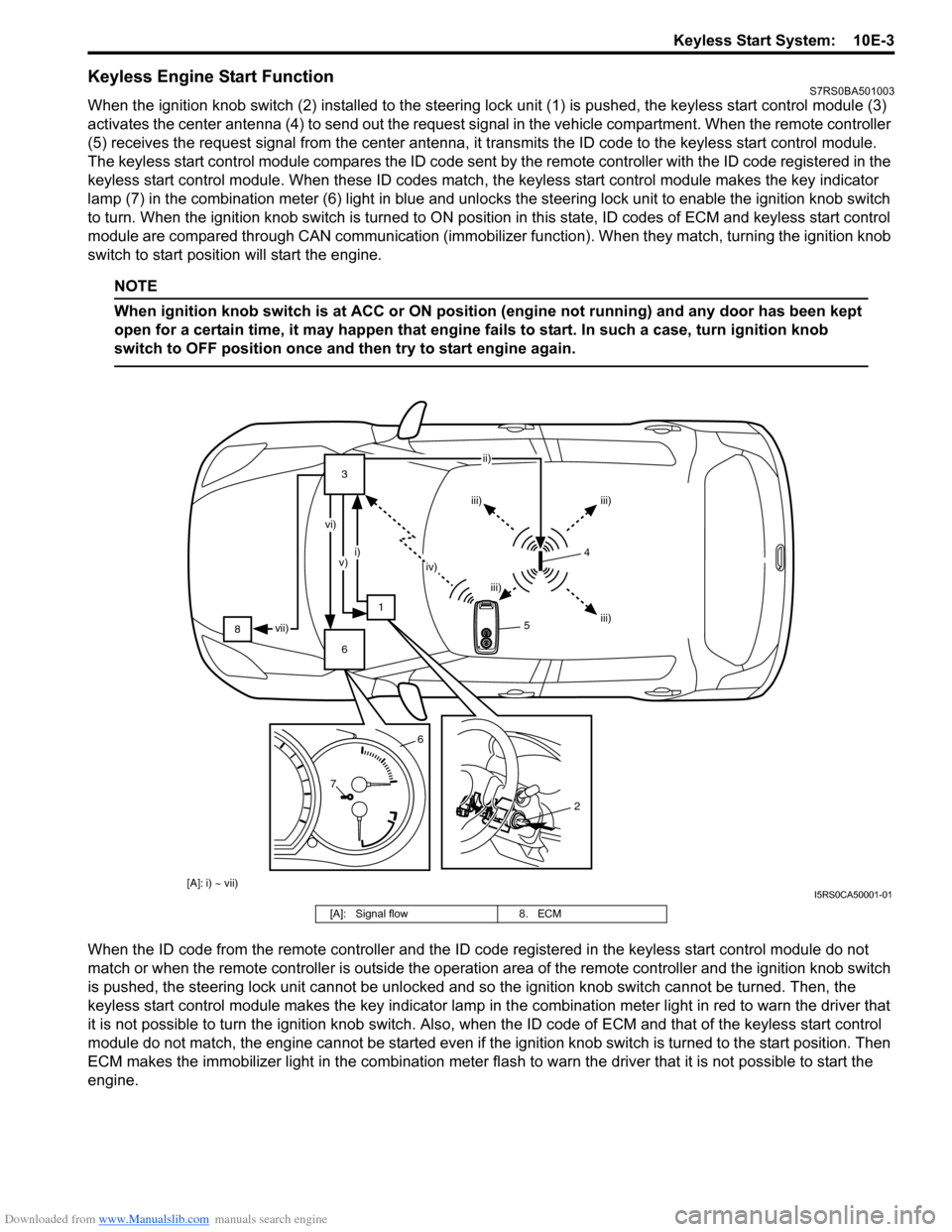
When the ignition knob switch (2) installed to the steering lock unit (1) is pushed, the keyless start control module (3)
activates the center antenna (4) to send out the request signa l in the vehicle compartment. When the remote controller
(5) receives the request signal from th e center antenna, it transmits the ID code to the keyless start control module.
The keyless start control module compares the ID code sent by the remote controller with the ID code registered in the
keyless start control module. When these ID codes match, the keyless start control module makes the key indicator
lamp (7) in the combination meter (6) light in blue and unlocks the steering lock unit to enable the ignition knob switch
to turn. When the ignition knob switch is turned to ON posit ion in this state, ID codes of ECM and keyless start control
module are compared through CA N communication (immobilizer function). Wh en they match, turning the ignition knob
switch to start position will start the engine.
NOTE
When ignition knob switch is at ACC or ON position (engine not running) and any door has been kept
open for a certain time, it may happen that engine fails to start. In such a case, turn ignition knob
switch to OFF position once and then try to start engine again.
When the ID code from the remote controller and the ID code registered in the keyless start control module do not
match or when the remote controller is outside the operation area of the remote controller and the ignition knob switch
is pushed, the steering lock unit cannot be unlocked and so the ignition knob switch cannot be turned. Then, the
keyless start control module makes the key indicator lamp in t he combination meter light in red to warn the driver that
it is not possible to turn the ignition knob switch. Also, when the ID code of ECM and that of the keyless start control
module do not match, the engine cannot be started even if the ignition knob switch is turned to the start position. Then
ECM makes the immobilizer light in the combination mete r flash to warn the driver that it is not possible to start the
engine.
8 3
1
6 ii)
iii) iii)
iii)
iii)
iv)
i)
v)
vi)
vii)
7 6
2
[A]: i) ~ vii)
54
I5RS0CA50001-01
[A]: Signal flow
8. ECM
Page 1476 of 1496
Downloaded from www.Manualslib.com manuals search engine 10E-14 Keyless Start System:
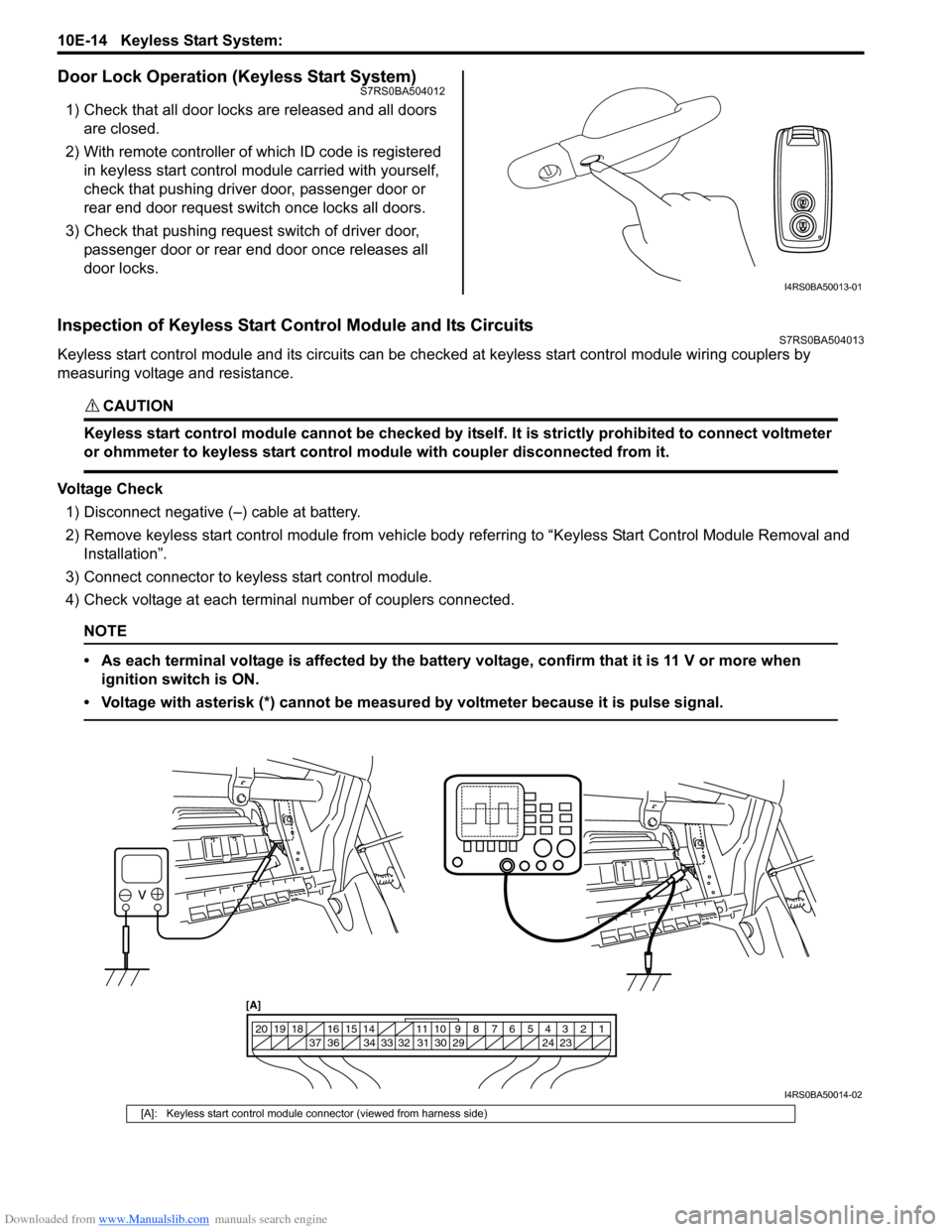
Door Lock Operation (Keyless Start System)S7RS0BA504012
1) Check that all door locks are released and all doors are closed.
2) With remote controller of which ID code is registered in keyless start control m odule carried with yourself,
check that pushing driver door, passenger door or
rear end door request switch once locks all doors.
3) Check that pushing request switch of driver door, passenger door or rear end door once releases all
door locks.
Inspection of Keyless Start Control Module and Its CircuitsS7RS0BA504013
Keyless start control module and its circuits can be che cked at keyless start control module wiring couplers by
measuring voltage and resistance.
CAUTION!
Keyless start control module cannot be checked by itself. It is strictly prohibited to connect voltmeter
or ohmmeter to keyless start control module with coupler disconnected from it.
Voltage Check
1) Disconnect negative (–) cable at battery.
2) Remove keyless start control module from vehicle body referring to “Keyless Start Control Module Removal and
Installation”.
3) Connect connector to keyless start control module.
4) Check voltage at each terminal number of couplers connected.
NOTE
• As each terminal voltage is affected by the battery voltage, confirm that it is 11 V or more when ignition switch is ON.
• Voltage with asterisk (*) cannot be measured by voltmeter because it is pulse signal.
I4RS0BA50013-01
1234567891011
141516
36 34 33 32 31 30 29 24 23
37
181920
[A]
I4RS0BA50014-02
[A]: Keyless start control module connector (viewed from harness side)
Page:
< prev 1-8 9-16 17-24