Page 339 of 1496

Downloaded from www.Manualslib.com manuals search engine Engine Mechanical: 1D-54
Main Bearings, Crankshaft and Cylinder Block
Removal and Installation
S7RS0B1406036
Removal1) Remove engine assembly from vehicle referring to “Engine Assembly Removal and Installation”.
2) Remove clutch cover, clut ch disc and flywheel (drive
plate for A/T) by using special tool.
Special tool
(A): 09924–17811
3) Remove piston and connecting rod referring to “Pistons, Piston Rings, Connecting Rods and
Cylinders Removal and Installation”.
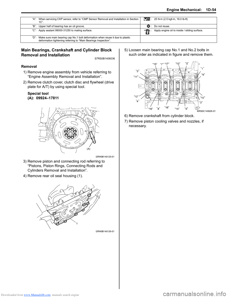
4) Remove rear oil seal housing (1). 5) Loosen main bearing cap No.1 and No.2 bolts in
such order as indicated in figure and remove them.
6) Remove crankshaft from cylinder block.
7) Remove piston cooling valves and nozzles, if necessary.
“A”: When servicing CKP sensor, refer to “CMP Sensor Removal and Installation in Section 1C”. :25 N
⋅m (2.5 kgf-m, 18.0 lb-ft)
“B”: Upper half of bearing has an oil groove. : Do not reuse.
“C”: Apply sealant 99000-31250 to mating surface. : Apply engine oil to inside / sliding surface.
“D”: Make sure main bearing cap No.1 bolt deformation when reuse it due to plastic deformation tightening referring to “Main Bearings Inspection”.
I2RH0B140125-01
I2RH0B140126-01
I6RS0C140026-01
Page 357 of 1496

Downloaded from www.Manualslib.com manuals search engine Engine Lubrication System: 1E-5
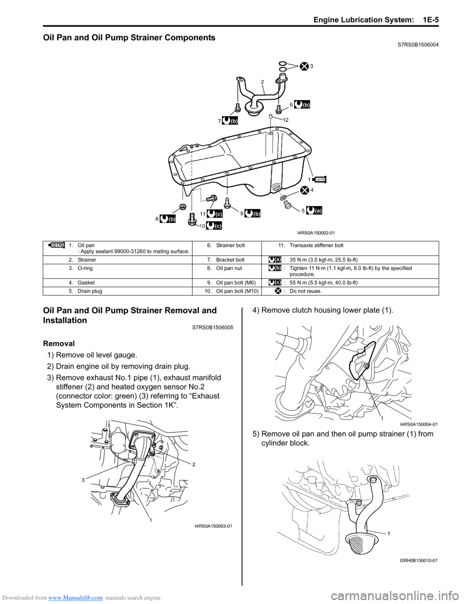
Oil Pan and Oil Pump Strainer ComponentsS7RS0B1506004
Oil Pan and Oil Pump Strainer Removal and
Installation
S7RS0B1506005
Removal1) Remove oil level gauge.
2) Drain engine oil by removing drain plug.
3) Remove exhaust No.1 pipe (1), exhaust manifold stiffener (2) and heated oxygen sensor No.2
(connector color: green) (3) referring to “Exhaust
System Components in Section 1K”. 4) Remove clutch housing lower plate (1).
5) Remove oil pan and then oil pump strainer (1) from
cylinder block.
I4RS0A150002-01
1. Oil pan : Apply sealant 99000-31260 to mating surface. 6. Strainer bolt 11. Transaxle stiffener bolt
2. Strainer 7. Bracket bolt : 35 N ⋅m (3.5 kgf-m, 25.5 lb-ft)
3. O-ring 8. Oil pan nut : Tighten 11 N ⋅m (1.1 kgf-m, 8.0 lb-ft) by the specified
procedure.
4. Gasket 9. Oil pan bolt (M6) : 55 N ⋅m (5.5 kgf-m, 40.0 lb-ft)
5. Drain plug 10. Oil pan bolt (M10) : Do not reuse.
2
1
3
I4RS0A150003-01
1I4RS0A150004-01
I2RH0B150010-01
Page 359 of 1496

Downloaded from www.Manualslib.com manuals search engine Engine Lubrication System: 1E-7
6) After fitting oil pan to cylinder block, run in securing bolts and start tightening at the center: move wrench
outward, tightening one bolt at a time. Tighten bolts
and nuts to specified torque.
Tightening torque
Oil pan bolt (M6) (a): 11 N·m (1.1 kgf-m, 8.0 lb-ft)
Oil pan bolt (M10) (c): 55 N·m (5.5 kgf-m, 40.0 lb-
ft)
Oil pan nut (e): 11 N·m (1.1 kgf-m, 8.0 lb-ft)
7) Install new gasket and drain plug to oil pan. Tighten drain plug to specified torque.
Tightening torque
Oil pan drain plug (b): 35 N·m (3.5 kgf-m, 25.5 lb-
ft)
8) Tighten transaxle stiffener bolts to specified torque. Tightening torque
Transaxle stiffener bolt (d): 55 N·m (5.5 kgf-m,
40.0 lb-ft)
9) Install exhaust manifold stiffener (2) and exhaust No.1 pipe (1) and heated oxygen sensor No.2
(connector color: green) (3) referring to “Exhaust
System Components in Section 1K”. 10) Install clutch housing lower plate (1).
11) Install oil level gauge.
12) Refill engine with engine oil referring to “Engine Oil
and Filter Change in Section 0B”.
13) Verify that there is no en gine oil leakage and exhaust
gas leakage at each connection.
Oil Pan and Oil Pump Strainer CleaningS7RS0B1506006
• Clean sealing surface between oil pan and cylinder block.
Remove oil, old sealant, and dust from sealing
surface.
• Clean oil pump strainer screen (1).(a)
(b)
(c)(e)
(d)I4RS0A150008-01
2
1
3
I4RS0A150003-01
1I4RS0A150004-01
I2RH0B150016-01
Page 367 of 1496

Downloaded from www.Manualslib.com manuals search engine Engine Cooling System: 1F-4
Diagnostic Information and Procedures
Engine Cooling Symptom DiagnosisS7RS0B1604001
ConditionPossible cause Correction / Reference Item
Engine overheats
(Radiator fan operates) Loose or broken water pump belt
Adjust or replace.
Not enough coolant Check coolant level and add as necessary.
Faulty thermostat Replace.
Faulty water pump Replace.
Dirty or bent radiator fins Clean or remedy.
Coolant leakage on cooling system Repair.
Clogged radiator Check and replace radiator as necessary.
Faulty radiator cap Replace.
Improper ignition timing Adjust.
Dragging brakes Adjust brake.
Slipping clutch Adjust or replace.
Poor charge battery Check and replace as necessary.
Poor generation generator Check and repair.
ECT sensor faulty Check and replace as necessary.
Radiator cooling fan relay No.2 and/or
No.3 faulty Check and replace as necessary.
Radiator fan motor faulty Check and replace as necessary.
ECM faulty Check and replace as necessary.
Wiring or grounding faulty Repair as necessary.
Equipped with too much electric load
part(s) Dismount.
Engine overheats
(Radiator fan does not
operate) Fuse blown
Check 30 A fuse of relay/fuse box and check
for short circuit to ground.
Radiator cooling fan relay No.1 faulty Check and replace as necessary.
ECT sensor faulty Check and replace as necessary.
Radiator cooling fan motor faulty Check and replace as necessary.
Wiring or grounding faulty Repair as necessary.
ECM faulty Check and replace as necessary.
Page 402 of 1496

Downloaded from www.Manualslib.com manuals search engine 1I-1 Starting System:
Engine
Starting System
Schematic and Routing Diagram
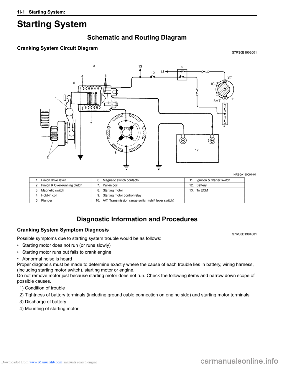
Cranking System Circuit DiagramS7RS0B1902001
Diagnostic Information and Procedures
Cranking System Symptom DiagnosisS7RS0B1904001
Possible symptoms due to starting system trouble would be as follows:
• Starting motor does not run (or runs slowly)
• Starting motor runs but fails to crank engine
• Abnormal noise is heard
Proper diagnosis must be made to determine exactly where the cause of each trouble lies in battery, wiring harness,
(including starting motor switch), starting motor or engine.
Do not remove motor just because starting motor does not run. Check the following items and narrow down scope of
possible causes.
1) Condition of trouble
2) Tightness of battery terminals (including ground cable connection on engine side) and starting motor terminals
3) Discharge of battery
4) Mounting of starting motor
I4RS0A190001-01
1. Pinion drive lever 6. Magnetic switch contacts 11. Ignition & Starter switch
2. Pinion & Over-running clutch 7. Pull-in coil 12. Battery
3. Magnetic switch 8. Starting motor 13. To ECM
4. Hold-in coil 9. Starting motor control relay
5. Plunger 10. A/T: Transmission range switch (shift lever switch)
Page 403 of 1496

Downloaded from www.Manualslib.com manuals search engine Starting System: 1I-2
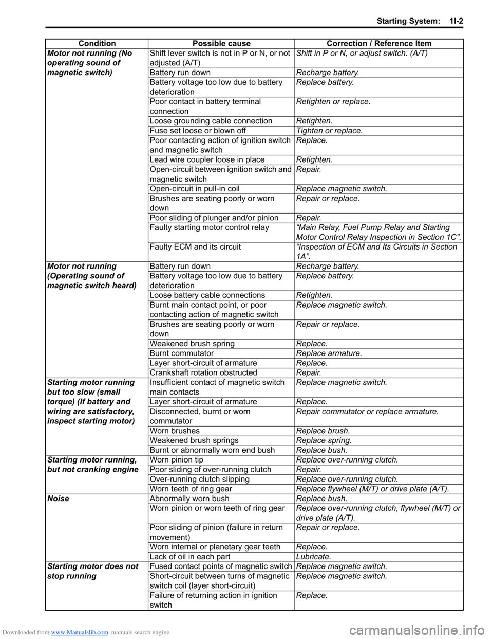
ConditionPossible cause Correction / Reference Item
Motor not running (No
operating sound of
magnetic switch) Shift lever switch is not in P or N, or not
adjusted (A/T)
Shift in P or N, or
adjust switch. (A/T)
Battery run down Recharge battery.
Battery voltage too low due to battery
deterioration Replace battery.
Poor contact in battery terminal
connection Retighten or replace.
Loose grounding cable connection Retighten.
Fuse set loose or blown off Tighten or replace.
Poor contacting action of ignition switch
and magnetic switch Replace.
Lead wire coupler loose in place Retighten.
Open-circuit between ignition switch and
magnetic switch Repair.
Open-circuit in pull-in coil Replace magnetic switch.
Brushes are seating poorly or worn
down Repair or replace.
Poor sliding of plunger and/or pinion Repair.
Faulty starting motor control relay “Main Relay, Fuel Pump Relay and Starting
Motor Control Relay Inspection in Section 1C”.
Faulty ECM and its circuit “Inspection of ECM and Its Circuits in Section
1A”.
Motor not running
(Operating sound of
magnetic switch heard) Battery run down
Recharge battery.
Battery voltage too low due to battery
deterioration Replace battery.
Loose battery cable connections Retighten.
Burnt main contact point, or poor
contacting action of magnetic switch Replace magnetic switch.
Brushes are seating poorly or worn
down Repair or replace.
Weakened brush spring Replace.
Burnt commutator Replace armature.
Layer short-circuit of armature Replace.
Crankshaft rotation obstructed Repair.
Starting motor running
but too slow (small
torque) (If battery and
wiring are satisfactory,
inspect starting motor) Insufficient contact
of magnetic switch
main contacts Replace magnetic switch.
Layer short-circuit of armature Replace.
Disconnected, burnt or worn
commutator Repair commutator or replace armature.
Worn brushes Replace brush.
Weakened brush springs Replace spring.
Burnt or abnormally worn end bush Replace bush.
Starting motor running,
but not cranking engine Worn pinion tip
Replace over-running clutch.
Poor sliding of over-running clutch Repair.
Over-running clutch slipping Replace over-running clutch.
Worn teeth of ring gear Replace flywheel (M/T) or drive plate (A/T).
Noise Abnormally worn bush Replace bush.
Worn pinion or worn teeth of ring gear Replace over-running clutch, flywheel (M/T) or
drive plate (A/T).
Poor sliding of pinion (failure in return
movement) Repair or replace.
Worn internal or planetary gear teeth Replace.
Lack of oil in each part Lubricate.
Starting motor does not
stop running Fused contact points of magnetic switch
Replace magnetic switch.
Short-circuit between turns of magnetic
switch coil (layer short-circuit) Replace magnetic switch.
Failure of returning action in ignition
switch Replace.
Page 406 of 1496
Downloaded from www.Manualslib.com manuals search engine 1I-5 Starting System:
Starting Motor ComponentsS7RS0B1906002
I4RS0A190003-01
1. Front housing 7. Plate 13. Planetary gear 19. Rear bush
2. Bush 8. Seal rubber 14. Packing 20. Starting motor battery cable nut
3. Pinion stop ring 9. Magnetic switch 15. Yoke :9.8 N
⋅m (0.98 kgf-m, 7.0 lb-ft)
4. Over-running clutch 10. Ball 16. Armature: Do not reuse.
5. Lever 11. Internal gear 17. Brush assembly : Apply grease 99000-25010 to sliding surface of each part.
6. Plunger 12. Planetary carrier shaft 18. Rear bracket
Page 409 of 1496
Downloaded from www.Manualslib.com manuals search engine Starting System: 1I-8
• Check the commutator and armature core. If there is
continuity, the armature is grounded and must be
replaced.
• Check for continuity between segments. If there is no continuity at any test point , there is an open circuit
and the armature must be replaced.
Gears
Inspect the internal gear and the planetary gears for
wear, damage or other abnorma l conditions. Replace if
necessary. Pinion and Over-Running Clutch
• Inspect the pinion for wear, damage or other abnormal
conditions.
Check that clutch locks up when turned in direction of
drive and rotates smoothly in reverse direction.
Replace if necessary.
• Inspect the spline teeth for wear or damage. Replace if necessary.
Inspect the pinion for smooth movement.
Front Housing Bush
Inspect the bush for wear or damage. Replace if
necessary.
I2RH01190019-01
I2RH01190020-01
I2RH01190021-01
I2RH01190022-01
I2RH01190023-01
I2RH01190024-01