Page 1204 of 1496
Downloaded from www.Manualslib.com manuals search engine 9A-33 Wiring Systems:
Fuses and the Protected PartsS7RS0B910D002
The chart below describes what parts each fuse protects.
Fuses in Main Fuse Box (RHD)S7RS0B910D003
Fuses in Main Fuse Box (LHD)S7RS0B910D004
No.Fuse Protected circuit
80 A All electric circuit
Battery
Generator
50 A LAMP
50 A IG switch
Supplementary fuse box No.2 (In J/B)
80 A Individual circuit fuse box
80 A Individual circuit fuse box
1
3
2
I4RS0A910905-01
2
3
47
46
1
I4RS0B910974-01
Page 1205 of 1496

Downloaded from www.Manualslib.com manuals search engine Wiring Systems: 9A-34
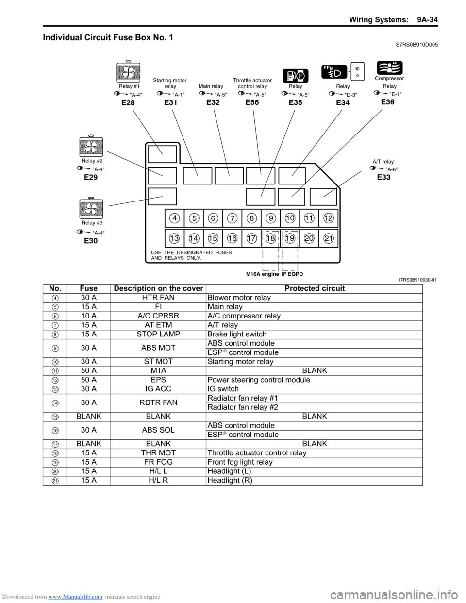
Individual Circuit Fuse Box No. 1S7RS0B910D005
456789101112
131415161718192021
USE THE DESINGNATED FUSES
AND RELAYS ONLY.
Relay #1
"A-4"
E28
Relay #2
"A-4"
E29
Relay #3
"A-4"
E30
"A-5"
E35
RelayRelay
"D-3"
E34
Compressor
Relay"E-1"
E36
A/T relay
"A-6"
E33
Main relay
"A-5"
E32
Starting motor relay
"A-1"
E31
Throttle actuatorcontrol relay
"A-5"
E56
IF EQPDM16A engineI7RS0B910939-01
No. Fuse Description on the cover Protected circuit
30 A HTR FAN Blower motor relay
15 A FIMain relay
10 A A/C CPRSR A/C compressor relay
15 A AT ETM A/T relay
15 A STOP LAMP Brake light switch
30 A ABS MOT ABS control module
ESP
® control module
30 A ST MOT Starting motor relay
50 A MTA BLANK
50 A EPS Power steering control module
30 A IG ACC IG switch
30 A RDTR FAN Radiator fan relay #1
Radiator fan relay #2
BLANK BLANK BLANK
30 A ABS SOL ABS control module
ESP
® control module
BLANK BLANK BLANK 15 A THR MOT Throttle actuator control relay
15 A FR FOG Front fog light relay
15 A H/L L Headlight (L)
15 A H/L R Headlight (R)
Page 1206 of 1496

Downloaded from www.Manualslib.com manuals search engine 9A-35 Wiring Systems:
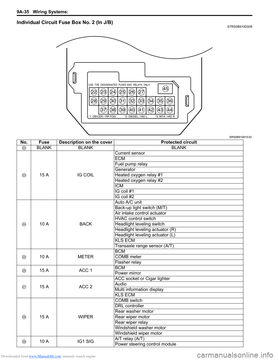
Individual Circuit Fuse Box No. 2 (In J/B)S7RS0B910D006
22
28
23
29
37
24
30
38
25
31
39
26
32
40
27
33
41
34
42
35
43
36
44
45USE THE DESINGNATED FUSES AND RELAYS ONLY.
*1: DEICER / RR FOG *2: DIESEL / HID L *3: MTA / HID R
I5RS0B910919-02
No. Fuse Description on the coverProtected circuit
BLANK BLANK BLANK
15 A IG COILCurrent sensor
ECM
Fuel pump relay
Generator
Heated oxygen relay #1
Heated oxygen relay #2
ICM
IG coil #1
IG coil #2
10 A BACKAuto A/C unit
Back-up light switch (M/T)
Air intake control actuator
HVAC control switch
Headlight leveling switch
Headlight leveling actuator (R)
Headlight leveling actuator (L)
KLS ECM
Transaxle range sensor (A/T)
10 A METERBCM
COMB meter
Flasher relay
15 A ACC 1BCM
Power mirror
15 A ACC 2ACC socket or Cigar lighter
Audio
Multi information display
KLS ECM
15 A WIPERCOMB switch
DRL controller
Rear washer motor
Rear wiper motor
Rear wiper relay
Windshield washer motor
Windshield wiper motor
10 A IG1 SIGA/T relay (A/T)
Power steering control module
Page 1284 of 1496

Downloaded from www.Manualslib.com manuals search engine 9B-2 Lighting Systems:
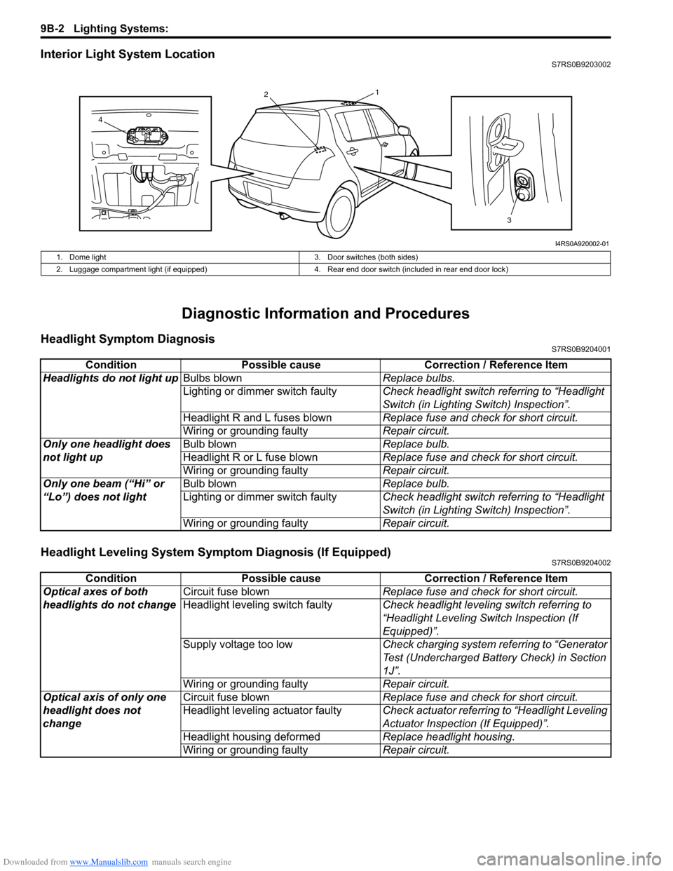
Interior Light System LocationS7RS0B9203002
Diagnostic Information and Procedures
Headlight Symptom DiagnosisS7RS0B9204001
Headlight Leveling System Symptom Diagnosis (If Equipped)S7RS0B9204002
13
2
4
I4RS0A920002-01
1. Dome light 3. Door switches (both sides)
2. Luggage compartment light (if equipped) 4. Rear end door switch (included in rear end door lock)
ConditionPossible cause Correction / Reference Item
Headlights do not light up Bulbs blown Replace bulbs.
Lighting or dimmer switch faulty Check headlight switch referring to “Headlight
Switch (in Lighting Switch) Inspection”.
Headlight R and L fuses blown Replace fuse and check for short circuit.
Wiring or grounding faulty Repair circuit.
Only one headlight does
not light up Bulb blown
Replace bulb.
Headlight R or L fuse blown Replace fuse and check for short circuit.
Wiring or grounding faulty Repair circuit.
Only one beam (“Hi” or
“Lo”) does not light Bulb blown
Replace bulb.
Lighting or dimmer switch faulty Check headlight switch referring to “Headlight
Switch (in Lighting Switch) Inspection”.
Wiring or grounding faulty Repair circuit.
ConditionPossible cause Correction / Reference Item
Optical axes of both
headlights do not change Circuit fuse blown
Replace fuse and check for short circuit.
Headlight leveling switch faulty Check headlight leveling switch referring to
“Headlight Leveling Switch Inspection (If
Equipped)”.
Supply voltage too low Check charging system referring to “Generator
Test (Undercharged Battery Check) in Section
1J”.
Wiring or grounding faulty Repair circuit.
Optical axis of only one
headlight does not
change Circuit fuse blown
Replace fuse and check for short circuit.
Headlight leveling actuator faulty Check actuator referring to “Headlight Leveling
Actuator Inspection (If Equipped)”.
Headlight housing deformed Replace headlight housing.
Wiring or grounding faulty Repair circuit.
Page 1419 of 1496
Downloaded from www.Manualslib.com manuals search engine Body Electrical Control System: 10B-16
BCM Power Circuit and Ground Circuit CheckS7RS0BA204007
Wiring Diagram
Troubleshooting
I4RS0AA20008-01
[A]: Junction block assembly connector viewed from harness side3. Ignition switch
1. BCM 4. Battery
2. Junction block assembly
Step Action YesNo
1 Fuse check
1) Turn ignition switch to OFF position.
2) Check circuit fuses for condition.
Are circuit fuses in good condition? Go to Step 2.
Replace fuse and check
for short circuit to
ground.
2 Power supply circuit check
1) Disconnect connectors from junction block assembly.
2) Check for proper connection to junction block assembly
connector at terminal “E40-2”.
3) If OK, then measure voltage between “E40-2” terminal of junction block assembly connector and vehicle body
ground.
Is voltage 10 – 14 V? Go to Step 3.
Repair power supply
circuit.
Page 1484 of 1496

Downloaded from www.Manualslib.com manuals search engine 10E-22 Keyless Start System:
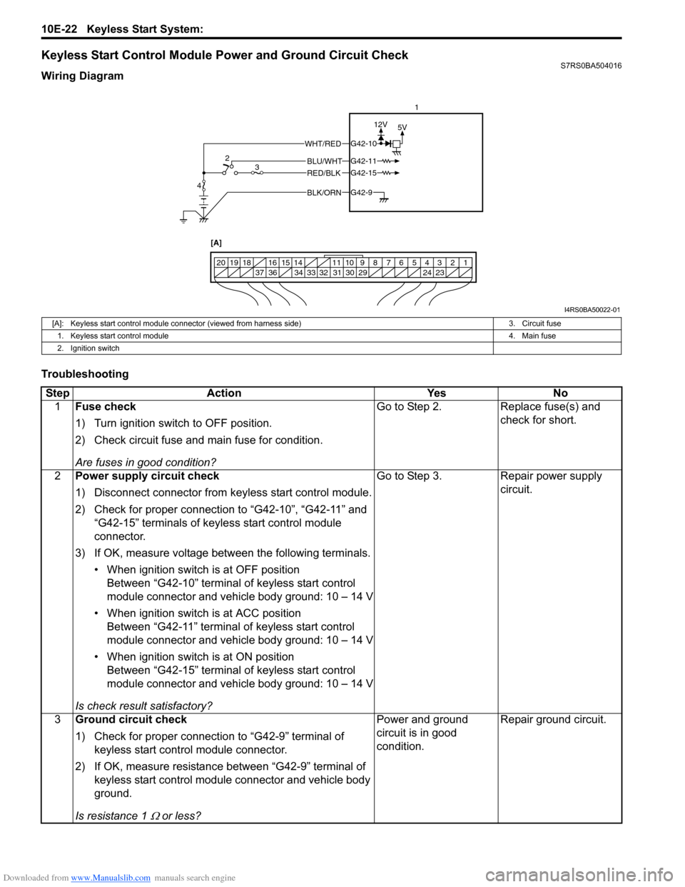
Keyless Start Control Module Power and Ground Circuit CheckS7RS0BA504016
Wiring Diagram
Troubleshooting
BLK/ORNG42-9
G42-15
G42-10
G42-11BLU/WHT
WHT/RED
RED/BLK
5V
12V
1234567891011
141516
36 34 33 32 31 30 29 24 23
37
181920
[A]
4 2
3 1
I4RS0BA50022-01
[A]: Keyless start control module connector (viewed from harness side)
3. Circuit fuse
1. Keyless start control module 4. Main fuse
2. Ignition switch
Step Action YesNo
1 Fuse check
1) Turn ignition switch to OFF position.
2) Check circuit fuse and main fuse for condition.
Are fuses in good condition? Go to Step 2.
Replace fuse(s) and
check for short.
2 Power supply circuit check
1) Disconnect connector from keyless start control module.
2) Check for proper connection to “G42-10”, “G42-11” and
“G42-15” terminals of keyless start control module
connector.
3) If OK, measure voltage between the following terminals. • When ignition switch is at OFF positionBetween “G42-10” terminal of keyless start control
module connector and vehicle body ground: 10 – 14 V
• When ignition switch is at ACC position Between “G42-11” terminal of keyless start control
module connector and vehicle body ground: 10 – 14 V
• When ignition switch is at ON position Between “G42-15” terminal of keyless start control
module connector and vehicle body ground: 10 – 14 V
Is check result satisfactory? Go to Step 3.
Repair power supply
circuit.
3 Ground circuit check
1) Check for proper connection to “G42-9” terminal of
keyless start control module connector.
2) If OK, measure resistance between “G42-9” terminal of keyless start control module connector and vehicle body
ground.
Is resistance 1
Ω or less? Power and ground
circuit is in good
condition.
Repair ground circuit.
Page:
< prev 1-8 9-16 17-24