2005 SUZUKI SWIFT Cleaning
[x] Cancel search: CleaningPage 815 of 1496
Downloaded from www.Manualslib.com manuals search engine Manual Transmission/Transaxle: 5B-1
Transmission / Transaxle
Manual Transmission/Transaxle
General Description
Manual Transaxle Construction and ServicingS7RS0B5201001
The transaxle provides five forward speeds and one reverse speed by means of three synchromeshs and three shafts
(input shaft, countershaft and reverse gear shaft). All forward gears are in constant mesh, and reverse uses a sliding
idler gear arrangement.
The low speed synchronizer sleeve & hub is mounted on countershaft and engaged with countershaft 1st gear or 2nd
gear, while the high speed synchronizer sleeve & hub is don e on input shaft and engaged with input shaft 3rd gear or
4th gear. The 5th speed synchronizer sleev e & hub on input shaft is engaged with input shaft fifth gear mounted on the
input shaft.
To prevent the cracking noise from the reverse gear when shifting transaxle gear into the reverse gear, the reverse
shift braking device is used.
The device utilizes the 5th synchromesh, which is the lever synchro type, to appl y the brake on the input shaft rotation.
The double cone synchronizing mechanism is provided to 2nd gear synchromesh device for high performance of
shifting to 2nd gear.
The countershaft turns the final gear and differential assembly, thereby turning the front drive shafts which are
attached to the front wheels.
For servicing, it is ne cessary to use genuine sealant or its equivalent on mating surfaces of transaxle case which is
made of aluminum. The case fastening bolts must be tight ened to specified torque by means of torque wrench. It is
also important that all parts are thoroughly cleaned with cleaning fluid and air dried before reassembling.
Further, care must be taken to adjust preload of count ershaft taper roller bearings. New synchronizer rings are
prohibited from being lapped with respective gear cones by using lapping compound before they are assembled.
Page 964 of 1496
Downloaded from www.Manualslib.com manuals search engine 7B-16 Air Conditioning System: Manual Type
Repair Instructions
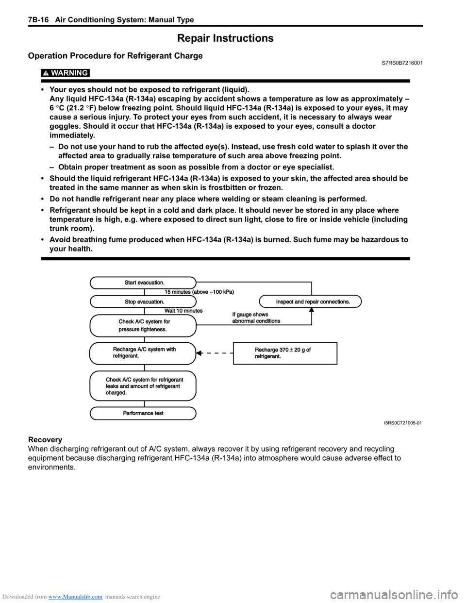
Operation Procedure for Refrigerant ChargeS7RS0B7216001
WARNING!
• Your eyes should not be exposed to refrigerant (liquid).Any liquid HFC-134a (R-134a) escaping by accident shows a temperature as low as approximately –
6 °C (21.2 ° F) below freezing point. Should liquid HFC-134a (R-134a) is exposed to your eyes, it may
cause a serious injury. To protect your eyes from such accident, it is necessary to always wear
goggles. Should it occur that HFC-134a (R-134a) is exposed to your eyes, consult a doctor
immediately.
– Do not use your hand to rub the affected eye(s). Instead, use fresh cold water to splash it over the affected area to gradually raise temperature of such area above freezing point.
– Obtain proper treatment as soon as possible from a doctor or eye specialist.
• Should the liquid refrigerant HFC-134a (R-134a) is exposed to your skin, the affected area should be treated in the same manner as when skin is frostbitten or frozen.
• Do not handle refrigerant near any place where welding or steam cleaning is performed.
• Refrigerant should be kept in a cold and dark pl ace. It should never be stored in any place where
temperature is high, e.g. where exposed to direct su n light, close to fire or inside vehicle (including
trunk room).
• Avoid breathing fume produced when HFC-134a (R-134a) is burned. Such fume may be hazardous to your health.
Recovery
When discharging refrigerant out of A/C system, always recover it by using refrigerant recovery and recycling
equipment because discharging refrigerant HFC-134a (R-1 34a) into atmosphere would cause adverse effect to
environments.
Start evacuation.Start evacuation.
Stop evacuation.Stop evacuation.
Wait 10 minutesWait 10 minutes
Check A/C system forCheck A/C system for
pressure tighteness.pressure tighteness.
Recharge A/C system withRecharge A/C system withrefrigerant.refrigerant.
Check A/C system for refrigerantCheck A/C system for refrigerantleaks and amount of refrigerantleaks and amount of refrigerantcharged.charged.
Performance testPerformance test
Inspect and repair connections.Inspect and repair connections.
If gauge showsIf gauge showsabnormal conditionsabnormal conditions
Recharge 370 20 g ofRecharge 370 20 g ofrefrigerant.refrigerant.
I5RS0C721005-01
Page 1041 of 1496
Downloaded from www.Manualslib.com manuals search engine Air Bag System: 8B-3
• Never attempt disassembly of the air bag (inflator) modules.
• If any abnormality is found, be sure to replace it with
new one as an assembly.
• When an abnormality is noted as existing in the live (undeployed) air bag (inflator) module, be sure to
deploy it before discarding it.
• When grease, cleaning agent, oil, water, etc., got on the air bag (inflator) modules (driver, passenger, side
of both sides and curtain of both sides), wipe it off
immediately with a dry cloth.
• If air bag (inflator) module was dropped from a height of 90 cm (3 ft) or more, it should be replaced with a
new one as an assembly.
WARNING!
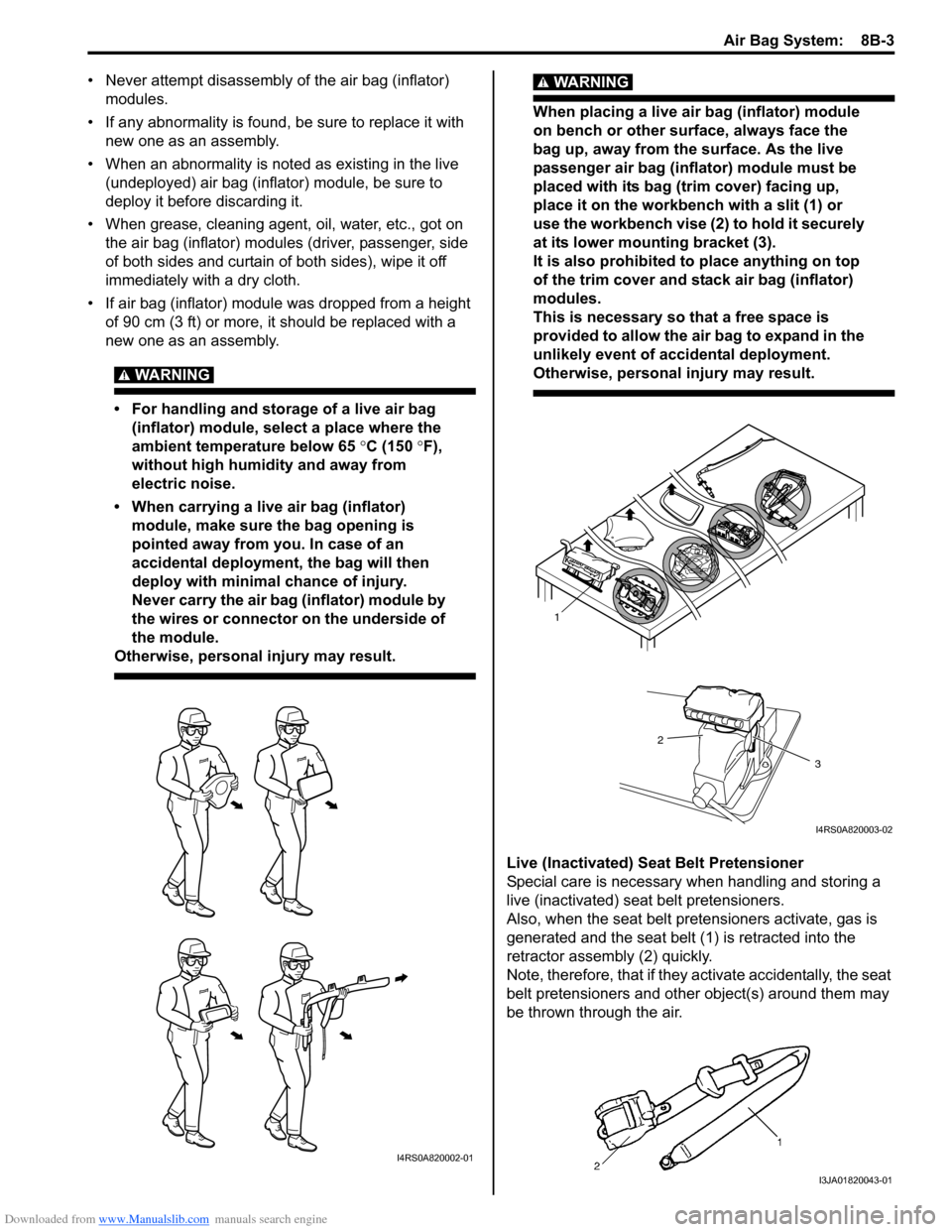
• For handling and storage of a live air bag (inflator) module, select a place where the
ambient temperature below 65 °C (150 ° F),
without high humidity and away from
electric noise.
• When carrying a live air bag (inflator) module, make sure the bag opening is
pointed away from you. In case of an
accidental deployment, the bag will then
deploy with minimal chance of injury.
Never carry the air bag (inflator) module by
the wires or connector on the underside of
the module.
Otherwise, personal injury may result.
WARNING!
When placing a live air bag (inflator) module
on bench or other surface, always face the
bag up, away from the surface. As the live
passenger air bag (inflator) module must be
placed with its bag (trim cover) facing up,
place it on the workbench with a slit (1) or
use the workbench vise (2) to hold it securely
at its lower mounting bracket (3).
It is also prohibited to place anything on top
of the trim cover and stack air bag (inflator)
modules.
This is necessary so that a free space is
provided to allow the air bag to expand in the
unlikely event of accidental deployment.
Otherwise, personal injury may result.
Live (Inactivated) Seat Belt Pretensioner
Special care is necessary when handling and storing a
live (inactivated) seat belt pretensioners.
Also, when the seat belt pretensioners activate, gas is
generated and the seat belt (1) is retracted into the
retractor assembly (2) quickly.
Note, therefore, that if they activate accidentally, the seat
belt pretensioners and other object(s) around them may
be thrown through the air.
I4RS0A820002-01
1
2
3
I4RS0A820003-02
I3JA01820043-01
Page 1042 of 1496
Downloaded from www.Manualslib.com manuals search engine 8B-4 Air Bag System:
WARNING!
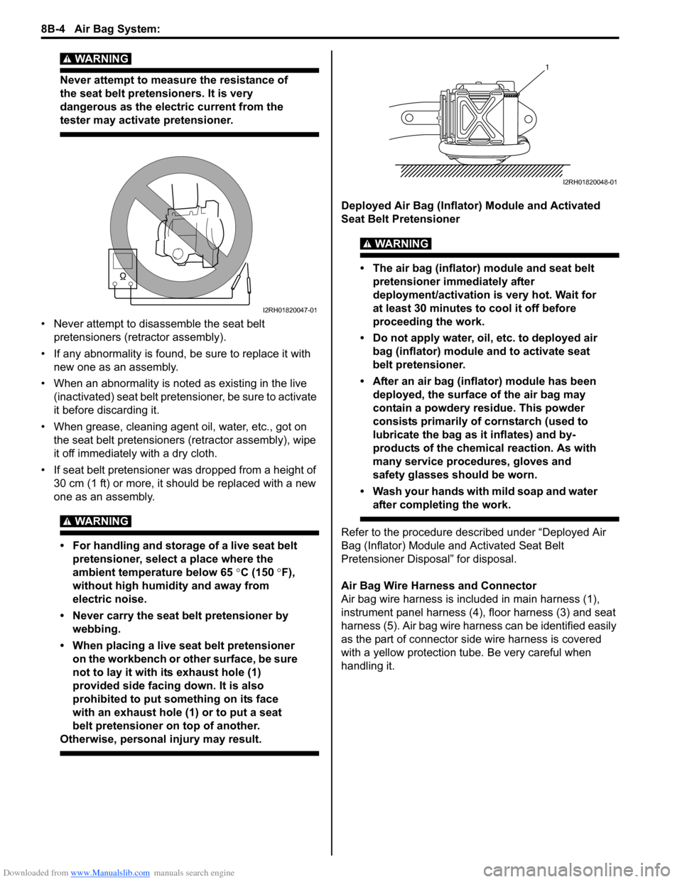
Never attempt to measure the resistance of
the seat belt pretensioners. It is very
dangerous as the electric current from the
tester may activate pretensioner.
• Never attempt to disassemble the seat belt
pretensioners (retractor assembly).
• If any abnormality is found, be sure to replace it with
new one as an assembly.
• When an abnormality is noted as existing in the live (inactivated) seat belt preten sioner, be sure to activate
it before discarding it.
• When grease, cleaning agent oil, water, etc., got on the seat belt pretensioners (r etractor assembly), wipe
it off immediately with a dry cloth.
• If seat belt pretensioner was dropped from a height of 30 cm (1 ft) or more, it should be replaced with a new
one as an assembly.
WARNING!
• For handling and storage of a live seat belt pretensioner, select a place where the
ambient temperature below 65 °C (150 ° F),
without high humidity and away from
electric noise.
• Never carry the seat belt pretensioner by webbing.
• When placing a live seat belt pretensioner on the workbench or other surface, be sure
not to lay it with its exhaust hole (1)
provided side facing down. It is also
prohibited to put something on its face
with an exhaust hole (1) or to put a seat
belt pretensioner on top of another.
Otherwise, personal injury may result.
Deployed Air Bag (Inflator) Module and Activated
Seat Belt Pretensioner
WARNING!
• The air bag (inflator) module and seat belt
pretensioner immediately after
deployment/activation is very hot. Wait for
at least 30 minutes to cool it off before
proceeding the work.
• Do not apply water, oil, etc. to deployed air bag (inflator) module and to activate seat
belt pretensioner.
• After an air bag (inflator) module has been deployed, the surface of the air bag may
contain a powdery residue. This powder
consists primarily of cornstarch (used to
lubricate the bag as it inflates) and by-
products of the chemical reaction. As with
many service procedures, gloves and
safety glasses should be worn.
• Wash your hands with mild soap and water after completing the work.
Refer to the procedure described under “Deployed Air
Bag (Inflator) Module and Activated Seat Belt
Pretensioner Disposal” for disposal.
Air Bag Wire Harness and Connector
Air bag wire harness is includ ed in main harness (1),
instrument panel harness (4), floor harness (3) and seat
harness (5). Air bag wire harness can be identified easily
as the part of connector side wire harness is covered
with a yellow protection tube. Be very careful when
handling it.
I2RH01820047-01
1
I2RH01820048-01
Page 1133 of 1496
Downloaded from www.Manualslib.com manuals search engine Air Bag System: 8B-95
Inspection of Intermittent and Poor
Connections
S7RS0B8204048
Most intermittents are caused by faulty electrical
connections or wiring. When a check for proper
connection is requested in a diagnostic flow, perform
careful check of suspect circuits.
If any abnormality is found, repair or replace as a wire
harness assembly.
• Poor mating of connector halves, or terminals not fully seated in the connector body (backed out).
• Dirt or corrosion on the terminals. The terminals must be clean and free of any foreign material which could
impede proper terminal contact.
However, cleaning the terminal with a sand paper or
the like is prohibited.
• Damaged connector body, exposing the terminals to moisture and dirt, as well as not maintaining proper
terminal orientation with the component or mating
connector.
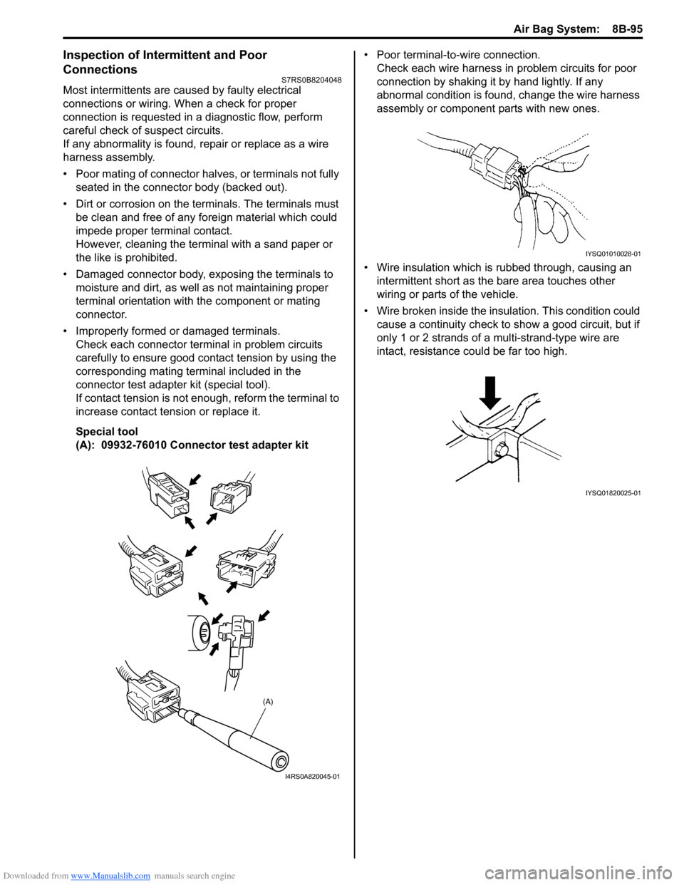
• Improperly formed or damaged terminals. Check each connector terminal in problem circuits
carefully to ensure good contact tension by using the
corresponding mating terminal included in the
connector test adapter kit (special tool).
If contact tension is not e nough, reform the terminal to
increase contact tension or replace it.
Special tool
(A): 09932-76010 Connector test adapter kit • Poor terminal-to-wire connection.
Check each wire harness in problem circuits for poor
connection by shaking it by hand lightly. If any
abnormal condition is found, change the wire harness
assembly or component parts with new ones.
• Wire insulation which is rubbed through, causing an intermittent short as the bare area touches other
wiring or parts of the vehicle.
• Wire broken inside the insulation. This condition could cause a continuity check to show a good circuit, but if
only 1 or 2 strands of a multi-strand-type wire are
intact, resistance could be far too high.
(A)
I4RS0A820045-01
IYSQ01010028-01
IYSQ01820025-01
Page 1332 of 1496
Downloaded from www.Manualslib.com manuals search engine 9E-5 Glass / Windows / Mirrors:
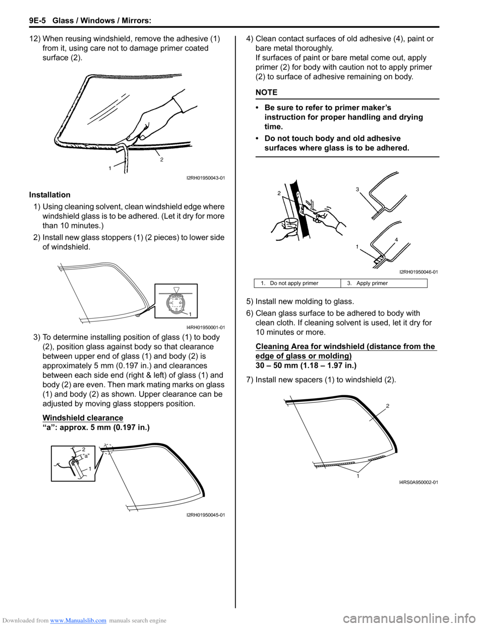
12) When reusing windshield, remove the adhesive (1) from it, using care not to damage primer coated
surface (2).
Installation 1) Using cleaning solvent, clean windshield edge where windshield glass is to be adhered. (Let it dry for more
than 10 minutes.)
2) Install new glass stoppers (1) (2 pieces) to lower side of windshield.
3) To determine installing position of glass (1) to body (2), position glass against body so that clearance
between upper end of glass (1) and body (2) is
approximately 5 mm (0.197 in.) and clearances
between each side end (right & left) of glass (1) and
body (2) are even. Then mark mating marks on glass
(1) and body (2) as shown. Upper clearance can be
adjusted by moving glass stoppers position.
Windshield clearance
“a”: approx. 5 mm (0.197 in.) 4) Clean contact surfaces of old adhesive (4), paint or
bare metal thoroughly.
If surfaces of paint or ba re metal come out, apply
primer (2) for body with caution not to apply primer
(2) to surface of adhesive remaining on body.
NOTE
• Be sure to refer to primer maker’s instruction for proper handling and drying
time.
• Do not touch body and old adhesive surfaces where glass is to be adhered.
5) Install new molding to glass.
6) Clean glass surface to be adhered to body with clean cloth. If cleaning solvent is used, let it dry for
10 minutes or more.
Cleaning Area for windshie ld (distance from the
edge of glass or molding)
30 – 50 mm (1.18 – 1.97 in.)
7) Install new spacers (1) to windshield (2).
I2RH01950043-01
1
I4RH01950001-01
2
1“a”
I2RH01950045-01
1. Do not apply primer 3. Apply primer
I2RH01950046-01
2
1I4RS0A950002-01
Page 1342 of 1496
Downloaded from www.Manualslib.com manuals search engine 9E-15 Glass / Windows / Mirrors:
Rear End Door Window Defogger Wire
Inspection
S7RS0B9506014
NOTE
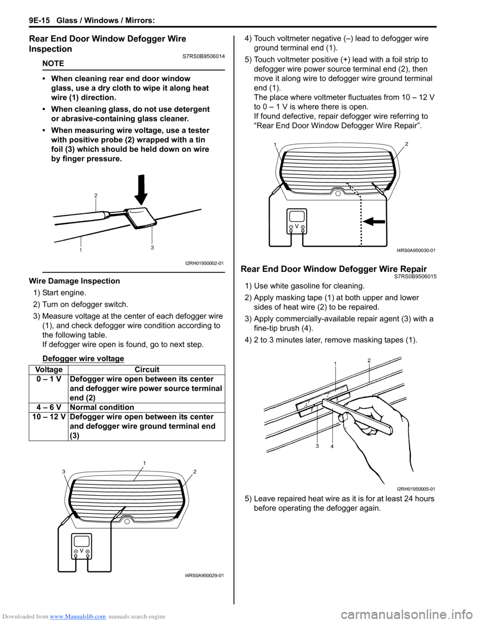
• When cleaning rear end door window glass, use a dry cloth to wipe it along heat
wire (1) direction.
• When cleaning glass, do not use detergent or abrasive-containing glass cleaner.
• When measuring wire voltage, use a tester with positive probe (2) wrapped with a tin
foil (3) which should be held down on wire
by finger pressure.
Wire Damage Inspection
1) Start engine.
2) Turn on defogger switch.
3) Measure voltage at the center of each defogger wire (1), and check defogger wire condition according to
the following table.
If defogger wire open is found, go to next step.
Defogger wire voltage
4) Touch voltmeter negative (–) lead to defogger wire ground terminal end (1).
5) Touch voltmeter positive (+) lead with a foil strip to defogger wire power source terminal end (2), then
move it along wire to defogger wire ground terminal
end (1).
The place where voltmeter fluctuates from 10 – 12 V
to 0 – 1 V is where there is open.
If found defective, repair defogger wire referring to
“Rear End Door Window Defogger Wire Repair”.
Rear End Door Window Defogger Wire RepairS7RS0B9506015
1) Use white gasoline for cleaning.
2) Apply masking tape (1) at both upper and lower sides of heat wire (2) to be repaired.
3) Apply commercially-available repair agent (3) with a fine-tip brush (4).
4) 2 to 3 minutes later, remove masking tapes (1).
5) Leave repaired heat wire as it is for at least 24 hours before operating the defogger again.
Voltage Circuit
0 – 1 V Defogger wire open between its center and defogger wire power source terminal
end (2)
4 – 6 V Normal condition
10 – 12 V Defogger wire open between its center and defogger wire ground terminal end
(3)
I2RH01950002-01
2
1
3
I4RS0A950029-01
21
I4RS0A950030-01
I2RH01950005-01
Page 1389 of 1496
Downloaded from www.Manualslib.com manuals search engine Paint / Coatings: 9L-2
Plastic Parts FinishingS7RS0B9C01002
Paintable plastic parts are ABS plastic parts.
Painting
Rigid or hand ABS plastic needs no primer coating.
General acrylic lacquers can be painted properly over hard ABS plastic in terms of adherence.
1) Use cleaning solvent for paint finish to wash each part.
2) Apply conventional acrylic color lacquer to part surface.
3) Follow lacquer directions for required drying time. (Proper drying temperature range is 60 – 70 °C (140 – 158 ° F)).
Reference
Plastic parts employ not only ABS (Acrylonitrile Butadiene Styrene) plastic but also polypro pylene, vinyl, or the like
plastic. Burning test method to iden tify ABS plastic is described below.
1) Use a sharp blade to cut off a plastic sliver from the part at its hidden backside.
2) Hold sliver with pincer s and set it on fire.
3) Carefully observe condition of the burning plastic.
4) ABS plastic must raise readily dist inguishable back smoke while burning with its residue suspended in air
temporarily.
5) Polypropylene must raise no readily distinguishable smoke while burning.