2005 SUZUKI SWIFT power
[x] Cancel search: powerPage 1000 of 1496
Downloaded from www.Manualslib.com manuals search engine 7B-52 Air Conditioning System: Automatic Type
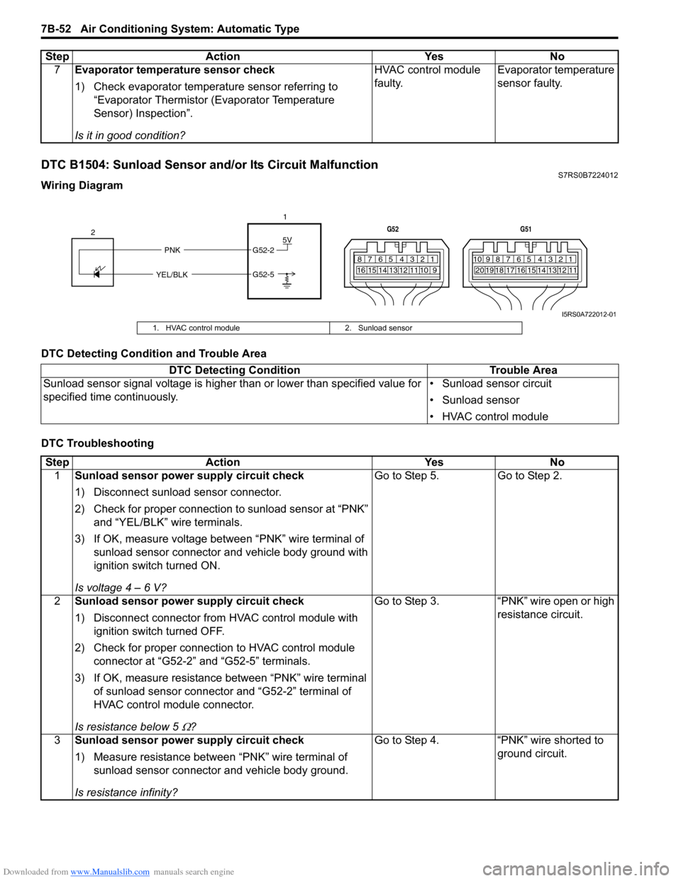
DTC B1504: Sunload Sensor and/or Its Circuit MalfunctionS7RS0B7224012
Wiring Diagram
DTC Detecting Condition and Trouble Area
DTC Troubleshooting7
Evaporator temperature sensor check
1) Check evaporator temperature sensor referring to
“Evaporator Thermistor (Evaporator Temperature
Sensor) Inspection”.
Is it in good condition? HVAC control module
faulty.
Evaporator temperature
sensor faulty.
Step Action Yes No
5V
PNK G52-2
G52-5
YEL/BLK
2
1
7812910
65 431516 14 13 12 11
G52
789101920121112
65 431718 16 15 14 13
G51
I5RS0A722012-01
1. HVAC control module
2. Sunload sensor
DTC Detecting Condition Trouble Area
Sunload sensor signal voltage is higher than or lower than specified value for
specified time continuously. • Sunload sensor circuit
• Sunload sensor
• HVAC control module
Step
Action YesNo
1 Sunload sensor power supply circuit check
1) Disconnect sunload sensor connector.
2) Check for proper connection to sunload sensor at “PNK”
and “YEL/BLK” wire terminals.
3) If OK, measure voltage between “PNK” wire terminal of sunload sensor connector and vehicle body ground with
ignition switch turned ON.
Is voltage 4 – 6 V? Go to Step 5.
Go to Step 2.
2 Sunload sensor power supply circuit check
1) Disconnect connector from HVAC control module with
ignition switch turned OFF.
2) Check for proper connection to HVAC control module connector at “G52-2” and “G52-5” terminals.
3) If OK, measure resistance between “PNK” wire terminal of sunload sensor connector and “G52-2” terminal of
HVAC control module connector.
Is resistance below 5
Ω? Go to Step 3. “PNK” wire open or high
resistance circuit.
3 Sunload sensor power supply circuit check
1) Measure resistance between “PNK” wire terminal of
sunload sensor connector and vehicle body ground.
Is resistance infinity? Go to Step 4. “PNK” wire shorted to
ground circuit.
Page 1001 of 1496
Downloaded from www.Manualslib.com manuals search engine Air Conditioning System: Automatic Type 7B-53
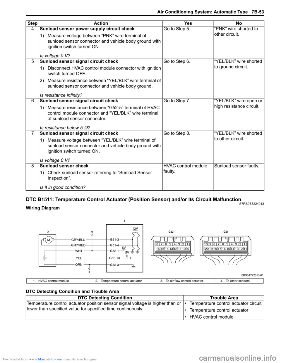
DTC B1511: Temperature Control Actuator (Position Sensor) and/or Its Circuit MalfunctionS7RS0B7224013
Wiring Diagram
DTC Detecting Condition and Trouble Area4
Sunload sensor power supply circuit check
1) Measure voltage between “PNK” wire terminal of
sunload sensor connector and vehicle body ground with
ignition switch turned ON.
Is voltage 0 V? Go to Step 5. “PNK” wire shorted to
other circuit.
5 Sunload sensor signal circuit check
1) Disconnect HVAC control modul e connector with ignition
switch turned OFF.
2) Measure resistance between “YEL/BLK” wire terminal of sunload sensor connector and vehicle body ground.
Is resistance infinity? Go to Step 6. “YEL/BLK” wire shorted
to ground circuit.
6 Sunload sensor signal circuit check
1) Measure resistance between “G52-5” terminal of HVAC
control module connector and “YEL/BLK” wire terminal
of sunload sensor connector.
Is resistance below 5
Ω? Go to Step 7. “YEL/BLK” wire open or
high resistance circuit.
7 Sunload sensor signal circuit check
1) Measure voltage between “YEL/BLK” wire terminal of
sunload sensor connector and vehicle body ground with
ignition switch turned ON.
Is voltage 0 V? Go to Step 8.
“YEL/BLK” wire shorted
to other circuit.
8 Sunload sensor check
1) Check sunload sensor referring to “Sunload Sensor
Inspection”.
Is it in good condition? HVAC control module
faulty.
Sunload sensor faulty.
Step
Action YesNo
7812910
65 431516 14 13 12 11
G52
789101920121112
65 431718 16 15 14 13
G51
M 12V
5V 5V
YEL
WHT
GRY/BLU
GRY/RED
2
1
ORN
G51-3
G51-4
G52-1
G52-13
G52-3
3
4
I5RS0A722013-01
1. HVAC control module 2. Temperature control actuator 3. To air flow control actuator4. To other sensors
DTC Detecting Condition Trouble Area
Temperature control actuator position sensor signal voltage is higher than or
lower than specified value for specified time continuously. • Temperature control actuator circuit
• Temperature control actuator
• HVAC control module
Page 1002 of 1496
Downloaded from www.Manualslib.com manuals search engine 7B-54 Air Conditioning System: Automatic Type
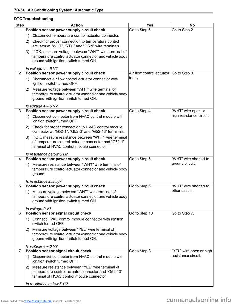
DTC TroubleshootingStep Action YesNo
1 Position sensor power supply circuit check
1) Disconnect temperature control actuator connector.
2) Check for proper connection to temperature control
actuator at “WHT”, “YEL” and “ORN” wire terminals.
3) If OK, measure voltage between “WHT” wire terminal of temperature control actuator connector and vehicle body
ground with ignition switch turned ON.
Is voltage 4 – 6 V? Go to Step 6.
Go to Step 2.
2 Position sensor power supply circuit check
1) Disconnect air flow control actuator connector with
ignition switch turned OFF.
2) Measure voltage between “WHT” wire terminal of temperature control actuator connector and vehicle body
ground with ignition switch turned ON.
Is voltage 4 – 6 V? Air flow control actuator
faulty.
Go to Step 3.
3 Position sensor power supply circuit check
1) Disconnect connector from HVAC control module with
ignition switch turned OFF.
2) Check for proper connection to HVAC control module connector at “G52-1”, “G52-3” and “G52-13” terminals.
3) If OK, measure resistance between “WHT” wire terminal of temperature control actuator connector and “G52-1”
terminal of HVAC control module connector.
Is resistance below 5
Ω? Go to Step 4. “WHT” wire open or
high resistance circuit.
4 Position sensor power supply circuit check
1) Measure resistance between “WHT” wire terminal of
temperature control actuator connector and vehicle body
ground.
Is resistance infinity? Go to Step 5.
“WHT” wire shorted to
ground circuit.
5 Position sensor power supply circuit check
1) Measure voltage between “WHT” wire terminal of
temperature control actuator connector and vehicle body
ground with ignition switch turned ON.
Is voltage 0 V? Go to Step 6.
“WHT” wire shorted to
other circuit.
6 Position sensor signal circuit check
1) Connect HVAC control module connector with ignition
switch turned OFF.
2) Measure voltage between “YEL” wire terminal of temperature control actuator connector and vehicle body
ground with ignition switch turned ON.
Is voltage 4 – 6 V? Go to Step 10. Go to Step 7.
7 Position sensor signal circuit check
1) Disconnect connector from HVAC control module with
ignition switch turned OFF.
2) Measure resistance between “YEL” wire terminal of temperature control actuator connector and “G52-13”
terminal of HVAC control module connector.
Is resistance below 5
Ω? Go to Step 8. “YEL” wire open or high
resistance circuit.
Page 1004 of 1496
Downloaded from www.Manualslib.com manuals search engine 7B-56 Air Conditioning System: Automatic Type
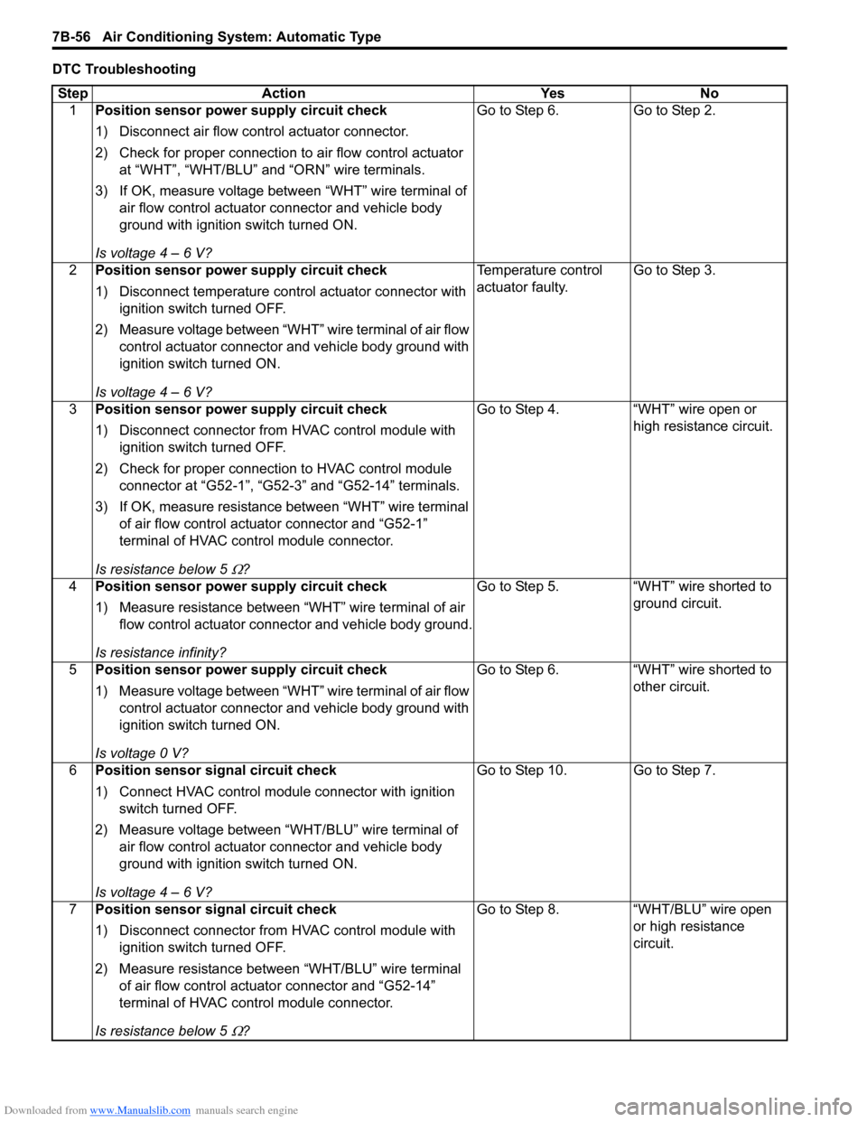
DTC TroubleshootingStep Action YesNo
1 Position sensor power supply circuit check
1) Disconnect air flow control actuator connector.
2) Check for proper connection to air flow control actuator
at “WHT”, “WHT/BLU” and “ORN” wire terminals.
3) If OK, measure voltage between “WHT” wire terminal of air flow control actuator connector and vehicle body
ground with ignition switch turned ON.
Is voltage 4 – 6 V? Go to Step 6.
Go to Step 2.
2 Position sensor power supply circuit check
1) Disconnect temperature control actuator connector with
ignition switch turned OFF.
2) Measure voltage between “WHT” wire terminal of air flow control actuator connector and vehicle body ground with
ignition switch turned ON.
Is voltage 4 – 6 V? Temperature control
actuator faulty.
Go to Step 3.
3 Position sensor power supply circuit check
1) Disconnect connector from HVAC control module with
ignition switch turned OFF.
2) Check for proper connection to HVAC control module connector at “G52-1”, “G52-3” and “G52-14” terminals.
3) If OK, measure resistance between “WHT” wire terminal of air flow control actuator connector and “G52-1”
terminal of HVAC control module connector.
Is resistance below 5
Ω? Go to Step 4. “WHT” wire open or
high resistance circuit.
4 Position sensor power supply circuit check
1) Measure resistance between “WHT” wire terminal of air
flow control actuator connector and vehicle body ground.
Is resistance infinity? Go to Step 5. “WHT” wire shorted to
ground circuit.
5 Position sensor power supply circuit check
1) Measure voltage between “WHT” wire terminal of air flow
control actuator connector and vehicle body ground with
ignition switch turned ON.
Is voltage 0 V? Go to Step 6. “WHT” wire shorted to
other circuit.
6 Position sensor signal circuit check
1) Connect HVAC control module connector with ignition
switch turned OFF.
2) Measure voltage between “WHT/BLU” wire terminal of air flow control actuator connector and vehicle body
ground with ignition switch turned ON.
Is voltage 4 – 6 V? Go to Step 10. Go to Step 7.
7 Position sensor signal circuit check
1) Disconnect connector from HVAC control module with
ignition switch turned OFF.
2) Measure resistance between “WHT/BLU” wire terminal of air flow control actuator connector and “G52-14”
terminal of HVAC control module connector.
Is resistance below 5
Ω? Go to Step 8. “WHT/BLU” wire open
or high resistance
circuit.
Page 1010 of 1496
Downloaded from www.Manualslib.com manuals search engine 7B-62 Air Conditioning System: Automatic Type
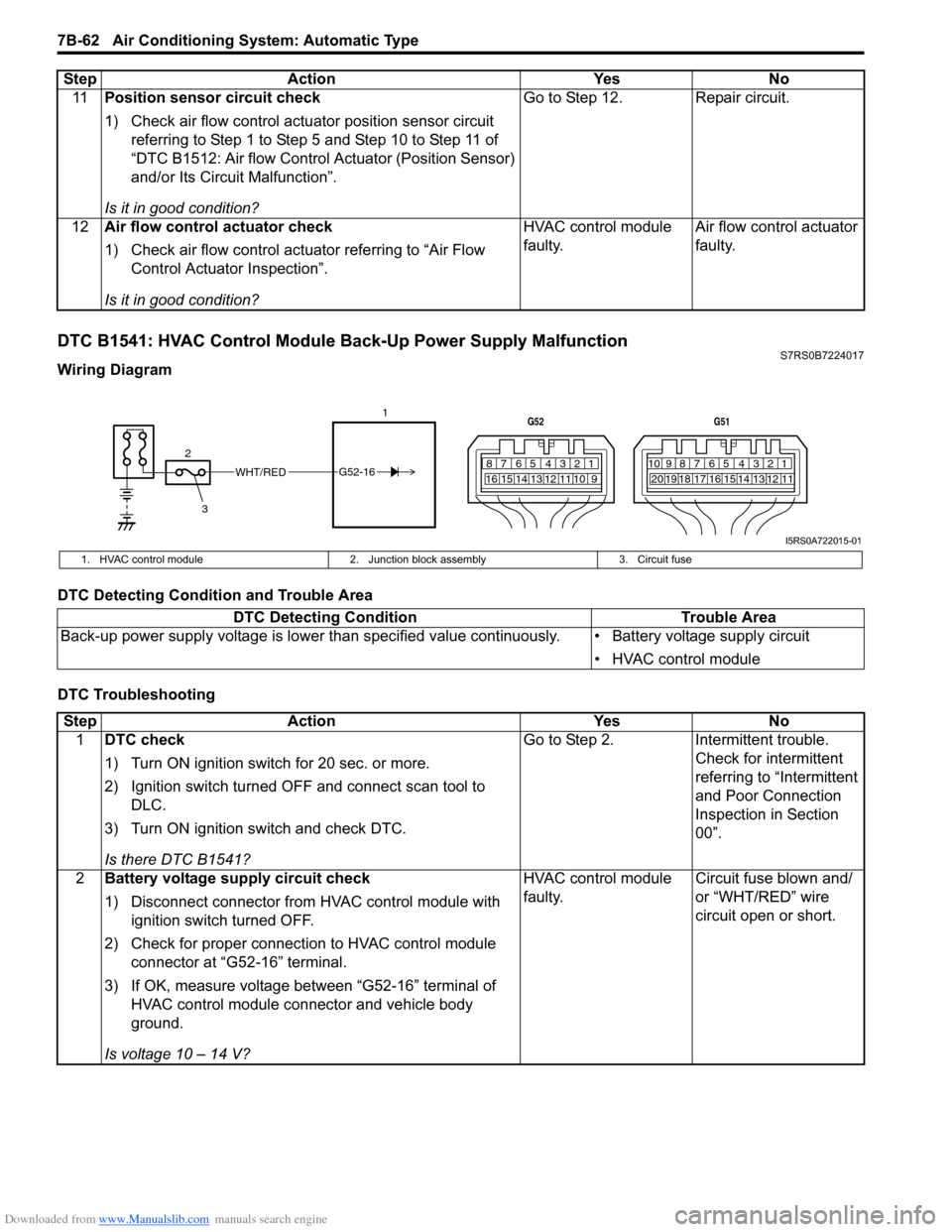
DTC B1541: HVAC Control Module Back-Up Power Supply MalfunctionS7RS0B7224017
Wiring Diagram
DTC Detecting Condition and Trouble Area
DTC Troubleshooting11
Position sensor circuit check
1) Check air flow control actuator position sensor circuit
referring to Step 1 to Step 5 and Step 10 to Step 11 of
“DTC B1512: Air flow Control Actuator (Position Sensor)
and/or Its Circuit Malfunction”.
Is it in good condition? Go to Step 12. Repair circuit.
12 Air flow control actuator check
1) Check air flow control actuator referring to “Air Flow
Control Actuator Inspection”.
Is it in good condition? HVAC control module
faulty.
Air flow control actuator
faulty.
Step Action Yes No
WHT/RED
2 17812910
65 431516 14 13 12 11
G52
789101920121112
65 431718 16 15 14 13
G51
3
G52-16
I5RS0A722015-01
1. HVAC control module
2. Junction block assembly 3. Circuit fuse
DTC Detecting Condition Trouble Area
Back-up power supply voltage is lo wer than specified value continuously. • Battery voltage supply circuit
• HVAC control module
StepAction YesNo
1 DTC check
1) Turn ON ignition switch for 20 sec. or more.
2) Ignition switch turned OF F and connect scan tool to
DLC.
3) Turn ON ignition switch and check DTC.
Is there DTC B1541? Go to Step 2.
Intermittent trouble.
Check for intermittent
referring to “Intermittent
and Poor Connection
Inspection in Section
00”.
2 Battery voltage supply circuit check
1) Disconnect connector from HVAC control module with
ignition switch turned OFF.
2) Check for proper connection to HVAC control module connector at “G52-16” terminal.
3) If OK, measure voltage between “G52-16” terminal of HVAC control module connector and vehicle body
ground.
Is voltage 10 – 14 V? HVAC control module
faulty.
Circuit fuse blown and/
or “WHT/RED” wire
circuit open or short.
Page 1017 of 1496
Downloaded from www.Manualslib.com manuals search engine Air Conditioning System: Automatic Type 7B-69
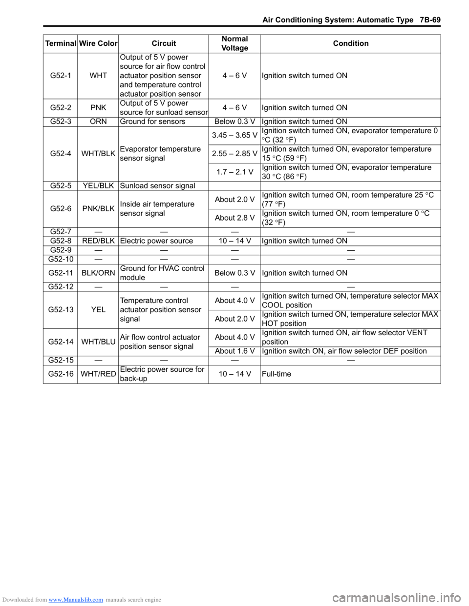
Terminal Wire Color CircuitNormal
Vo l ta g e Condition
G52-1 WHT Output of 5 V power
source for air flow control
actuator position sensor
and temperature control
actuator position sensor 4 – 6 V Ignition switch turned ON
G52-2 PNK Output of 5 V power
source for sunload sensor 4 – 6 V Ignition switch turned ON
G52-3 ORN Ground for sensors Below 0.3 V Ignition switch turned ON
G52-4 WHT/BLK Evaporator temperature
sensor signal 3.45 – 3.65 V
Ignition switch turned ON, evaporator temperature 0
°
C (32 °F)
2.55 – 2.85 V Ignition switch turned ON, evaporator temperature
15
°C (59 ° F)
1.7 – 2.1 V Ignition switch turned ON, evaporator temperature
30
°C (86 ° F)
G52-5 YEL/BLK Sunload sensor signal
G52-6 PNK/BLK Inside air temperature
sensor signal About 2.0 V
Ignition switch turned ON, room temperature 25
°C
(77 °F)
About 2.8 V Ignition switch turned ON, room temperature 0
°C
(32 °F)
G52-7 — — — —
G52-8 RED/BLK Electric power source 10 – 14 V Ignition switch turned ON
G52-9 — — — —
G52-10 — — — —
G52-11 BLK/ORN Ground for HVAC control
module Below 0.3 V Ignition
switch turned ON
G52-12 — — — —
G52-13 YEL Temperature control
actuator position sensor
signal About 4.0 V
Ignition switch turned ON, temperature selector MAX
COOL position
About 2.0 V Ignition switch turned ON, temperature selector MAX
HOT position
G52-14 WHT/BLU Air flow control actuator
position sensor signal About 4.0 V
Ignition switch turned ON
, air flow selector VENT
position
About 1.6 V Ignition switch ON, air flow selector DEF position
G52-15 — — — —
G52-16 WHT/RED Electric power source for
back-up 10 – 14 V Full-time
Page 1019 of 1496
Downloaded from www.Manualslib.com manuals search engine Air Conditioning System: Automatic Type 7B-71
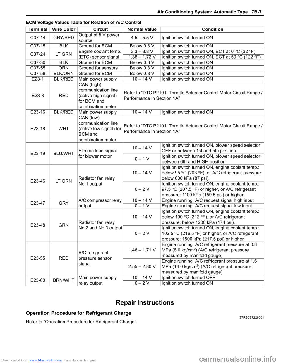
ECM Voltage Values Table for Relation of A/C Control
Repair Instructions
Operation Procedure for Refrigerant ChargeS7RS0B7226001
Refer to “Operation Procedure for Refrigerant Charge”.Terminal Wire Color Circuit Normal Value Condition
C37-14 GRY/RED Output of 5 V power
source 4.5 – 5.5 V Ignition switch turned ON
C37-15 BLK Ground for ECM Below 0.3 V Ignition switch turned ON
C37-24 LT GRN Engine coolant temp.
(ETC) sensor signal 3.3 – 3.8 V Ignition switch turned ON, ECT at 0
°C (32 ° F)
1.38 – 1.72 V Ignition switch turned ON, ECT at 50 °C (122 °F)
C37-30 BLK Ground for ECM Below 0.3 V Ignition switch turned ON
C37-55 ORN Ground for sensors Below 0.3 V Ignition switch turned ON
C37-58 BLK/ORN Ground for ECM Below 0.3 V Ignition switch turned ON E23-1 BLK/RED Main power supply 10 – 14 V Ignition switch turned ON
E23-3 RED CAN (high)
communication line
(active high signal)
for BCM and
combination meterRefer to “DTC P2101: Throttle Actu
ator Control Motor Circuit Range /
Performance in Section 1A”
E23-16 BLK/RED Main power supply 10 – 14 V Ignition switch turned ON
E23-18 WHT CAN (low)
communication line
(active low signal) for
BCM and
combination meterRefer to “DTC P2101: Throttle Actu
ator Control Motor Circuit Range /
Performance in Section 1A”
E23-19 BLU/WHT Electric load signal
for blower motor 10 – 14 V
Ignition switch turned ON, blower speed selector
OFF or between 1st and 5th position
0 – 1 V Ignition switch turned ON, blower speed selector
between 6th and HIGH position
E23-46 LT GRN Radiator fan relay
No.1 output 10 – 14 V
Ignition switch turned ON, engine coolant temp.:
below 95
°C (203 ° F), or A/C refrigerant pressure:
below 600 kPa (87 psi).
0 – 2 V Ignition switch turned ON, engine coolant temp.:
97.5
°C (207.5 °F) or higher, or A/C refrigerant
pressure: 1100 kPa (159.5 psi) or higher.
E23-47 GRY A/C compressor relay
output 10 – 14 V Engine running, A/C request signal high input
0 – 1 V Engine running, A/C request signal low input
E23-48 GRN Radiator fan relay
No.2 and No.3 output 10 – 14 V
Ignition switch turned ON, engine coolant temp.:
below 100
°C (212 °F), or A/C refrigerant
pressure: below 1200 kPa (174 psi).
0 – 2 V Ignition switch turned ON, engine coolant temp.:
102.5
°C (216.5 ° F) or higher, or A/C refrigerant
pressure: 1500 kPa (217.5 psi) or higher.
E23-55 RED A/C refrigerant
pressure sensor
signal 1.46 – 1.71 V
Engine running, A/C refrigerant pressure at 0.8
MPa (8.0 kg/cm
2) (A/C refrigerant pressure
measured by manifold gauge)
2.55 – 2.80 V Engine running, A/C refrigerant pressure at 1.6
MPa (16.0 kg/cm
2) (A/C refrigerant pressure
measured by manifold gauge)
E23-60 BRN/WHT Main power supply
relay output 10 – 14 V Ignition switch turned OFF
0 – 2 V Ignition switch turned ON
Page 1027 of 1496
Downloaded from www.Manualslib.com manuals search engine Air Conditioning System: Automatic Type 7B-79
Compressor Drive Belt Removal and
Installation
S7RS0B7226032
Refer to “Compressor Drive Belt Removal and
Installation”.
Compressor Assembly Removal and
Installation
S7RS0B7226033
Refer to “Compressor Assembly Removal and
Installation”.
Compressor Assembly ComponentsS7RS0B7226034
Refer to “Compressor Assembly Components”.
Magnet Clutch Removal and InstallationS7RS0B7226035
Refer to “Magnet Clutch Removal and Installation”.
Magnet Clutch InspectionS7RS0B7226036
Refer to “Magnet Clutch Inspection”.
Relief Valve InspectionS7RS0B7226039
Refer to “Relief Valve Inspection”.
Special Tools and Equipment
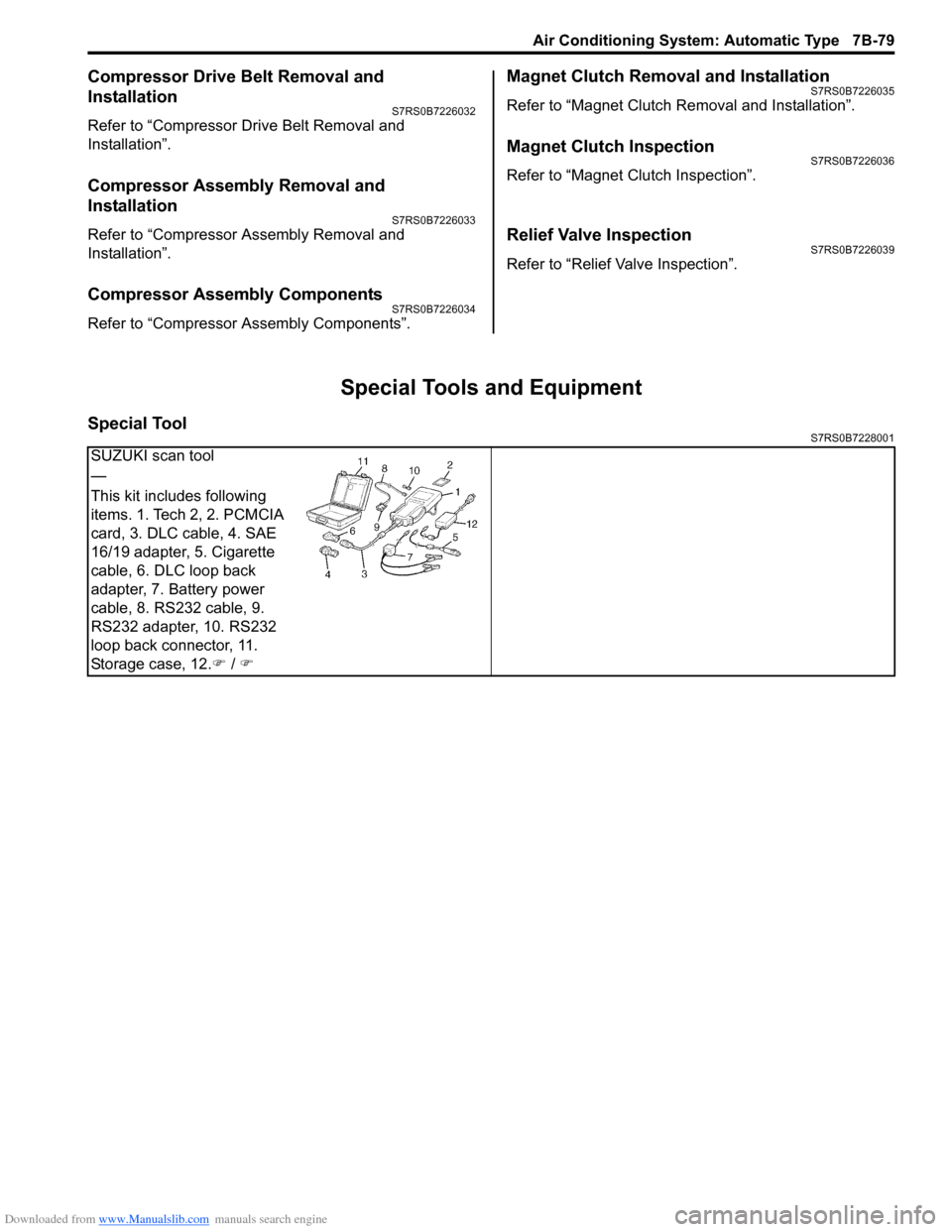
Special ToolS7RS0B7228001
SUZUKI scan tool
—
This kit includes following
items. 1. Tech 2, 2. PCMCIA
card, 3. DLC cable, 4. SAE
16/19 adapter, 5. Cigarette
cable, 6. DLC loop back
adapter, 7. Battery power
cable, 8. RS232 cable, 9.
RS232 adapter, 10. RS232
loop back connector, 11.
Storage case, 12.�) / �)