2005 SUZUKI SWIFT lock
[x] Cancel search: lockPage 801 of 1496
Downloaded from www.Manualslib.com manuals search engine Automatic Transmission/Transaxle: 5A-157
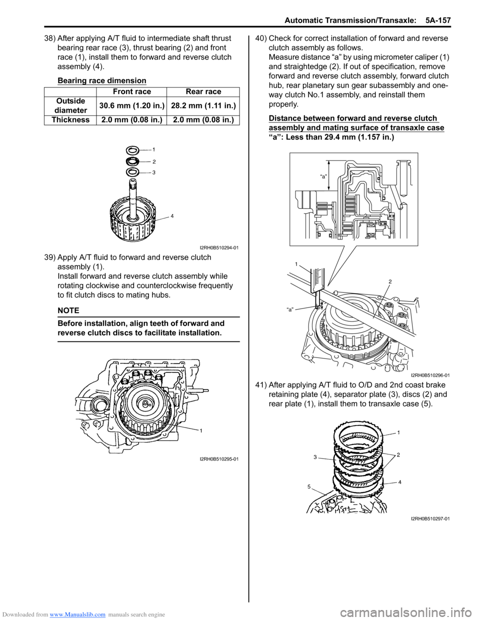
38) After applying A/T fluid to intermediate shaft thrust bearing rear race (3), thrust bearing (2) and front
race (1), install them to forward and reverse clutch
assembly (4).
Bearing race dimension
39) Apply A/T fluid to forward and reverse clutch assembly (1).
Install forward and revers e clutch assembly while
rotating clockwise and co unterclockwise frequently
to fit clutch discs to mating hubs.
NOTE
Before installation, align teeth of forward and
reverse clutch discs to facilitate installation.
40) Check for correct installation of forward and reverse clutch assembly as follows.
Measure distance “a” by using micrometer caliper (1)
and straightedge (2). If out of specification, remove
forward and reverse clutch assembly, forward clutch
hub, rear planetary sun gear subassembly and one-
way clutch No.1 assemb ly, and reinstall them
properly.
Distance between forward and reverse clutch
assembly and mating surface of transaxle case
“a”: Less than 29.4 mm (1.157 in.)
41) After applying A/T fluid to O/D and 2nd coast brake retaining plate (4), separator plate (3), discs (2) and
rear plate (1), install th em to transaxle case (5).
Front race Rear race
Outside
diameter 30.6 mm (1.20 in.) 28.2 mm (1.11 in.)
Thickness 2.0 mm (0.08 in.) 2.0 mm (0.08 in.)
I2RH0B510294-01
I2RH0B510295-01
“a”
“a”
1 2
I2RH0B510296-01
I2RH0B510297-01
Page 804 of 1496
Downloaded from www.Manualslib.com manuals search engine 5A-160 Automatic Transmission/Transaxle:
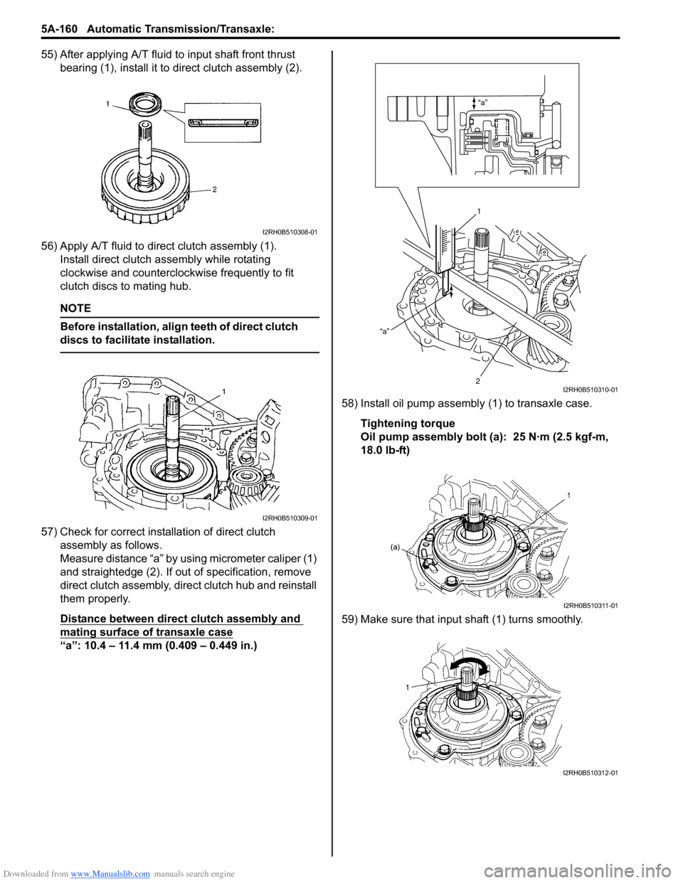
55) After applying A/T fluid to input shaft front thrust bearing (1), install it to direct clutch assembly (2).
56) Apply A/T fluid to direct clutch assembly (1). Install direct clutch a ssembly while rotating
clockwise and counterclockwise frequently to fit
clutch discs to mating hub.
NOTE
Before installation, align teeth of direct clutch
discs to facilitate installation.
57) Check for correct installation of direct clutch assembly as follows.
Measure distance “a” by using micrometer caliper (1)
and straightedge (2). If out of specification, remove
direct clutch assembly, direct clutch hub and reinstall
them properly.
Distance between direct clutch assembly and
mating surface of transaxle case
“a”: 10.4 – 11.4 mm (0.409 – 0.449 in.) 58) Install oil pump assembly
(1) to transaxle case.
Tightening torque
Oil pump assembly bolt (a): 25 N·m (2.5 kgf-m,
18.0 lb-ft)
59) Make sure that input shaft (1) turns smoothly.
I2RH0B510308-01
I2RH0B510309-01
“a”
“a”
1
2
I2RH0B510310-01
I2RH0B510311-01
I2RH0B510312-01
Page 809 of 1496
Downloaded from www.Manualslib.com manuals search engine Automatic Transmission/Transaxle: 5A-165
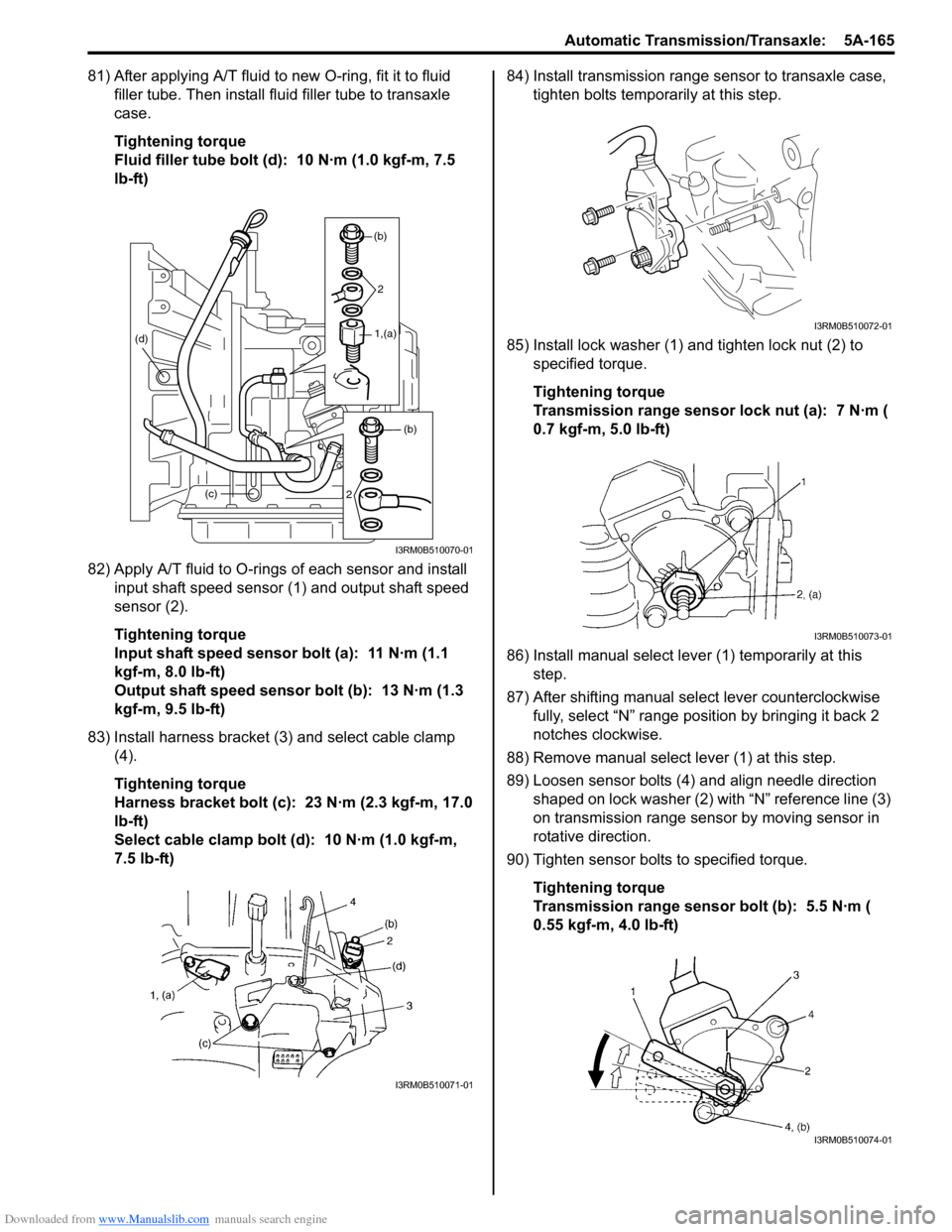
81) After applying A/T fluid to new O-ring, fit it to fluid filler tube. Then install fl uid filler tube to transaxle
case.
Tightening torque
Fluid filler tube bolt (d): 10 N·m (1.0 kgf-m, 7.5
lb-ft)
82) Apply A/T fluid to O-rings of each sensor and install input shaft speed sensor (1) and output shaft speed
sensor (2).
Tightening torque
Input shaft speed sensor bolt (a): 11 N·m (1.1
kgf-m, 8.0 lb-ft)
Output shaft speed sensor bolt (b): 13 N·m (1.3
kgf-m, 9.5 lb-ft)
83) Install harness bracket (3) and select cable clamp (4).
Tightening torque
Harness bracket bolt (c): 23 N·m (2.3 kgf-m, 17.0
lb-ft)
Select cable clamp bolt (d): 10 N·m (1.0 kgf-m,
7.5 lb-ft) 84) Install transmission range sensor to transaxle case,
tighten bolts temporarily at this step.
85) Install lock washer (1) and tighten lock nut (2) to specified torque.
Tightening torque
Transmission range sensor lock nut (a): 7 N·m (
0.7 kgf-m, 5.0 lb-ft)
86) Install manual select leve r (1) temporarily at this
step.
87) After shifting manual se lect lever counterclockwise
fully, select “N” range position by bringing it back 2
notches clockwise.
88) Remove manual select lever (1) at this step.
89) Loosen sensor bolts (4) and align needle direction shaped on lock washer (2) with “N” reference line (3)
on transmission range sensor by moving sensor in
rotative direction.
90) Tighten sensor bolts to specified torque.
Tightening torque
Transmission range sensor bolt (b): 5.5 N·m (
0.55 kgf-m, 4.0 lb-ft)
(c)
(d)
(b)
2
1,(a)
(b)
2
I3RM0B510070-01
I3RM0B510071-01
I3RM0B510072-01
I3RM0B510073-01
I3RM0B510074-01
Page 810 of 1496
Downloaded from www.Manualslib.com manuals search engine 5A-166 Automatic Transmission/Transaxle:
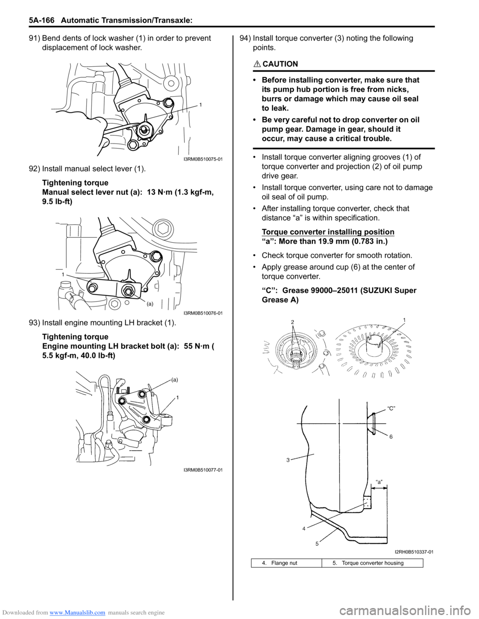
91) Bend dents of lock washer (1) in order to prevent displacement of lock washer.
92) Install manual select lever (1). Tightening torque
Manual select lever nut (a): 13 N·m (1.3 kgf-m,
9.5 lb-ft)
93) Install engine mounting LH bracket (1). Tightening torque
Engine mounting LH bracket bolt (a): 55 N·m (
5.5 kgf-m, 40.0 lb-ft) 94) Install torque converter (3) noting the following
points.
CAUTION!
• Before installing converter, make sure that its pump hub portion is free from nicks,
burrs or damage which may cause oil seal
to leak.
• Be very careful not to drop converter on oil pump gear. Damage in gear, should it
occur, may cause a critical trouble.
• Install torque converter aligning grooves (1) of torque converter and projection (2) of oil pump
drive gear.
• Install torque converter, using care not to damage oil seal of oil pump.
• After installing torque converter, check that distance “a” is within specification.
Torque converter installing position
“a”: More than 19.9 mm (0.783 in.)
• Check torque converter for smooth rotation.
• Apply grease around cup (6) at the center of torque converter.
“C”: Grease 99000–25011 (SUZUKI Super
Grease A)
1
I3RM0B510075-01
1
(a)
I3RM0B510076-01
I3RM0B510077-01
4. Flange nut 5. Torque converter housing
I2RH0B510337-01
Page 811 of 1496

Downloaded from www.Manualslib.com manuals search engine Automatic Transmission/Transaxle: 5A-167
Specifications
Tightening Torque SpecificationsS7RS0B5107001
NOTE
The specified tightening torque is also described in the following.
“Select Cable Components”
“Automatic Transaxle Unit Components”
“Automatic Transaxle Assembly Components”
“Oil Pump Assembly Components”
“Transaxle Rear Cover (O/D and 2nd Coast Brake Piston) Assembly Components”
“Valve Body Assembly Components”
“Differential Assembly Components”
Reference:
For the tightening torque of fastener not specified in this section, refer to “Fasteners Information in Section 0A”.
Fastening part
Tightening torque
Note
N ⋅mkgf-mlb-ft
A/T fluid drain plug 171.7 12.5 �) / �) / �)
Transmission range sensor bolt 5.5 0.55 4.0�) / �)
Output shaft speed sensor bolt 131.3 9.5 �) / �)
Input shaft speed sensor bolt 5.5 0.55 4.0�)
Valve body harness connector bolt 7.00.7 5.0 �)
Shift solenoid bolt 111.1 8.0 �)
Oil strainer bolt 101.0 7.5 �) / �)
Oil pan bolt 7.00.7 5.0 �) / �)
Transaxle and engine fastening bolt and nut 85 8.5 61.5�)
Drive plate to torque converter bolt 252.5 18.0 �)
Transaxle stiffener bolt 555.5 40�)
Starter motor bolt and nut 505.0 36.5 �)
Oil pump subassembly bolt 101.0 7.5 �)
Rear cover plug 7.5 0.75 5.5�)
Solenoid valve bolt 111.1 8.0 �)
Final gear bolt 787.8 56.5 �)
Torque converter housing plug 7.5 0.75 5.5�)
Lubrication tube clamp bolt 5.5 0.55 4.0�)
Fluid reservoir RH plate bolt 5.5 0.55 4.0�)
Torque converter housing bolt 292.9 21�) / �) / �)
Manual detent spring bolt 101.0 7.5 �)
Parking lock pawl bracket bolt 7.5 0.75 5.5�)
Rear cover bolt 252.5 18.0 �)
Fluid reservoir LH plate bolt 101.0 7.5 �)
Oil pump assembly bolt 252.5 18.0 �)
Transaxle case plug 7.5 0.75 5.5�)
Valve body harness connector bolt 5.5 0.55 4.0�)
Valve body bolt 111.1 8.0 �)
Fluid outlet union 252.5 18.0 �)
Fluid cooler pipe union bolt 222.2 16.0 �)
Fluid cooler pipe bracket bolt 101.0 7.5 �)
Fluid filler tube bolt 101.0 7.5 �)
Input shaft speed sensor bolt 111.1 8.0 �)
Harness bracket bolt 232.3 17.0 �)
Select cable clamp bolt 101.0 7.5 �)
Transmission range sensor lock nut 70.7 5.0 �)
Manual select lever nut 131.3 9.5 �)
Engine mounting LH bracket bolt 555.5 40.0
�)
Page 820 of 1496
Downloaded from www.Manualslib.com manuals search engine 5B-6 Manual Transmission/Transaxle:
Gear Shift Control Lever and Cable Removal
and Installation
S7RS0B5206004
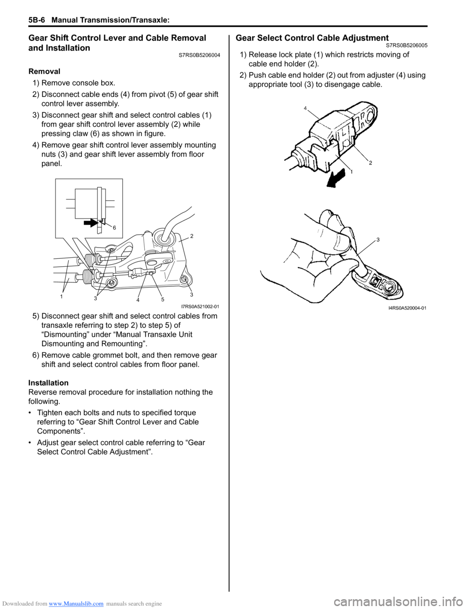
Removal1) Remove console box.
2) Disconnect cable ends (4) from pivot (5) of gear shift control lever assembly.
3) Disconnect gear shift and select control cables (1) from gear shift control lever assembly (2) while
pressing claw (6) as shown in figure.
4) Remove gear shift control lever assembly mounting nuts (3) and gear shift lever assembly from floor
panel.
5) Disconnect gear shift and select control cables from transaxle referring to step 2) to step 5) of
“Dismounting” under “Manual Transaxle Unit
Dismounting and Remounting”.
6) Remove cable grommet bolt, and then remove gear shift and select control cables from floor panel.
Installation
Reverse removal procedure for installation nothing the
following.
• Tighten each bolts and nuts to specified torque referring to “Gear Shift Control Lever and Cable
Components”.
• Adjust gear select control cable referring to “Gear Select Control Cable Adjustment”.
Gear Select Control Cable AdjustmentS7RS0B5206005
1) Release lock plate (1) which restricts moving of cable end holder (2).
2) Push cable end holder (2) out from adjuster (4) using appropriate tool (3) to disengage cable.
35
4
2
31
6
I7RS0A521002-01I4RS0A520004-01
Page 821 of 1496
Downloaded from www.Manualslib.com manuals search engine Manual Transmission/Transaxle: 5B-7
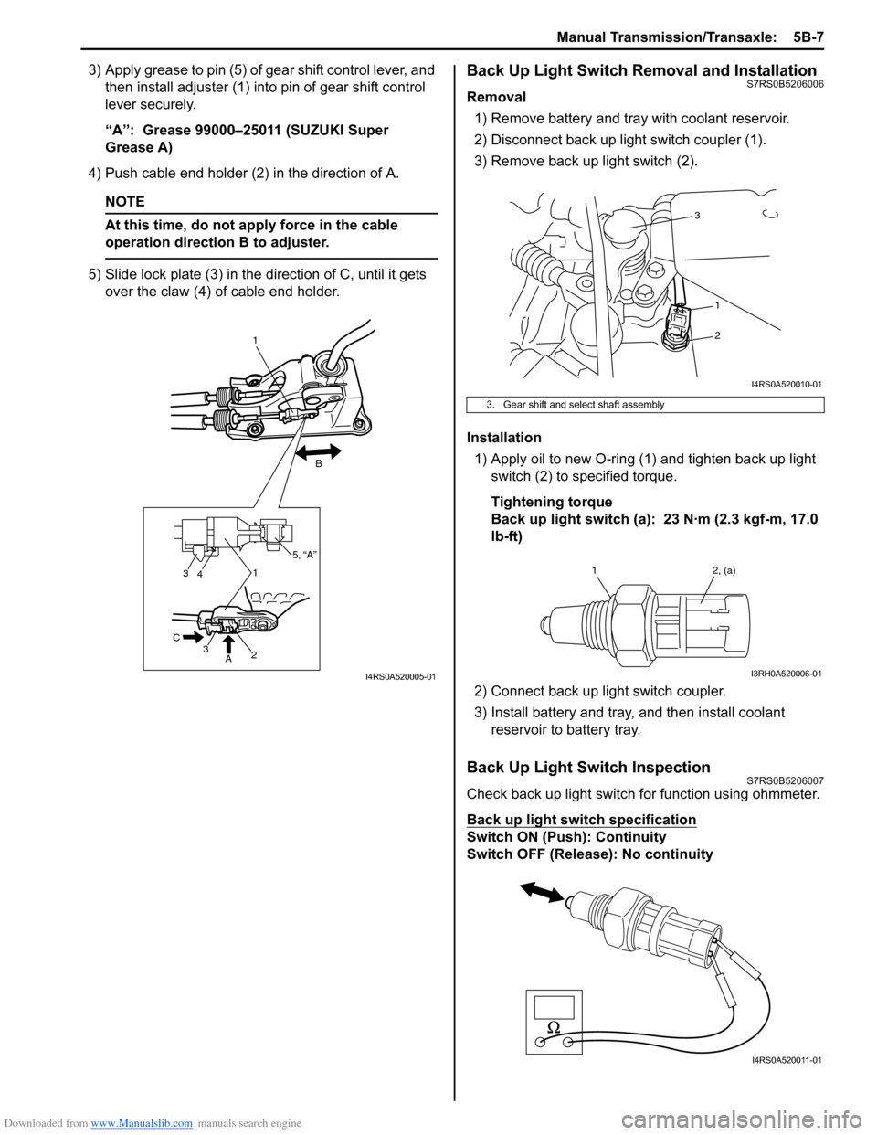
3) Apply grease to pin (5) of gear shift control lever, and then install adjuster (1) into pin of gear shift control
lever securely.
“A”: Grease 99000–25011 (SUZUKI Super
Grease A)
4) Push cable end holder (2) in the direction of A.
NOTE
At this time, do not a pply force in the cable
operation direction B to adjuster.
5) Slide lock plate (3) in the direction of C, until it gets over the claw (4) of cable end holder.
Back Up Light Switch Removal and InstallationS7RS0B5206006
Removal
1) Remove battery and tray with coolant reservoir.
2) Disconnect back up light switch coupler (1).
3) Remove back up light switch (2).
Installation 1) Apply oil to new O-ring (1) and tighten back up light switch (2) to specified torque.
Tightening torque
Back up light switch (a): 23 N·m (2.3 kgf-m, 17.0
lb-ft)
2) Connect back up light switch coupler.
3) Install battery and tray, and then install coolant reservoir to battery tray.
Back Up Light Switch InspectionS7RS0B5206007
Check back up light switch for function using ohmmeter.
Back up light switch specification
Switch ON (Push): Continuity
Switch OFF (Release ): No continuity
3
3
41
2
A
C
1
B
5, “A”
I4RS0A520005-01
3. Gear shift and select shaft assembly
3
1
2
I4RS0A520010-01
1 2, (a)
I3RH0A520006-01
I4RS0A520011-01
Page 825 of 1496
Downloaded from www.Manualslib.com manuals search engine Manual Transmission/Transaxle: 5B-11
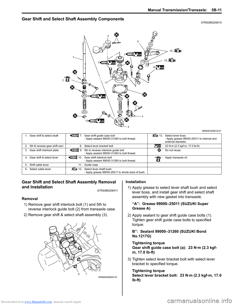
Gear Shift and Select Shaft Assembly ComponentsS7RS0B5206010
Gear Shift and Select Shaft Assembly Removal
and Installation
S7RS0B5206011
Removal1) Remove gear shift interlock bolt (1) and 5th to reverse interlock guide bolt (2) from transaxle case.
2) Remove gear shift & select shaft assembly (3). Installation
1) Apply grease to select lever shaft bush and select lever boss, and install gear shift and select shaft
assembly with new gasket into transaxle.
“A”: Grease 99000–25011 (SUZUKI Super
Grease A)
2) Apply sealant to gear shift guide case bolts (1). Tighten gear shift guide case bolts to specified
torque.
B”: Sealant 99000–31260 (SUZUKI Bond
No.1217G)
Tightening torque
Gear shift guide case bolt (a): 23 N·m (2.3 kgf-
m, 17.0 lb-ft)
3) Tighten select lever brac ket bolt with select lever
bracket to specified torque.
Tightening torque
Select lever bracket bolt: 23 N·m (2.3 kgf-m, 17.0
lb-ft)
I6RS0C520010-01
1. Gear shift & select shaft 7. Gear shift guide case bolt
: Apply sealant 99000-31260 to bolt thread. 13. Select lever boss
: Apply grease 99000-25011 to internal and
external diameter.
2. 5th & reverse gear shift cam 8. Select lever bracket bolt : 23 N⋅m (2.3 kgf-m, 17.0 lb-ft)
3. Gear shift interlock plate 9. 5th to reverse interlock guide bolt
: Apply sealant 99000-31260 to bolt thread. : Do not reuse.
4. Gear shift & select lever 10. Gear shift interlock bolt
: Apply sealant 99000-31260 to bolt thread. : Apply transaxle oil.
5. Shift cable lever 11. Guide case
6. Select cable lever 12. Select lever shaft bush
: Apply grease 99000-25011 to whole area of bush.
3
12I4RS0A520024-01