Page 454 of 1496
Downloaded from www.Manualslib.com manuals search engine 2B-21 Front Suspension:
Special Tools and Equipment
Special ToolS7RS0B2208001
09900–0041109900–00413
Hexagon bit socket Hexagon bit (5 mm)
�) / �) / �) / �) / �)�) / �) / �)
09900–00414 09913–65810
Hexagon bit (6 mm) Crankshaft bearing puller
�) / �)�)
09913–75510 09913–75520
Bearing installer Bearing installer
�) / �)�)
09913–75821 09913–85230
Bearing installer attachment Bearing remover tool
�) / �)�)
09926–68310 09940–71431
Differential bevel pinion
bearing installer Suspension spring
compressor
�)�) / �)
09942–15511 09943–17912
Sliding hammer Wheel hub remover
�)�)
09943–76310 09951–18210
Bush remover Oil seal remover & installer
No. 2
�) / �)�)
Page 648 of 1496
Downloaded from www.Manualslib.com manuals search engine 5A-4 Automatic Transmission/Transaxle:
1
2
3
4567891011121314151617
18 19 20 21 22 23
24 25
26
27
28I3RM0B510001-01
1. Drive plate 11. 1st and reverse brake 21. Rear sun gear
2. Torque converter clutch (TCC) 12. Ring gear22. Front sun gear
3. Torque converter 13. Long planet pinion23. Short planet pinion
4. Input shaft 14. One-way No.2 clutch 24. Countershaft
5. Oil pump 15. 2nd brake25. Reduction driven gear
6. Direct clutch drum (double as sensor ro tor for input shaft speed sensor) 16. One-way No.1 clutch 26. Differential case assembly
7. Direct clutch 17. O/D and 2nd coast brake 27. Final gear
8. Parking lock gear 18. Intermediate shaft28.Output shaft speed sensor drive gear
9. Reduction drive gear 19. Forward clutch
10. Planet carrier 20. Reverse clutch
Page 649 of 1496

Downloaded from www.Manualslib.com manuals search engine Automatic Transmission/Transaxle: 5A-5
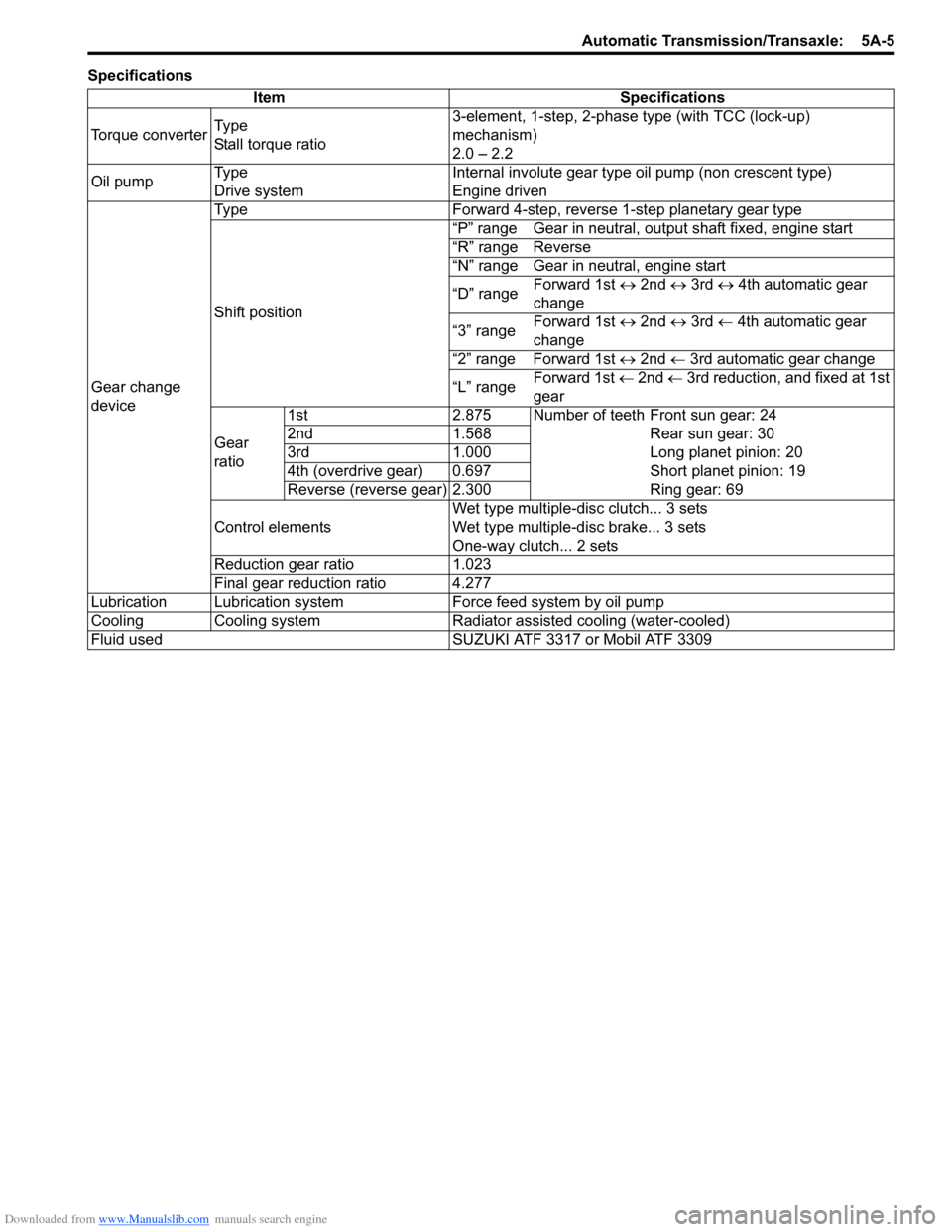
SpecificationsItem Specifications
Torque converter Ty p e
Stall torque ratio 3-element, 1-step, 2-phase type (with TCC (lock-up)
mechanism)
2.0 – 2.2
Oil pump Ty p e
Drive system Internal involute gear type oil pump (non crescent type)
Engine driven
Gear change
device Type Forward 4-step, reverse 1-step planetary gear type
Shift position
“P” range Gear in neutral, output shaft fixed, engine start
“R” range Reverse
“N” range Gear in neutral, engine start
“D” range
Forward 1st
↔ 2nd ↔ 3rd ↔ 4th automatic gear
change
“3” range Forward 1st
↔ 2nd ↔ 3rd ← 4th automatic gear
change
“2” range Forward 1st ↔ 2nd ← 3rd automatic gear change
“L” range Forward 1st
← 2nd ← 3rd reduction, and fixed at 1st
gear
Gear
ratio 1st 2.875 Number of teeth Front sun gear: 24
2nd 1.568 Rear sun gear: 30
3rd 1.000 Long planet pinion: 20
4th (overdrive gear) 0.697 Short planet pinion: 19
Reverse (reverse gear) 2.300 Ring gear: 69
Control elements Wet type multiple-disc clutch... 3 sets
Wet type multiple-d
isc brake... 3 sets
One-way clutch... 2 sets
Reduction gear ratio 1.023
Final gear reduction ratio 4.277
Lubrication Lubrication system Force feed system by oil pump
Cooling Cooling system Radiator assisted cooling (water-cooled)
Fluid used SUZUKI ATF 3317 or Mobil ATF 3309
Page 650 of 1496

Downloaded from www.Manualslib.com manuals search engine 5A-6 Automatic Transmission/Transaxle:
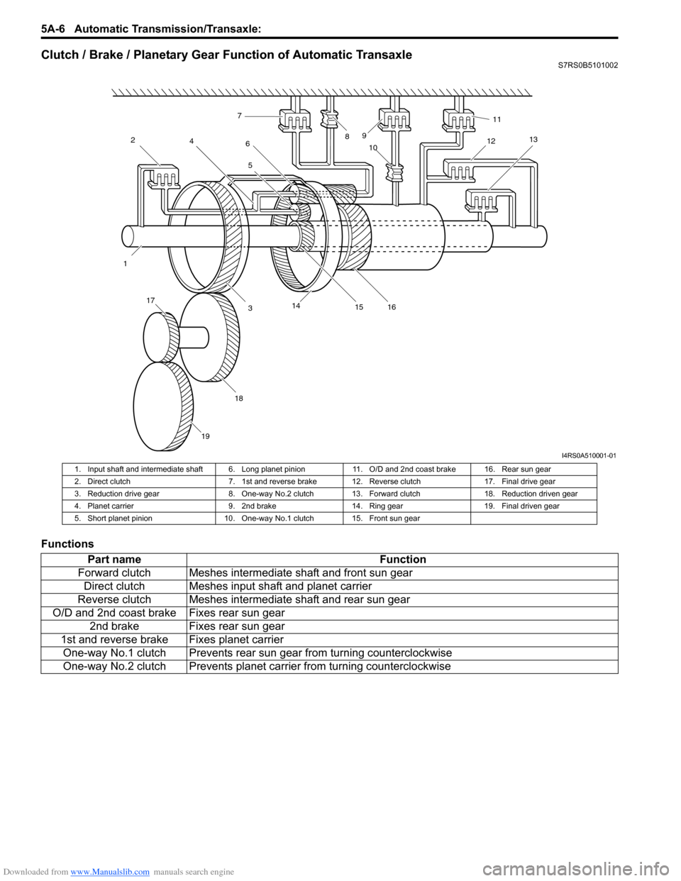
Clutch / Brake / Planetary Gear Function of Automatic TransaxleS7RS0B5101002
Functions
12
4
3 5
6
7
89
10 11
12 13
14 15 16
17
18
19
I4RS0A510001-01
1. Input shaft and intermediate shaft 6. Long planet pi nion 11. O/D and 2nd coast brake 16. Rear sun gear
2. Direct clutch 7. 1st and reverse brak e 12. Reverse clutch 17. Final drive gear
3. Reduction drive gear 8. One-way No.2 clutch 13. Forward clutch 18. Reduction driven gear
4. Planet carrier 9. 2nd brake 14. Ring gear 19. Final driven gear
5. Short planet pinion 10. One-way No.1 clutch 15. Front sun gear
Part name Function
Forward clutch Meshes intermediate shaft and front sun gear Direct clutch Meshes input shaft and planet carrier
Reverse clutch Meshes intermediate shaft and rear sun gear
O/D and 2nd coast brake Fixes rear sun gear 2nd brake Fixes rear sun gear
1st and reverse brake Fixes planet carrier One-way No.1 clutch Prevents rear sun gear from turning counterclockwise
One-way No.2 clutch Prevents planet ca rrier from turning counterclockwise
Page 847 of 1496

Downloaded from www.Manualslib.com manuals search engine Manual Transmission/Transaxle: 5B-33
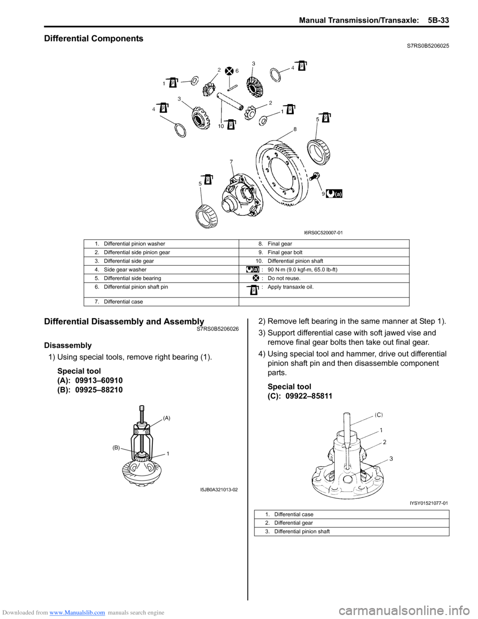
Differential ComponentsS7RS0B5206025
Differential Disassembly and AssemblyS7RS0B5206026
Disassembly1) Using special tools, remove right bearing (1).
Special tool
(A): 09913–60910
(B): 09925–88210 2) Remove left bearing in the same manner at Step 1).
3) Support differential case with soft jawed vise and
remove final gear bolts then take out final gear.
4) Using special tool and hammer, drive out differential pinion shaft pin and then disassemble component
parts.
Special tool
(C): 09922–85811
1. Differential pinion washer 8. Final gear
2. Differential side pinion gear 9. Final gear bolt
3. Differential side gear 10. Differential pinion shaft
4. Side gear washer : 90 N⋅m (9.0 kgf-m, 65.0 lb-ft)
5. Differential side bearing : Do not reuse.
6. Differential pinion shaft pin : Apply transaxle oil.
7. Differential case
I6RS0C520007-01
1(B)
(A)
I5JB0A321013-02
1. Differential case
2. Differential gear
3. Differential pinion shaft
IYSY01521077-01
Page 848 of 1496

Downloaded from www.Manualslib.com manuals search engine 5B-34 Manual Transmission/Transaxle:
Assembly
Judging from abnormality noted before disassembly and
what is found through visual check of component parts
after disassembly, prepare replacing parts and proceed
to reassembly. Make sure that all parts are clean.
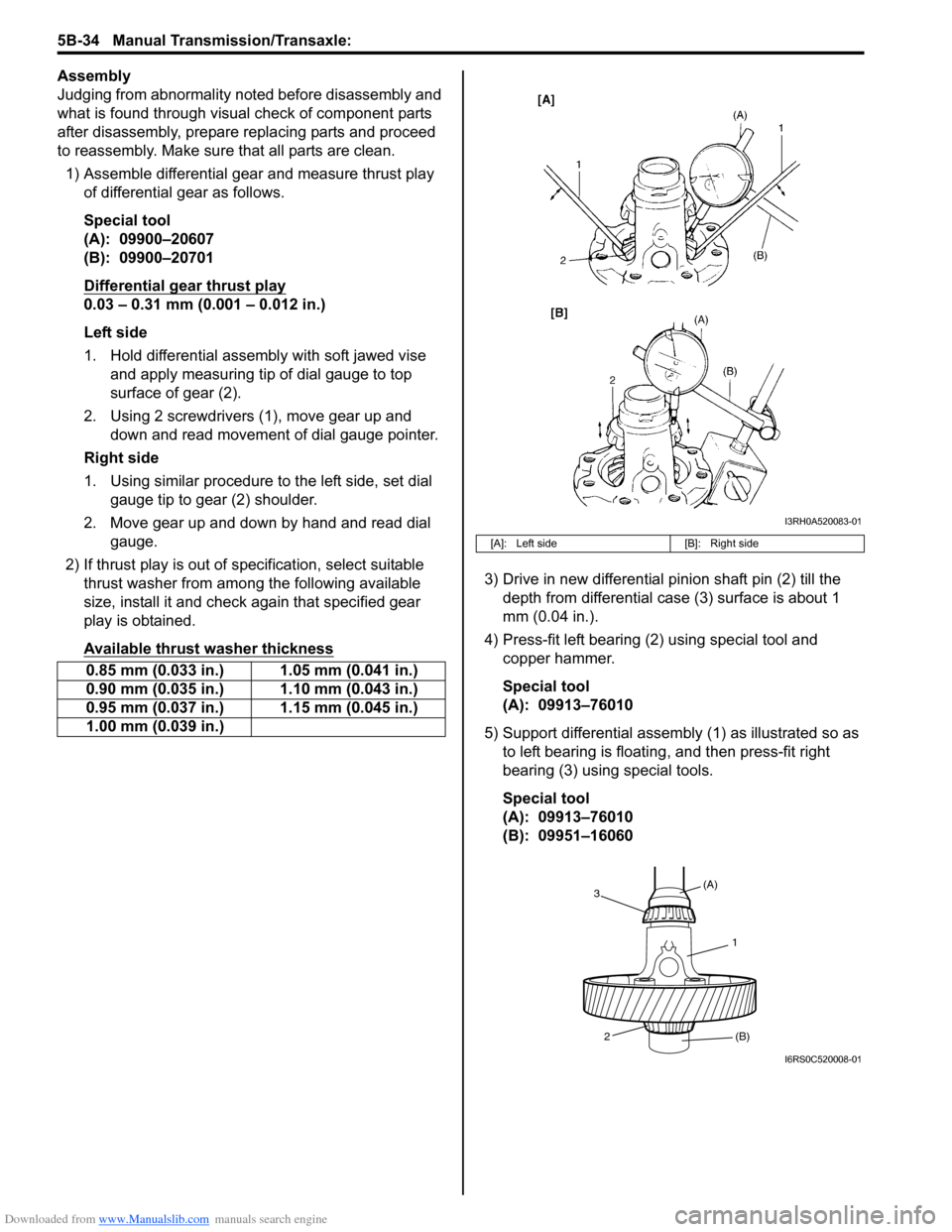
1) Assemble differential gear and measure thrust play
of differential gear as follows.
Special tool
(A): 09900–20607
(B): 09900–20701
Differential gear thrust play
0.03 – 0.31 mm (0.001 – 0.012 in.)
Left side
1. Hold differential assembly with soft jawed vise and apply measuring tip of dial gauge to top
surface of gear (2).
2. Using 2 screwdrivers (1), move gear up and down and read movement of dial gauge pointer.
Right side
1. Using similar procedure to the left side, set dial gauge tip to gear (2) shoulder.
2. Move gear up and down by hand and read dial gauge.
2) If thrust play is out of sp ecification, select suitable
thrust washer from among the following available
size, install it and check again that specified gear
play is obtained.
Available thrust washer thickness
3) Drive in new differential pinion shaft pin (2) till the depth from differential case (3) surface is about 1
mm (0.04 in.).
4) Press-fit left bearing (2) using special tool and copper hammer.
Special tool
(A): 09913–76010
5) Support differential assembly (1) as illustrated so as to left bearing is floating , and then press-fit right
bearing (3) using special tools.
Special tool
(A): 09913–76010
(B): 09951–16060
0.85 mm (0.033 in.) 1.05 mm (0.041 in.)
0.90 mm (0.035 in.) 1.10 mm (0.043 in.)
0.95 mm (0.037 in.) 1.15 mm (0.045 in.)
1.00 mm (0.039 in.)
[A]: Left side
[B]: Right side
I3RH0A520083-01
1
(A)
3
2 (B)
I6RS0C520008-01
Page 866 of 1496
Downloaded from www.Manualslib.com manuals search engine 5C-14 Clutch:
Special Tools and Equipment
Recommended Service MaterialS7RS0B5308001
NOTE
Required service material is also described in the following.
“Clutch Fluid Pipe and Hose Components”
“Clutch Pedal and Clutch Pedal Bracket Components”
“Clutch Cover, Clutch Disc and Flywheel Components”
Special ToolS7RS0B5308002
Material SUZUKI recommended product or Specification Note
Grease SUZUKI Super Grease A P/No.: 99000–25011�) / �) / �) / �)
SUZUKI Silicone Grease P/No.: 99000–25100�) / �)
SUZUKI Super Grease I P/No.: 99000–25210�) / �)
09921–26020 09922–46010
Bearing remover Clutch bush remover
�)�) / �)
09923–36320 09923–46020
Clutch center guide (15 mm) Joint pipe
�)�)
09923–46030 09924–17811
Joint pipe Flywheel holder
�)�) / �) / �) / �)
09925–98210 09925–98221
Input shaft bearing inst aller Bearing installer
�)�)
09930–30104 09943–88211
Sliding shaft Pinion bearing installer
�) / �)�)
Page 871 of 1496

Downloaded from www.Manualslib.com manuals search engine Steering General Diagnosis: 6A-2
Diagnostic Information and Procedures
Steering Symptom DiagnosisS7RS0B6104001
ConditionPossible cause Correction / Reference Item
Hard steering Tire not adequately inflated Inflate tires to proper pressure.
Malfunction of power steering system Check and correct.
Bind in tie-rod end ball studs or lower
ball joints Replace tie-rod end or front suspension arm.
Disturbed front wheel alignment Check and adjust front wheel alignment.
Bind in steering column Repair or replace steering column.
Rack and pinion adjustment Check and adjustment rack and pinion torque.
Too much play in steering Wheel bearings worn Replace wheel bearing.
Loose steering gear case bolts Tighten gear case bolts.
Faulty steering gear case assembly Replace steering gear case assembly.
Worn steering shaft joints Replace joint.
Worn tie-rod ends or tie-rod inside ball
joints Replace tie-rod end or tie-rod.
Worn lower ball joints Replace front suspension control arm.
Rack and pinion adjustment Check and adjustment rack and pinion torque.
Poor return ability Bind in tie-rod end ball studs Replace tie-rod end.
Bind in ball joints Replace front suspension control arm.
Bind in steering column Repair or replace steering column.
Disturbed front end alignment Check and adjust front end alignment.
Faulty steering gear case assembly Replace steering gear case assembly.
Tires not adequately inflated Adjust tire pressure.
Rack and pinion adjustment Check and adjustment rack and pinion torque.
Rack and pinion noise
(Rattle or chuckle) Loose steering gear case bolts
Tighten steering gear case bolts.
Rack and pinion adjustment Check and adjustment rack and pinion torque.
Faulty steering gear case assembly Replace steering gear case assembly.
Broken or other wise damaged wheel
bearing(s) Replace wheel bearing(s).
Wander or poor steering
stability Mismatched or uneven tires
Replace or inflate tires to proper pressure.
Loosen ball joints and tie-rod ends Replace suspension control arm or tie-rod end.
Faulty struts or mountings Replace strut or repair mounting.
Loose stabilizer bar Tighten or replace stabilizer bar or bush.
Broken or sagging springs Replace spring.
Rack and pinion adjustment Check and adjustment rack and pinion torque.
Disturbed front wheel alignment Check and adjust front wheel alignment.
Faulty steering gear case assembly Replace steering gear case assembly.
Erratic steering when
braking Worn wheel bearing(s)
Replace wheel bearing(s).
Broken or sagging spring(s) Replace coil spring(s).
Wheel tires are inflated unequally Inflate tires to proper pressure.
Disturbed front wheel alignment Check and adjust front wheel alignment.
Brakes not working in unison Check and repair brake system.
Leaking caliper Repair or replace caliper.
Warped discs Replace brake disc.
Badly worn brake pads Replace brake pads.