2005 SUZUKI SWIFT blower
[x] Cancel search: blowerPage 190 of 1496
Downloaded from www.Manualslib.com manuals search engine 1A-140 Engine General Information and Diagnosis:
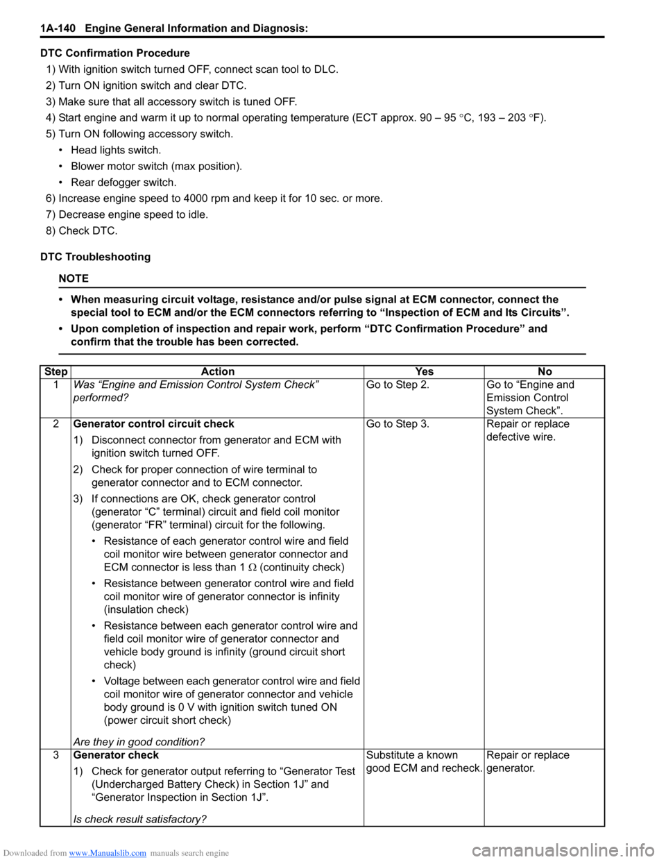
DTC Confirmation Procedure1) With ignition switch turned OFF, connect scan tool to DLC.
2) Turn ON ignition switch and clear DTC.
3) Make sure that all accessory switch is tuned OFF.
4) Start engine and warm it up to normal operating temperature (ECT approx. 90 – 95 °C, 193 – 203 °F).
5) Turn ON following accessory switch. • Head lights switch.
• Blower motor switch (max position).
• Rear defogger switch.
6) Increase engine speed to 4000 rpm and keep it for 10 sec. or more.
7) Decrease engine speed to idle.
8) Check DTC.
DTC Troubleshooting
NOTE
• When measuring circuit voltage, resistance and/ or pulse signal at ECM connector, connect the
special tool to ECM and/or the ECM connectors re ferring to “Inspection of ECM and Its Circuits”.
• Upon completion of inspection and repair work, perform “DTC Confirmation Procedure” and confirm that the trouble has been corrected.
Step Action YesNo
1 Was “Engine and Emission Control System Check”
performed? Go to Step 2.
Go to “Engine and
Emission Control
System Check”.
2 Generator control circuit check
1) Disconnect connector from generator and ECM with
ignition switch turned OFF.
2) Check for proper connection of wire terminal to generator connector and to ECM connector.
3) If connections are OK, check generator control (generator “C” terminal) circuit and field coil monitor
(generator “FR” terminal) circuit for the following.
• Resistance of each generato r control wire and field
coil monitor wire between generator connector and
ECM connector is less than 1 Ω (continuity check)
• Resistance between generator control wire and field coil monitor wire of generator connector is infinity
(insulation check)
• Resistance between each generator control wire and field coil monitor wire of generator connector and
vehicle body ground is infinity (ground circuit short
check)
• Voltage between each generator control wire and field
coil monitor wire of generator connector and vehicle
body ground is 0 V with ignition switch tuned ON
(power circuit short check)
Are they in good condition? Go to Step 3.
Repair or replace
defective wire.
3 Generator check
1) Check for generator output referring to “Generator Test
(Undercharged Battery Check) in Section 1J” and
“Generator Inspection in Section 1J”.
Is check result satisfactory? Substitute a known
good ECM and recheck.
Repair or replace
generator.
Page 191 of 1496
Downloaded from www.Manualslib.com manuals search engine Engine General Information and Diagnosis: 1A-141
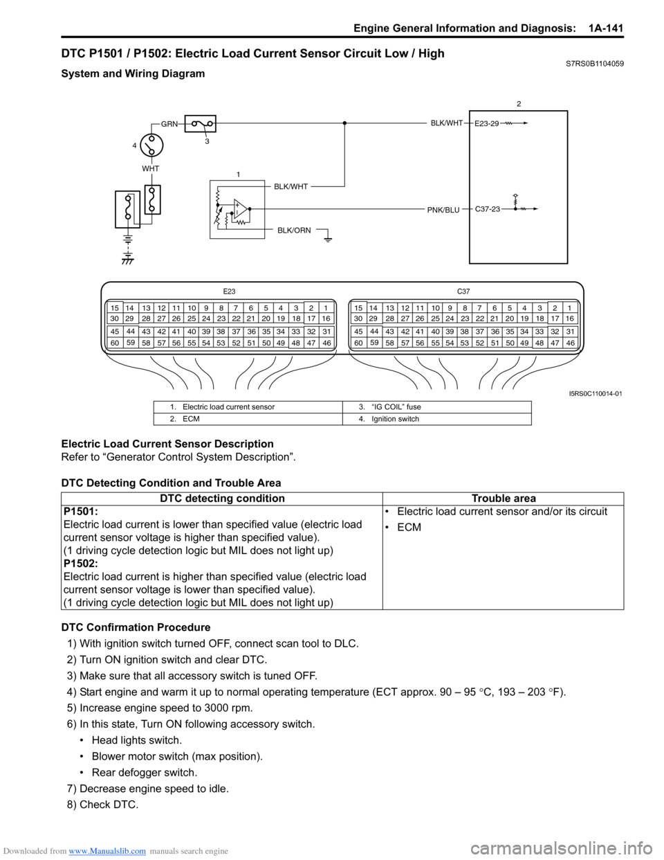
DTC P1501 / P1502: Electric Load Current Sensor Circuit Low / HighS7RS0B1104059
System and Wiring Diagram
Electric Load Current Sensor Description
Refer to “Generator Control System Description”.
DTC Detecting Condition and Trouble Area
DTC Confirmation Procedure1) With ignition switch turned OFF, connect scan tool to DLC.
2) Turn ON ignition switch and clear DTC.
3) Make sure that all accessory switch is tuned OFF.
4) Start engine and warm it up to normal operating temperature (ECT approx. 90 – 95 °C, 193 – 203 °F).
5) Increase engine speed to 3000 rpm.
6) In this state, Turn ON following accessory switch.
• Head lights switch.
• Blower motor switch (max position).
• Rear defogger switch.
7) Decrease engine speed to idle.
8) Check DTC.
E23 C37
34
1819
567
1011
17
20
47 46
495051
2122
52 16
25 9
24
14
29
55
57 54 53
59
60 58 2
262728
15
30
56 4832 31
34353637
40
42 39 38
44
45 43 41 331
1213
238
34
1819
567
1011
17
20
47 46
495051
2122
52 16
25 9
24
14
29
55
57 54 53
59
60 58 2
262728
15
30
56 4832 31
34353637
40
42 39 38
44
45 43 41 331
1213
238
BLK/WHT
WHT
GRN
4
3 2
E23-29
1
C37-23PNK/BLU
BLK/ORN
BLK/WHT
I5RS0C110014-01
1. Electric load current sensor
3. “IG COIL” fuse
2. ECM 4. Ignition switch
DTC detecting condition Trouble area
P1501:
Electric load current is lower th an specified value (electric load
current sensor voltage is higher than specified value).
(1 driving cycle detection logic but MIL does not light up)
P1502:
Electric load current is higher than specified value (electric load
current sensor voltage is lo wer than specified value).
(1 driving cycle detection logic but MIL does not light up) • Electric load current sensor and/or its circuit
•ECM
Page 228 of 1496
Downloaded from www.Manualslib.com manuals search engine 1A-178 Engine General Information and Diagnosis:
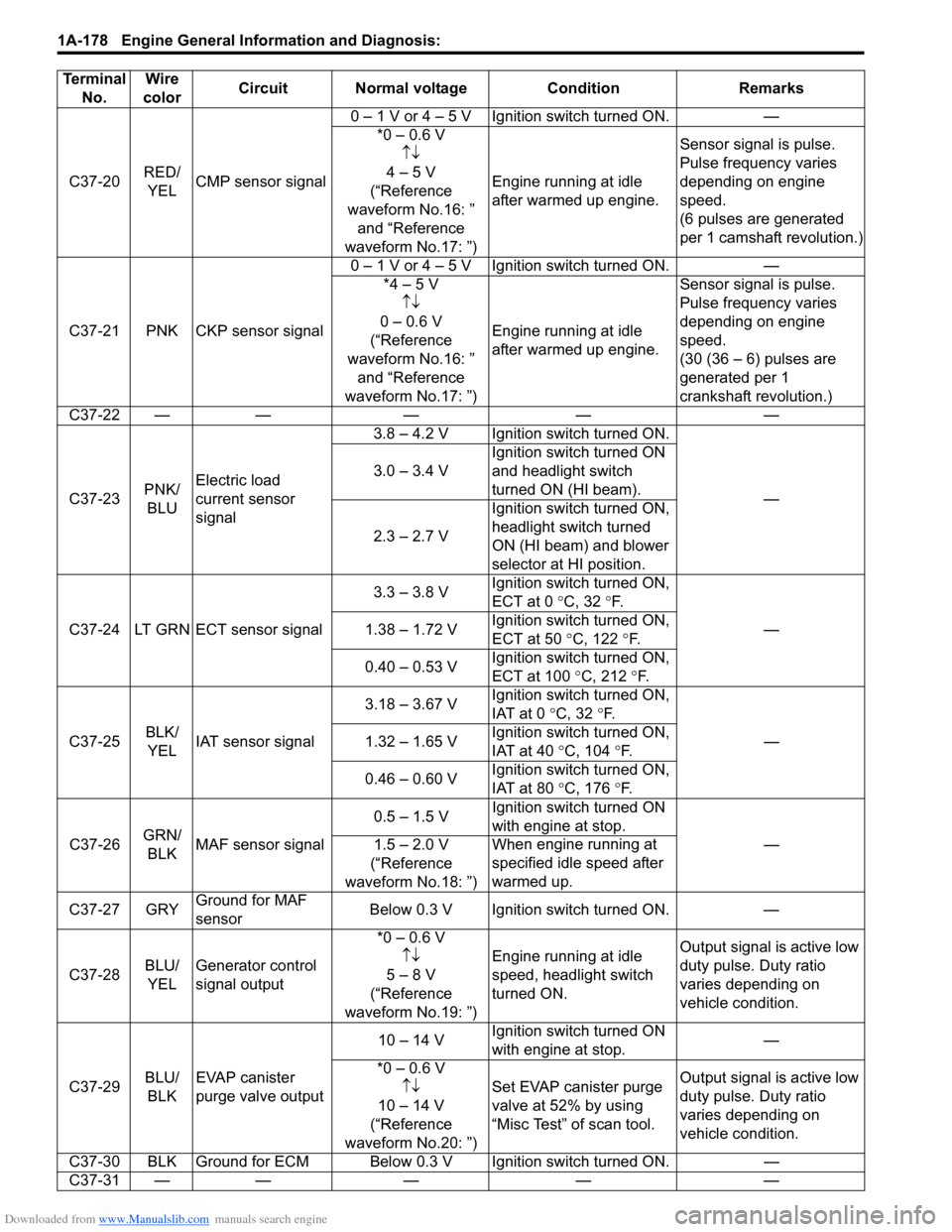
C37-20RED/
YEL CMP sensor signal 0 – 1 V or 4 – 5 V Ignition switch turned ON. —
*0 – 0.6 V↑↓
4 – 5 V
(“Reference
waveform No.16: ” and “Reference
waveform No.17: ”) Engine running at idle
after warmed up engine.
Sensor signal is pulse.
Pulse frequency varies
depending on engine
speed.
(6 pulses are generated
per 1 camshaft revolution.)
C37-21 PNK CKP sensor signal 0 – 1 V or 4 – 5 V Ignition switch turned ON. —
*4 – 5 V↑↓
0 – 0.6 V
(“Reference
waveform No.16: ” and “Reference
waveform No.17: ”) Engine running at idle
after warmed up engine. Sensor signal is pulse.
Pulse frequency varies
depending on engine
speed.
(30 (36 – 6) pulses are
generated per 1
crankshaft revolution.)
C37-22 — — — — —
C37-23 PNK/
BLU Electric load
current sensor
signal 3.8 – 4.2 V Ignition switch turned ON.
—
3.0 – 3.4 V
Ignition switch turned ON
and headlight switch
turned ON (HI beam).
2.3 – 2.7 V Ignition switch turned ON,
headlight switch turned
ON (HI beam) and blower
selector at HI position.
C37-24 LT GRN ECT sensor signal 3.3 – 3.8 V
Ignition switch turned ON,
ECT at 0
°C, 32 °F.
—
1.38 – 1.72 V Ignition switch turned ON,
ECT at 50
°C, 122 °F.
0.40 – 0.53 V Ignition switch turned ON,
ECT at 100
°C, 212 °F.
C37-25 BLK/
YEL IAT sensor signal 3.18 – 3.67 V
Ignition switch turned ON,
IAT at 0
°C, 32 °F.
—
1.32 – 1.65 V Ignition switch turned ON,
IAT at 40
°C, 104 °F.
0.46 – 0.60 V Ignition switch turned ON,
IAT at 80
°C, 176 °F.
C37-26 GRN/
BLK MAF sensor signal 0.5 – 1.5 V
Ignition switch turned ON
with engine at stop.
—
1.5 – 2.0 V
(“Reference
waveform No.18: ”) Wh
en engine running at
specified idle speed after
warmed up.
C37-27 GRY Ground for MAF
sensor Below 0.3 V Ignition switch turned ON.
—
C37-28 BLU/
YEL Generator control
signal output *0 – 0.6 V
↑↓
5 – 8 V
(“Reference
waveform No.19: ”) Engine running at idle
speed, headlight switch
turned ON.
Output signal is active low
duty pulse. Duty ratio
varies depending on
vehicle condition.
C37-29 BLU/
BLK EVAP canister
purge valve output 10 – 14 V
Ignition switch turned ON
with engine at stop. —
*0 – 0.6 V ↑↓
10 – 14 V
(“Reference
waveform No.20: ”) Set EVAP canister purge
valve at 52% by using
“Misc Test” of scan tool.
Output signal is active low
duty pulse. Duty ratio
varies depending on
vehicle condition.
C37-30 BLK Ground for ECM Below 0.3 V Ignition switch turned ON. —
C37-31 — —— — —
Terminal
No. Wire
color Circuit Normal voltage
ConditionRemarks
Page 231 of 1496
Downloaded from www.Manualslib.com manuals search engine Engine General Information and Diagnosis: 1A-181
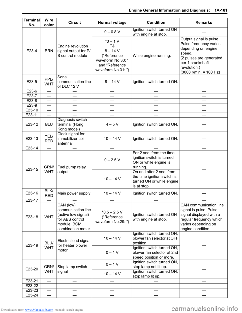
E23-4 BRNEngine revolution
signal output for P/
S control module 0 – 0.8 V
Ignition switch turned ON
with engine at stop. —
*0 – 1 V ↑↓
8 – 14 V
(“Reference
waveform No.30: ” and “Reference
waveform No.31: ”) While engine running. Output signal is pulse.
Pulse frequency varies
depending on engine
speed.
(2 pulses are generated
per 1 crankshaft
revolution.)
(3000 r/min. = 100 Hz)
E23-5 PPL/
WHT Serial
communication line
of DLC 12 V
8 – 14 V Ignition switch turned ON. —
E23-6 — — — — —
E23-7 — — — — —
E23-8 — — — — —
E23-9 — — — — —
E23-10 — — — — — E23-11 — — — — —
E23-12 BLU Diagnosis switch
terminal (Hong
Kong model) 4 – 5 V Ignition switch turned ON. —
E23-13 YEL/
RED Clock signal for
immobilizer coil
antenna
10 – 14 V Ignition switch turned ON. —
E23-14 — — — — —
E23-15 GRN/
WHT Fuel pump relay
output 0 – 2.5 V
For 2 sec. from the time
ignition switch is turned
ON or while engine is
running.
—
10 – 14 V On and after 2 sec. from
the time ignition switch is
turned ON or while engine
is at stop.
E23-16 BLK/
RED Main power supply 10 – 14 V Ignition switch turned ON. —
E23-17 — — — — —
E23-18 WHT CAN (low)
communication line
(active low signal)
for ABS control
module, BCM,
combination meter *0.5 – 2.5 V
(“Reference
waveform No.29: ”) Ignition switch turned ON
with engine at stop. CAN communication line
signal is pulse. Pulse
signal displayed with a
regular frequency which
varies depending on
engine condition.
E23-19 BLU/
WHT Electric load signal
for heater blower
motor 10 – 14 V
Ignition switch turned ON,
blower fan selector at OFF
position.
—
0 – 1 V Ignition switch turned ON,
blower fan selector at 2nd
speed position or more.
E23-20 GRN/
WHT Stop lamp switch
signal 0 – 1 V
Ignition switch turned ON,
stop lamp not lit up.
—
10 – 14 V Ignition switch turned ON,
stop lamp lit up.
E23-21 — — — — —
E23-22 — — — — —
E23-23 — — — — —
E23-24 — — — — —
Terminal
No. Wire
color Circuit Normal voltage Condition Remarks
Page 233 of 1496
Downloaded from www.Manualslib.com manuals search engine Engine General Information and Diagnosis: 1A-183
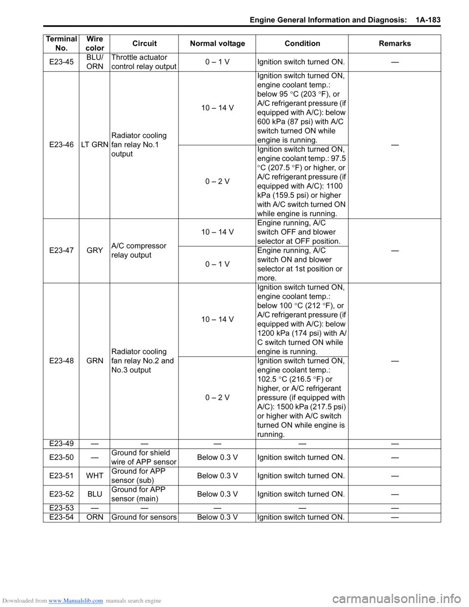
E23-45BLU/
ORNThrottle actuator
control relay output
0 – 1 V Ignition switch turned ON. —
E23-46 LT GRN Radiator cooling
fan relay No.1
output 10 – 14 V
Ignition switch turned ON,
engine coolant temp.:
below 95
°C (203 ° F), or
A/C refrigerant pressure (if
equipped with A/C): below
600 kPa (87 psi) with A/C
switch turned ON while
engine is running. —
0 – 2 V Ignition switch turned ON,
engine coolant temp.: 97.5
°
C (207.5 ° F) or higher, or
A/C refrigerant pressure (if
equipped with A/C): 1100
kPa (159.5 psi) or higher
with A/C switch turned ON
while engine is running.
E23-47 GRY A/C compressor
relay output 10 – 14 V
Engine running, A/C
switch OFF and blower
selector at OFF position.
—
0 – 1 V Engine running, A/C
switch ON and blower
selector at 1st position or
more.
E23-48 GRN Radiator cooling
fan relay No.2 and
No.3 output 10 – 14 V
Ignition switch turned ON,
engine coolant temp.:
below 100
°C (212 °F), or
A/C refrigerant pressure (if
equipped with A/C): below
1200 kPa (174 psi) with A/
C switch turned ON while
engine is running. —
0 – 2 V Ignition switch turned ON,
engine coolant temp.:
102.5
°C (216.5 °F) or
higher, or A/C refrigerant
pressure (if equipped with
A/C): 1500 kPa (217.5 psi)
or higher with A/C switch
turned ON while engine is
running.
E23-49 — — — — —
E23-50 — Ground for shield
wire of APP sensor Below 0.3 V Ignition switch turned ON. —
E23-51 WHT Ground for APP
sensor (sub) Below 0.3 V Ignition switch turned ON. —
E23-52 BLU Ground for APP
sensor (main) Below 0.3 V Ignition switch turned ON. —
E23-53 — — — — —
E23-54 ORN Ground for sensors Below 0.3 V Ignition switch turned ON. —
Terminal
No. Wire
color Circuit Normal voltage Condition Remarks
Page 234 of 1496
Downloaded from www.Manualslib.com manuals search engine 1A-184 Engine General Information and Diagnosis:
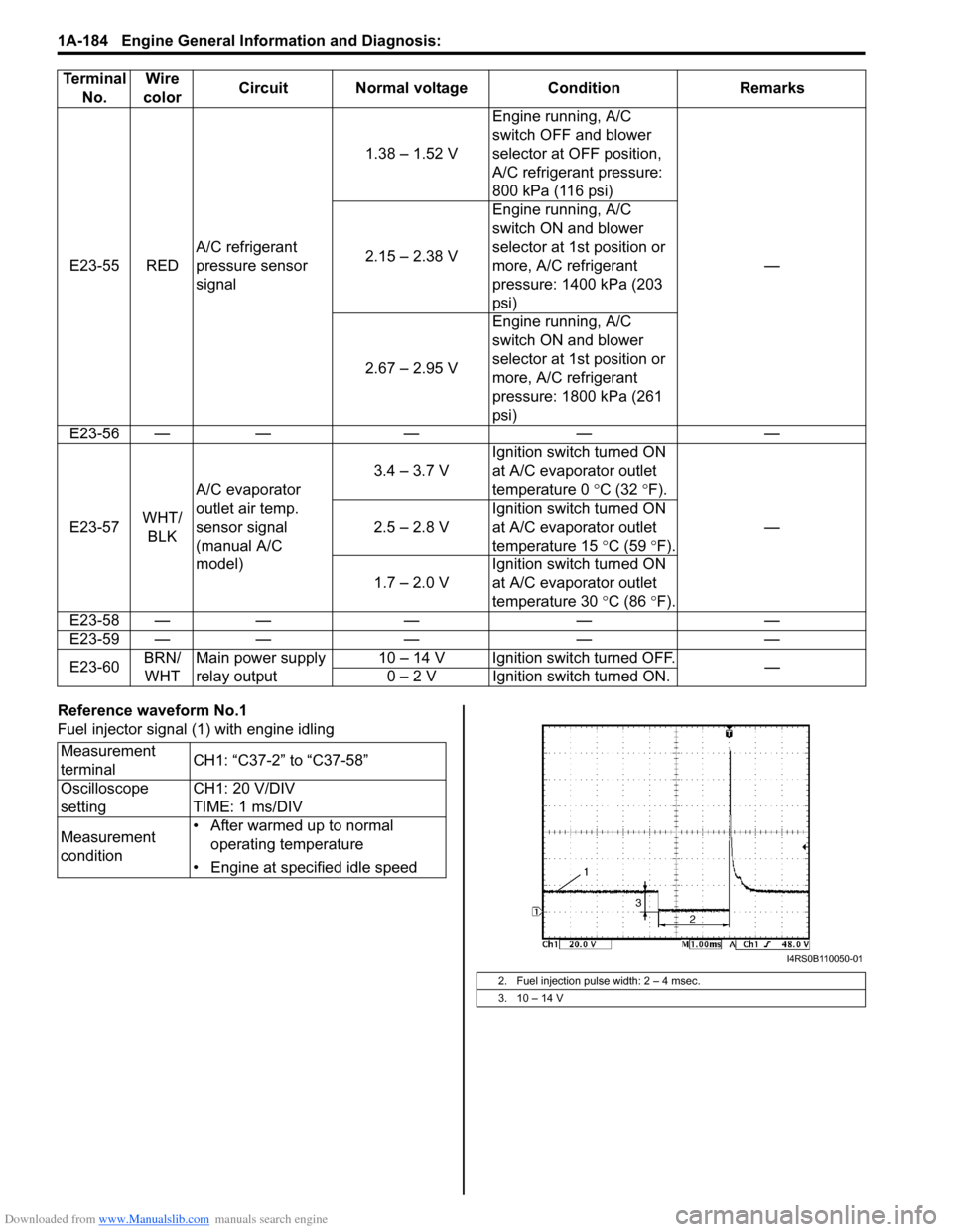
Reference waveform No.1
Fuel injector signal (1) with engine idling
E23-55 RED
A/C refrigerant
pressure sensor
signal 1.38 – 1.52 V
Engine running, A/C
switch OFF and blower
selector at OFF position,
A/C refrigerant pressure:
800 kPa (116 psi)
—
2.15 – 2.38 V Engine running, A/C
switch ON and blower
selector at 1st position or
more, A/C refrigerant
pressure: 1400 kPa (203
psi)
2.67 – 2.95 V Engine running, A/C
switch ON and blower
selector at 1st position or
more, A/C refrigerant
pressure: 1800 kPa (261
psi)
E23-56 — — — — —
E23-57 WHT/
BLK A/C evaporator
outlet air temp.
sensor signal
(manual A/C
model) 3.4 – 3.7 V
Ignition switch turned ON
at A/C evaporator outlet
temperature 0
°C (32 °F).
—
2.5 – 2.8 V Ignition switch turned ON
at A/C evaporator outlet
temperature 15
°C (59 °F).
1.7 – 2.0 V Ignition switch turned ON
at A/C evaporator outlet
temperature 30
°C (86 °F).
E23-58 — — — — —
E23-59 — — — — —
E23-60 BRN/
WHT Main power supply
relay output 10 – 14 V Ignition switch turned OFF.
—
0 – 2 V Ignition switch turned ON.
Terminal
No. Wire
color Circuit Normal voltage Condition Remarks
Measurement
terminal CH1: “C37-2” to “C37-58”
Oscilloscope
setting CH1: 20 V/DIV
TIME: 1 ms/DIV
Measurement
condition • After warmed up to normal
operating temperature
• Engine at specified idle speed
2. Fuel injection pulse width: 2 – 4 msec.
3. 10 – 14 V
I4RS0B110050-01
Page 255 of 1496
Downloaded from www.Manualslib.com manuals search engine Engine General Information and Diagnosis: 1A-205
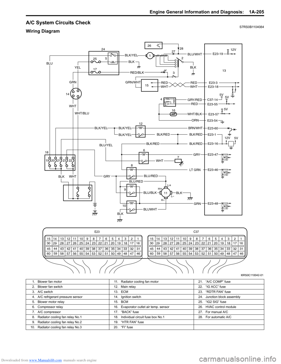
A/C System Circuits CheckS7RS0B1104084
Wiring Diagram
E23C37
34
1819
567
1011
17
20
47 46
495051
2122
52 16
25 9
24
14
29
55
57 54 53
59
60 58 2
262728
15
30
56 4832 31
34353637
40
42 39 38
44
45 43 41 331
1213
238
34
1819
567
1011
17
20
47 46
495051
2122
52 16
25 9
24
14
29
55
57 54 53
59
60 58 2
262728
15
30
56 4832 31
34353637
40
42 39 38
44
45 43 41 331
1213
238
BLK/REDBLK/RED
BLK/YELBLK/YEL
BLK/YEL
BRN/WHT
12V
5V
12
E23-1
E23-60
BLK/RED
LT GRN
BLK/REDE23-16
E23-46
L+
L–
H–
H
+
BLU/RED
BLK
BLUWHTBLK
BLU/BLK
BLU/RED
GRN
GRY
E23-48
8
11
2
3BLU/WHT
REDWHTREDWHTE23-3E23-18
E23-19
6
BLK
WHT
BLK 12V
E23-47 GRY
WHT
YELBLU
WHT
BLK/YEL
RED/BLK
GRN/WHT
WHT/BLU1
713
14
5V
5V
4
E23-55C37-14GRY/REDRED
E23-54ORN 5V
E23-57WHT/BLK16
9
10
25
17
5
24
15
22
BLU/YEL
23212019
GRN
BLK
18
26
28
27
I6RS0C110042-01
1. Blower fan motor 11. Radiator cooling fan motor 21. “A/C COMP” fuse
2. Blower fan switch 12. Main relay 22. “IG ACC” fuse
3. A/C switch 13. ECM 23. “RDTR FAN” fuse
4. A/C refrigerant pressure sensor 14. Ignition switch 24. Junction block assembly
5. Blower motor relay 15. BCM 25. “IG2 SIG” fuse
6. Compressor relay 16. Evaporator outlet air temp. sensor 26. HVAC control module
7. A/C compressor 17. “BACK” fuse 27. For manual A/C
8. Radiator cooling fan relay No.1 18. Individual circuit fuse box No.1 28. For automatic A/C
9. Radiator cooling fan relay No.2 19. “HTR FAN” fuse
10. Radiator cooling fan relay No.3 20. “FI” fuse
Page 256 of 1496
Downloaded from www.Manualslib.com manuals search engine 1A-206 Engine General Information and Diagnosis:
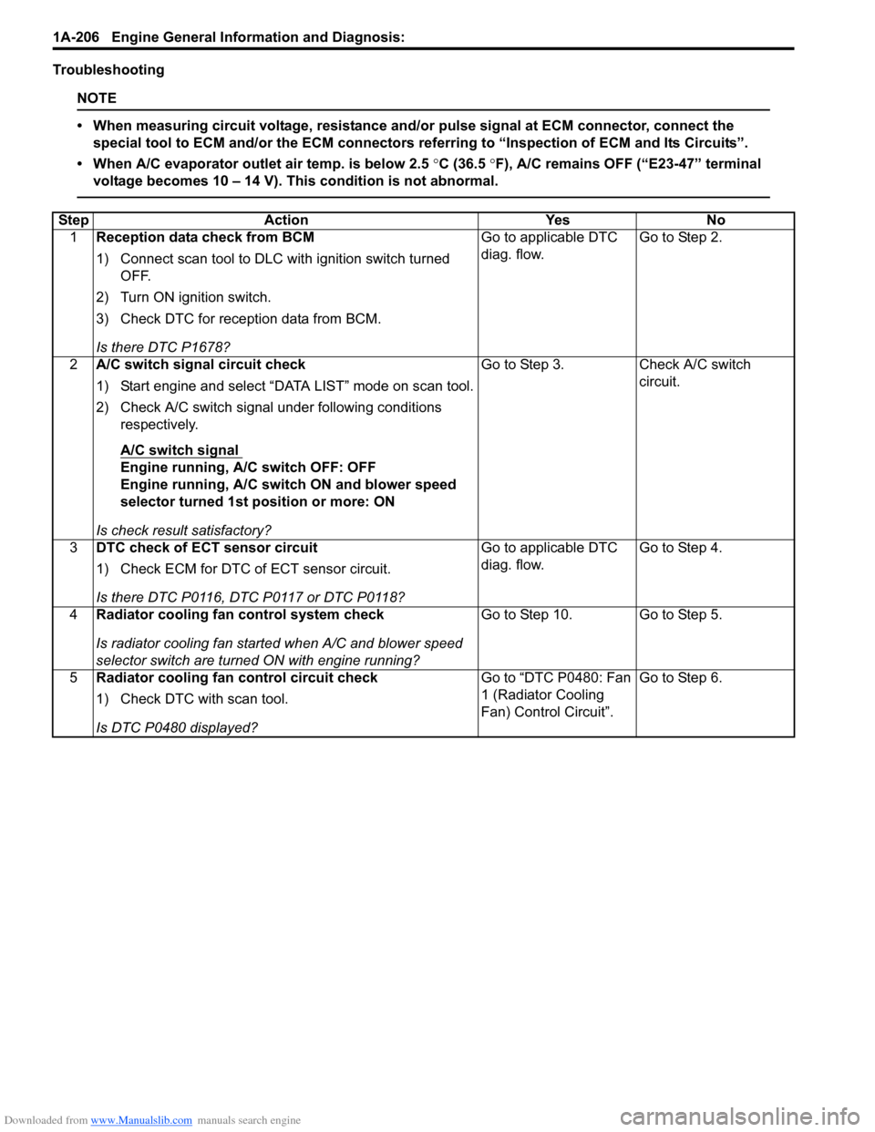
Troubleshooting
NOTE
• When measuring circuit voltage, resistance and/or pulse signal at ECM connector, connect the
special tool to ECM and/or the ECM connectors re ferring to “Inspection of ECM and Its Circuits”.
• When A/C evaporator outlet air temp. is below 2.5 °C (36.5 °F), A/C remains OFF (“E23-47” terminal
voltage becomes 10 – 14 V). This condition is not abnormal.
Step Action YesNo
1 Reception data check from BCM
1) Connect scan tool to DLC with ignition switch turned
OFF.
2) Turn ON ignition switch.
3) Check DTC for reception data from BCM.
Is there DTC P1678? Go to applicable DTC
diag. flow.
Go to Step 2.
2 A/C switch signal circuit check
1) Start engine and select “DATA LIST” mode on scan tool.
2) Check A/C switch signal under following conditions
respectively.
A/C switch signal
Engine running, A/C switch OFF: OFF
Engine running, A/C switch ON and blower speed
selector turned 1st position or more: ON
Is check result satisfactory? Go to Step 3. Check A/C switch
circuit.
3 DTC check of ECT sensor circuit
1) Check ECM for DTC of ECT sensor circuit.
Is there DTC P0116, DTC P0117 or DTC P0118? Go to applicable DTC
diag. flow.
Go to Step 4.
4 Radiator cooling fan control system check
Is radiator cooling fan started when A/C and blower speed
selector switch are turned ON with engine running? Go to Step 10. Go to Step 5.
5 Radiator cooling fan control circuit check
1) Check DTC with scan tool.
Is DTC P0480 displayed? Go to “DTC P0480: Fan
1 (Radiator Cooling
Fan) Control Circuit”.
Go to Step 6.