Page 837 of 1496

Downloaded from www.Manualslib.com manuals search engine Manual Transmission/Transaxle: 5B-23
Transaxle Right Case Disassembly and
Assembly
S7RS0B5206016
Disassembly1) Remove gear shift shaft, input shaft assembly and countershaft assembly referring to “Manual
Transaxle Assembly Disassembly and Reassembly”.
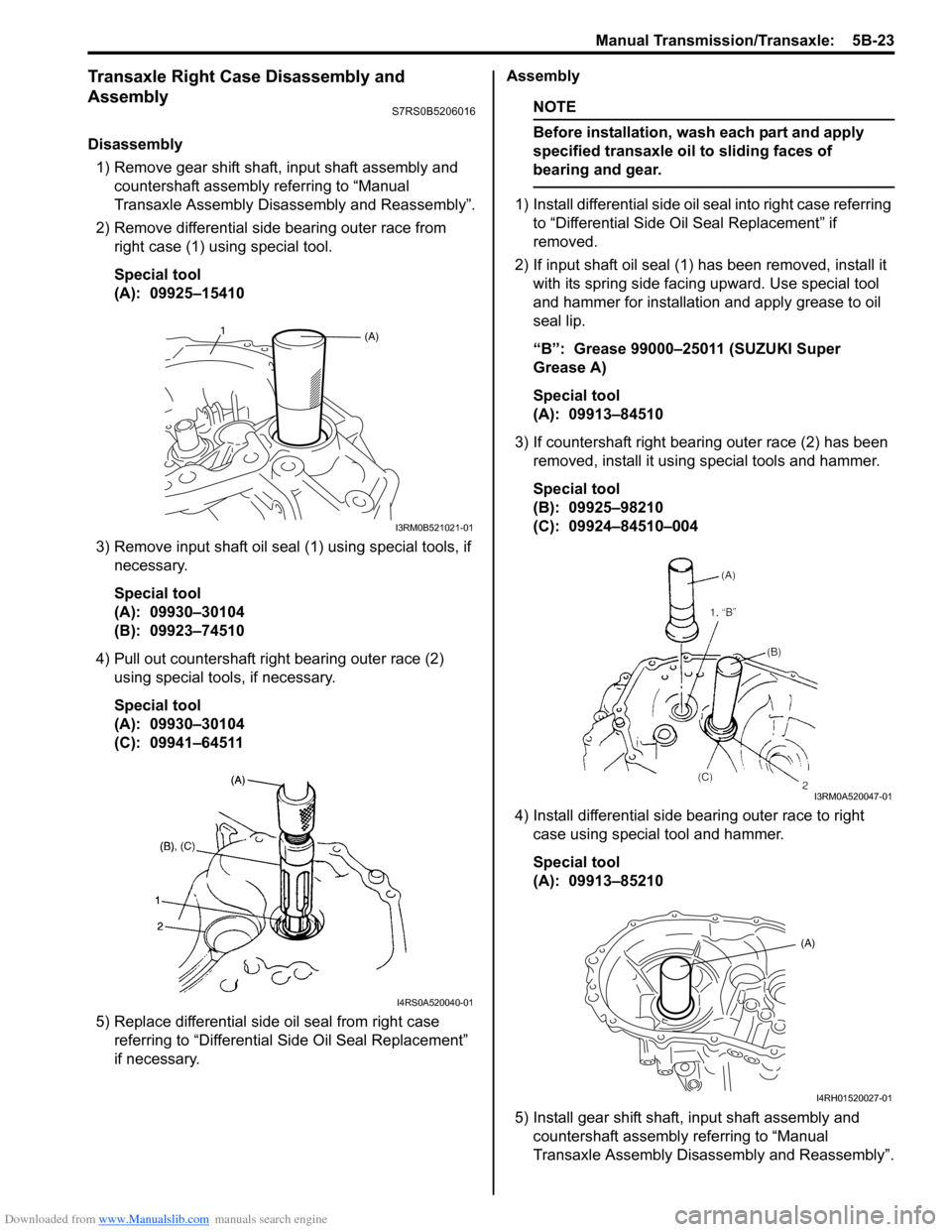
2) Remove differential side bearing outer race from right case (1) using special tool.
Special tool
(A): 09925–15410
3) Remove input shaft oil seal (1) using special tools, if necessary.
Special tool
(A): 09930–30104
(B): 09923–74510
4) Pull out countershaft right bearing outer race (2) using special tools, if necessary.
Special tool
(A): 09930–30104
(C): 09941–64511
5) Replace differential side oil seal from right case referring to “Differential Side Oil Seal Replacement”
if necessary. Assembly
NOTE
Before installation, wash each part and apply
specified transaxle oil to sliding faces of
bearing and gear.
1) Install differential side oil seal into right case referring
to “Differential Side O il Seal Replacement” if
removed.
2) If input shaft oil seal (1) has been removed, install it with its spring side facing upward. Use special tool
and hammer for installation and apply grease to oil
seal lip.
“B”: Grease 99000–25011 (SUZUKI Super
Grease A)
Special tool
(A): 09913–84510
3) If countershaft right bearing outer race (2) has been removed, install it using special tools and hammer.
Special tool
(B): 09925–98210
(C): 09924–84510–004
4) Install differential side bearing outer race to right case using special tool and hammer.
Special tool
(A): 09913–85210
5) Install gear shift shaft, input shaft assembly and countershaft assembly referring to “Manual
Transaxle Assembly Disassembly and Reassembly”.
(A)1
I3RM0B521021-01
I4RS0A520040-01
I3RM0A520047-01
(A)
I4RH01520027-01
Page 838 of 1496
Downloaded from www.Manualslib.com manuals search engine 5B-24 Manual Transmission/Transaxle:
Transaxle Left Case Disassembly and AssemblyS7RS0B5206017
Disassembly1) Replace differential side oil seal from left case referri ng to “Differential Side Oil Seal Replacement”, if necessary.
2) Remove input oil gutter (1) from left case, if necessary.
Assembly 1) If input oil gutter (1) has been removed, install it with bolt to which thread lock cement has been applied.
“A”: Thread lock cement 99000–32110 (Thread Lock Cement Super 1322)
Tightening torque
Oil gutter bolt (a): 10 N·m (1.0 kgf-m, 7.5 lb-ft)
2) If differential side oil seal is remov ed, install it to left case referring to “Differential Side Oil Seal Replacement”.
I4RH01520028-01
I3RM0A520048-01
Page 846 of 1496

Downloaded from www.Manualslib.com manuals search engine 5B-32 Manual Transmission/Transaxle:
5th and Reverse Gear Shift Shafts Disassembly
and Assembly
S7RS0B5206023
Disassembly
Disassemble component parts using special tool and
hammer.
Special tool
(A): 09922–85811
Assembly
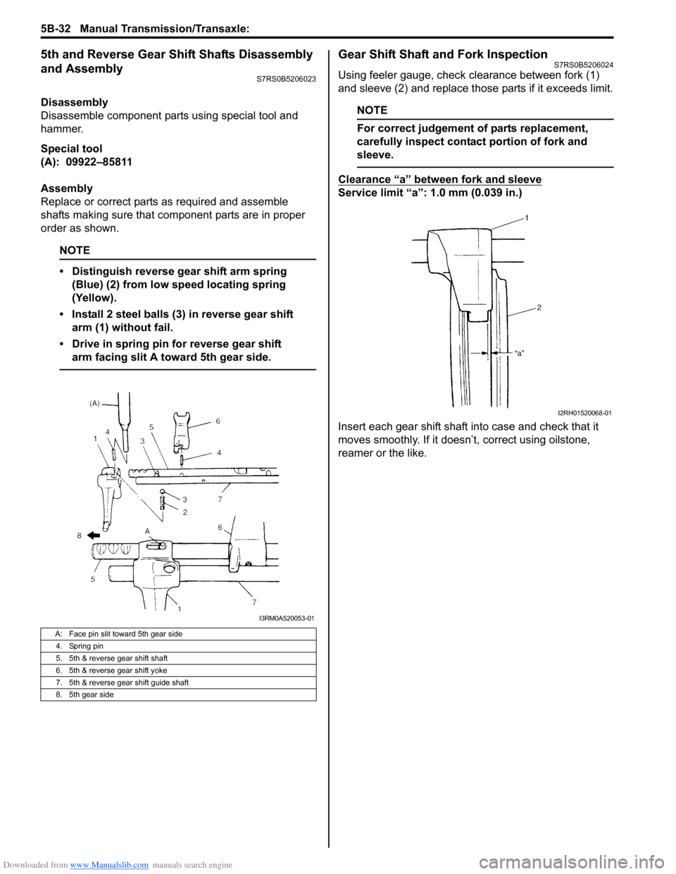
Replace or correct parts as required and assemble
shafts making sure that component parts are in proper
order as shown.
NOTE
• Distinguish reverse gear shift arm spring (Blue) (2) from low speed locating spring
(Yellow).
• Install 2 steel balls (3) in reverse gear shift arm (1) without fail.
• Drive in spring pin for reverse gear shift arm facing slit A toward 5th gear side.
Gear Shift Shaft and Fork InspectionS7RS0B5206024
Using feeler gauge, check clearance between fork (1)
and sleeve (2) and replace those parts if it exceeds limit.
NOTE
For correct judgement of parts replacement,
carefully inspect contact portion of fork and
sleeve.
Clearance “a” between fork and sleeve
Service limit “a”: 1.0 mm (0.039 in.)
Insert each gear shift shaft into case and check that it
moves smoothly. If it doesn’t, correct using oilstone,
reamer or the like.
A: Face pin slit toward 5th gear side
4. Spring pin
5. 5th & reverse gear shift shaft
6. 5th & reverse gear shift yoke
7. 5th & reverse gear shift guide shaft
8. 5th gear side
I3RM0A520053-01
I2RH01520068-01