2005 SUZUKI SWIFT Instrument meter
[x] Cancel search: Instrument meterPage 1168 of 1496

Downloaded from www.Manualslib.com manuals search engine 9-ii Table of Contents
List of Connectors ........................................... 9A-103
C Connector .................................................... 9A-103
D Connector (M16A engine) ........................... 9A-104
E Connector .................................................... 9A-104
G Connector .................................................... 9A-106
J Connector ..................................................... 9A-108
K Connector .................................................... 9A-109
L Connector..................................................... 9A-109
M Connector (SPORT model) ......................... 9A-111
O Connector .................................................... 9A-111
R Connector .................................................... 9A-111
Lighting Systems .................................... 9B-1
Component Location ........... ................................9B-1
Lighting System Component s Location............... 9B-1
Interior Light System Location............................. 9B-2
Diagnostic Information and Procedures ............ 9B-2 Headlight Symptom Diagnosis ............................ 9B-2
Headlight Leveling System Symptom Diagnosis (If Equipped) ..................................... 9B-2
Turn Signal and Hazard Warning Light Symptom Diagnosis .......................................... 9B-3
Clearance, Tail and License Plate Light Symptom Diagnosis .......................................... 9B-3
Back-Up Light Symptom Diagnosis..................... 9B-4
Brake Light Symptom Diagnosis ......................... 9B-4
Front Fog Light Symptom Diagnosis (If Equipped) .......................................................... 9B-4
Interior Light Symptom Diagnosis ....................... 9B-5
Repair Instructions ..............................................9B-5 Headlight Housing Removal and Installation ...... 9B-5
Headlight Bulb Replacemen t............................... 9B-6
Headlight Aiming Adjustment with Screen .......... 9B-6
Headlight Switch (in Lighting Switch) Removal and Installation ................................... 9B-8
Headlight Switch (in Lighting Switch) Inspection .......................................................... 9B-8
Hazard Warning Switch Removal and Installation ......................................................... 9B-8
Hazard Warning Switch Inspection ..................... 9B-9
Brake Light Switch Inspection ............................. 9B-9
Turn Signal Light Switch (in Lighting Switch) Removal and Installation ................................... 9B-9
Turn Signal Light Switch (in Lighting Switch) Inspection .......................................................... 9B-9
Turn Signal and Hazard Warning Relay Removal and Installation ................................... 9B-9
Turn Signal and Hazard Warning Relay Inspection ........................................................ 9B-10
License Light Removal and Installation............. 9B-10
Front Fog Light Removal and Installation (If Equipped) ........................................................ 9B-11
Front Fog Light Bulb Replacement (If Equipped) ........................................................ 9B-11
Front Fog Light Switch Inspection (If Equipped) ........................................................ 9B-11
Front Fog Light Relay Inspection (If Equipped) ........................................................ 9B-11
Front Fog Light Aiming Adjustment with Screen (If Equipped) ....................................... 9B-12 Headlight Leveling Switch Inspection (If
Equipped) ........................................................ 9B-13
Headlight Leveling Actuator Inspection (If Equipped) ........................................................ 9B-13
Instrumentation / Driver Info. / Horn ...... 9C-1
Precautions ...........................................................9C-1 Precautions in Diagnosing Troubles for Combination Meter ............................................9C-1
General Description .............................................9C-1 CAN Communication System Description...........9C-1
Auto Volume Co ntrol System Description (If
Equipped) ..........................................................9C-3
Schematic and Routing Diagram ........................9C-4 Combination Meter Circuit Diagram ....................9C-4
Component Location ............ ...............................9C-6
Audio System Component Location ....................9C-6
Diagnostic Information and Procedures ............9C-6 Speedometer and VSS Symp tom Diagnosis ......9C-6
Tachometer Symptom Diagnosis ........................9C-6
Engine Coolant Temperature (ECT) Meter Symptom Diagnosis ..........................................9C-7
Fuel Meter Symptom Diagnosis ..........................9C-7
Low Fuel Warning Light Symptom Diagnosis .....9C-7
Oil Pressure Warning Light Symptom Diagnosis ..........................................................9C-8
Brake and Parking Brake Warning Light Symptom Diagnosis ..........................................9C-8
Seat Belt Reminder Light Symptom Diagnosis (If Equipped)......................................................9C-8
A/T Shift Position Indicator Symptom Diagnosis (A/T Model).......................................9C-9
Charge Warning Light Sy mptom Diagnosis ........9C-9
Main Beam (High Beam) Indicator Symptom Diagnosis ..........................................................9C-9
Warning Buzzer Circuit Sy mptom Diagnosis ....9C-10
Cigarette Lighter Symptom Diagnosis (If Equipped) ........................................................9C-10
Horn Symptom Diagnosis .................................9C-10
Information Display Symptom Diagnosis (If Equipped) ........................................................9C-11
Clock Symptom Diagnosis (If Equipped)...........9C-12
Audio System Symptom Diagnosis (If Equipped) ........................................................9C-12
Remote Audio Control Switch Symptom Diagnosis (If Equipped) ...................................9C-13
Navigation Symptom Diagnosis (If Equipped)...9C-14
Repair Instructions ............ ................................9C-14
Ignition Switch Removal and Installation...........9C-14
Ignition Switch Inspection..................................9C-14
Combination Meter Removal and Installation ...9C-15
Fuel Level Sensor Removal and Installation .....9C-15
Fuel Level Sensor Inspection ............................9C-15
Oil Pressure Switch Remova l and Installation ..9C-15
Oil Pressure Switch Inspec tion .........................9C-16
Engine Coolant Temperature (ECT) Sensor Inspection ........................................................9C-16
Brake Fluid Level Switch Inspection .................9C-16
Parking Brake Switch Inspec tion.......................9C-16
Page 1189 of 1496
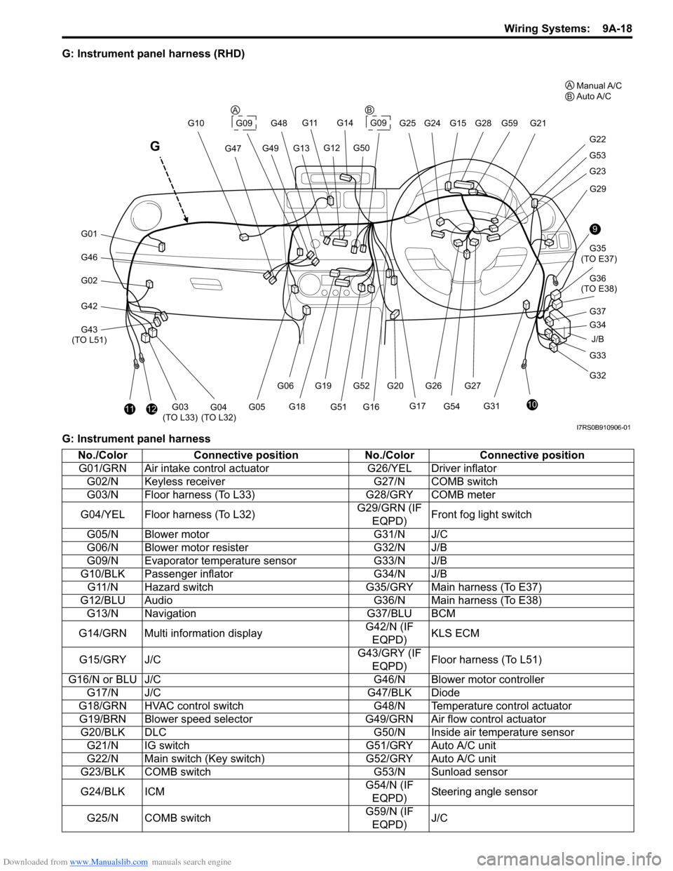
Downloaded from www.Manualslib.com manuals search engine Wiring Systems: 9A-18
G: Instrument panel harness (RHD)
G: Instrument panel harness
J/B
9
10
G33
G32 G34 G35
(TO E37)
G36
(TO E38)
G31 G29
G23
G53
G22
G21
G28G59
G20G52G27
G54
G261112G03
(TO L33)G04
(TO L32)
G46
G01
G02
G42
G43
(TO L51) G10
G47
G11
G13G49
G14
G09G25 G24G15
G12G50
G48
G17
G16G51
G19
G18
G06
G05
G
G09
G37
A
BManual A/C
Auto A/C
AB
I7RS0B910906-01
No./Color Connective position No./ColorConnective position
G01/GRN Air intake control ac tuatorG26/YEL Driver inflator
G02/N Keyless receiver G27/N COMB switch
G03/N Floor harness (To L33) G28/GRY COMB meter
G04/YEL Floor harness (To L32) G29/GRN (IF
EQPD) Front fog light switch
G05/N Blower motor G31/N J/C
G06/N Blower motor resister G32/N J/B
G09/N Evaporator temperature sensor G33/N J/B
G10/BLK Passenger inflator G34/N J/B
G11/N Hazard switch G35/GRY Main harness (To E37)
G12/BLU Audio G36/N Main harness (To E38)
G13/N Navigation G37/BLU BCM
G14/GRN Multi information display G42/N (IF
EQPD) KLS ECM
G15/GRY J/C G43/GRY (IF
EQPD) Floor harness (To L51)
G16/N or BLU J/C G46/N Blower motor controller
G17/N J/C G47/BLK Diode
G18/GRN HVAC control switch G48/N Temperature control actuator
G19/BRN Blower speed selector G49/GRN Air flow control actuator
G20/BLK DLC G50/N Inside air temperature sensor
G21/N IG switch G51/GRY Auto A/C unit
G22/N Main switch (Key switch) G52/GRY Auto A/C unit
G23/BLK COMB switch G53/N Sunload sensor
G24/BLK ICM G54/N (IF
EQPD) Steering angle sensor
G25/N COMB switch G59/N (IF
EQPD) J/C
Page 1190 of 1496
Downloaded from www.Manualslib.com manuals search engine 9A-19 Wiring Systems:
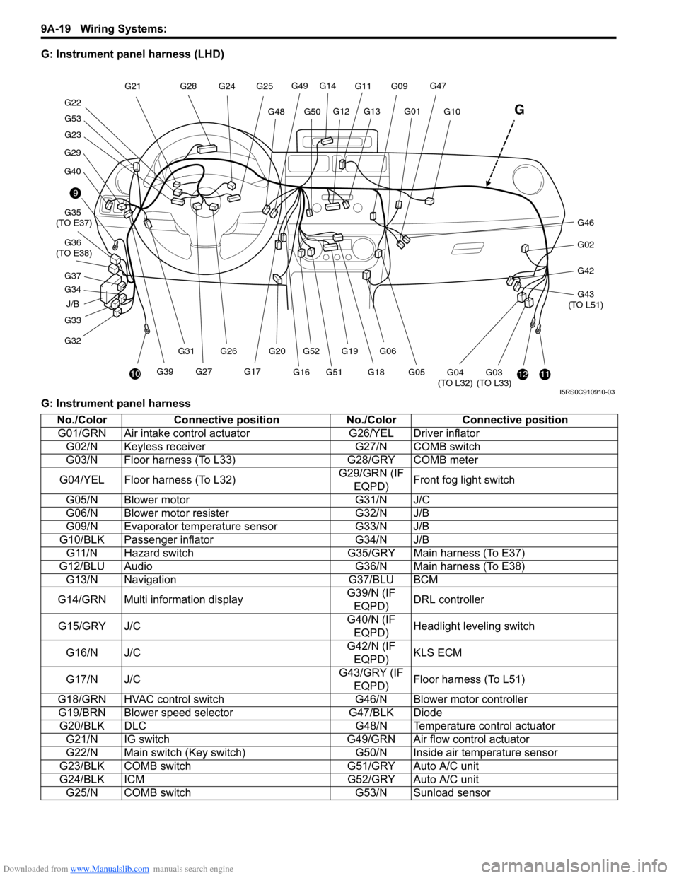
G: Instrument panel harness (LHD)
G: Instrument panel harness
J/B
9
10
G33
G32 G34 G35
(TO E37)
G36
(TO E38)
G29
G40
G23
G53
G22 G21
G28
G20G52
G27G39 G26
G31
1112G03
(TO L33)G04
(TO L32)
G46
G02
G42
G43
(TO L51)
G10
G47G11
G13G01
G14
G49
G50G48
G25
G24
G12
G17
G16G51G19
G18
G06
G05
G
G09
G37
I5RS0C910910-03
No./Color Connective position No./ColorConnective position
G01/GRN Air intake control ac tuatorG26/YEL Driver inflator
G02/N Keyless receiver G27/N COMB switch
G03/N Floor harness (To L33) G28/GRY COMB meter
G04/YEL Floor harness (To L32) G29/GRN (IF
EQPD) Front fog light switch
G05/N Blower motor G31/N J/C
G06/N Blower motor resister G32/N J/B
G09/N Evaporator temperature sensor G33/N J/B
G10/BLK Passenger inflator G34/N J/B
G11/N Hazard switch G35/GRY Main harness (To E37)
G12/BLU Audio G36/N Main harness (To E38)
G13/N Navigation G37/BLU BCM
G14/GRN Multi information display G39/N (IF
EQPD) DRL controller
G15/GRY J/C G40/N (IF
EQPD) Headlight leveling switch
G16/N J/C G42/N (IF
EQPD) KLS ECM
G17/N J/C G43/GRY (IF
EQPD) Floor harness (To L51)
G18/GRN HVAC control switch G46/N Blower motor controller
G19/BRN Blower speed selector G47/BLK Diode
G20/BLK DLC G48/N Temperature control actuator
G21/N IG switch G49/GRN Air flow control actuator
G22/N Main switch (Key switch) G50/N Inside air temperature sensor
G23/BLK COMB switch G51/GRY Auto A/C unit
G24/BLK ICM G52/GRY Auto A/C unit
G25/N COMB switch G53/N Sunload sensor
Page 1210 of 1496
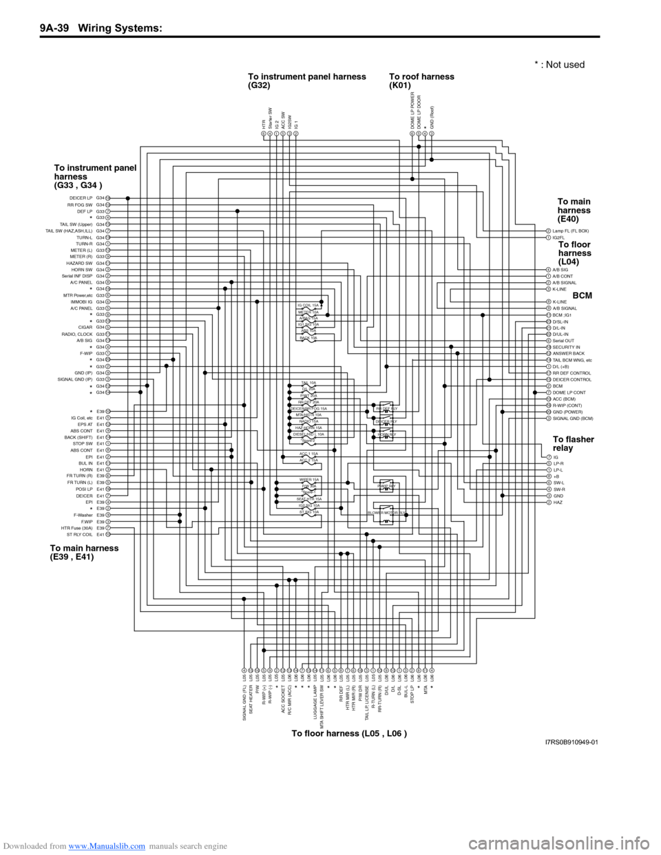
Downloaded from www.Manualslib.com manuals search engine 9A-39 Wiring Systems:
1IG2FL2
6
Lamp FL (FL BOX)
1A/B CONT4A/B SIG
3K-LINE2A/B SIGNAL
9A/B SIGNAL8K-LINE
2311BCM ;IG1
22D/UL-IN21D/L-IN D/SL-IN
18SECURITY IN6Serial OUT
14TAIL BCM WNG, etc12ANSWER BACK
17RR DEF CONTROL1D/L (+B)
2BCM15DEICER CONTROL
10ACC (BCM)7DOME LP CONT
20GND (POWER)16R-WIP (CONT)
3SIGNAL GND (BCM)
7IG
1LP-L5LP-R
8+B6SW-L
3GND4SW-R
2HAZ
DOME LP POWER5DOME LP DOOR4*3GND (Roof)6HTR4Starter SW1IG 25ACC SW3IG2SW2IG 1
18107G33415G347G3419G341G3412G339G3311G343G342G348G34166G336G345G33810511G3313G344G341G3320G342G339G343G3312G3414G34
10E395E4112E419E4114E411E418E412E4111E413E416E395E3916E417E414E392E399E393E397E3910E41
DEF LP
RR FOG SW DEICER LP
*TAIL SW (Upper)
TAIL SW (HAZ,ASH,ILL) TURN-L
TURN-R
METER (L)
METER (R)
HAZARD SW HORN SW
Serial INF DISP
A/C PANEL
*MTR Power,etc
IMMOBI IG
A/C PANEL
*
*
RADIO, CLOCK
A/B SIGCIGAR
*F-WIP*
*GND (IP)
SIGNAL GND (IP)
*
*
*
IG Coil, etc EPS AT
ABS CONT
BACK (SHIFT) STOP SW
ABS CONT EPI
BUL IN
HORN
FR TURN (R)
FR TURN (L) POSI LP
EPI
DEICER
*F-Washer
F.WIP
HTR Fuse (30A)
ST RLY COIL
4L0515L0516L055L059L05212L0513L0614L067L0615L0614L0511L056L065L068L057L056L0518L053L051L0510L059L0610L061L063L062L068L0611L064L06
SIGNAL GND (FL)
SEAT HEATER
P/W
R-WIP (+) R-WIP (-)*
ACC SOCKET
R/C MIR (ACC)
*
*
*
LUGGAGE LAMPMTA SHIFT LEVER SW
*
*
RR DEF
HTR MIR (L)
HTR MIR (R)
P/W DR
TAIL LP, LICENSE
R-TURN (L)
RR-TURN (R)
D/ULD/L
D-SL
BUL-L
STOP LP
MTA
*
*
IG COIL 15AMETER 10A A/BAG 15A
IG1 SIG 10A ABS 10A
BACK 10A
TAIL 10AD/L 20A
P/WT 20A
RR DEF 20A
DEICER/RR FOG 15A
MTA/HID R 10A
ACC 1 15A
ACC 2 15A
WIPER 15A P/W 30A
*Spare-1
SEAT HTR 15A IG2 SIG 10AST SIG 10A
HAZ-HORN 15A
DIESEL/HID L 10A *Spare-2 RR DEF RLY
DEICER RLY HORN RLY
P-WIP RLY
BLOWER MOTOR RLY
G34 G34
G33
G34
G33
G34 G33
L05
RADIO 15A
To instrument panel harness
(G32) To roof harness
(K01)
To instrument panel
harness
(G33 , G34 )
To main harness
(E39 , E41) To floor harness (L05 , L06 ) To main
harness
(E40)
BCM
To flasher
relay To floor
harness
(L04)
* : Not used
I7RS0B910949-01
Page 1296 of 1496
Downloaded from www.Manualslib.com manuals search engine 9C-1 Instrumentation / Driver Info. / Horn:
Body, Cab and Accessories
Instrumentation / Driver Info. / Horn
Precautions
Precautions in Diagnosing Troubles for Combination MeterS7RS0B9300001
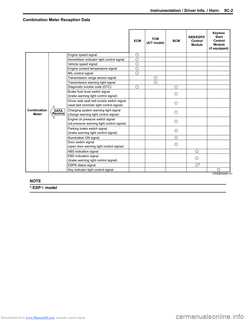
Combination meter uses signals (information) from each control module by CAN communication to control
speedometer, tachometer, engine coolant temp meter, warning light and indicator light (other than air bag warning
light, high beam indicator light, EPS warn ing light and turn signal indicator light). Therefore, check that no DTC is
detected in each module before performing combination me ter symptom diagnosis. If any DTC is detected, correct
trouble indicated by that DTC troubleshooting first.
General Description
CAN Communication System DescriptionS7RS0B9301001
Refer to “CAN Communication System Description in Section 1A” for Can communication system description.
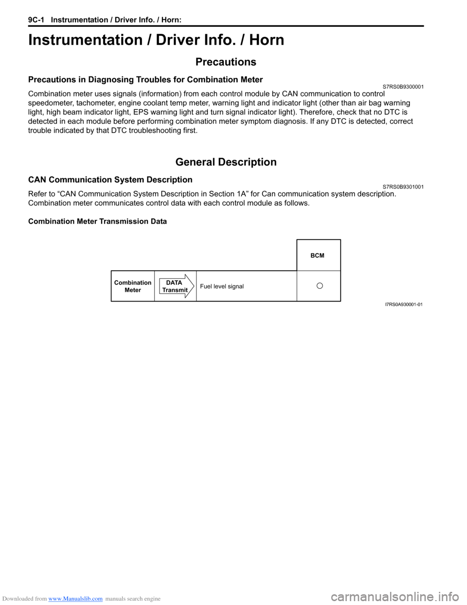
Combination meter communicates control data with each control module as follows.
Combination Meter Transmission Data
BCM
Combination Meter DATA
TransmitFuel level signal
I7RS0A930001-01
Page 1297 of 1496
Downloaded from www.Manualslib.com manuals search engine Instrumentation / Driver Info. / Horn: 9C-2
Combination Meter Reception Data
NOTE
*:ESP® model
ECM BCM
Keyless
Start
Control Module
(if equipped)
Combination Meter
TCM
(A/T model)
Engine speed signal
Immobilizer indicator light control signal
Vehicle speed signal
Engine coolant temperature signal
MIL control signal
Transmission range sensor signal
Transmission warning light signal
Diagnostic trouble code (DTC)
Brake fluid level switch signal
(brake warning light control signal)
Driver side seat belt buckle switch signal
(seat belt reminder light control signal)
Charging system warning light signal
(charge warning light control signal)
Engine oil pressure switch signal
(oil pressure warning light control signal)
Parking brake switch signal
(brake warning light control signal)
Illumination ON signal
Door switch signal
(open door warning light control signal)
ABS indication signal
EBD indication signal
(brake warning light control signal)
Key indicator light control signal ABS/ESP®
ControlModule
DATA
Receive
*
ESP® status signal
I7RS0B930001-01
Page 1299 of 1496
Downloaded from www.Manualslib.com manuals search engine Instrumentation / Driver Info. / Horn: 9C-4
Schematic and Routing Diagram
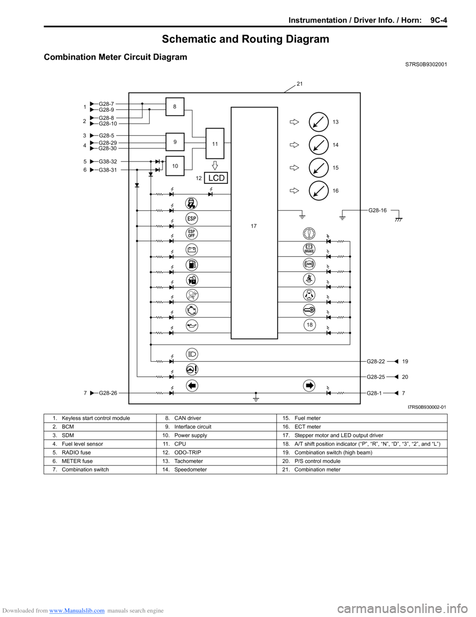
Combination Meter Circuit DiagramS7RS0B9302001
16
15
14
13
G28-5
5
6
3
G28-26
7
G28-2219
G28-2520
G28-17
12
10 11
21
9
17
G28-304G28-29
18
G28-16
G28-9
G28-10G28-8 G28-7
1
2 8
G38-31
G38-32
I7RS0B930002-01
1. Keyless start control module
8. CAN driver 15. Fuel meter
2. BCM 9. Interface circuit 16. ECT meter
3. SDM 10. Power supply 17. Stepper motor and LED output driver
4. Fuel level sensor 11. CPU 18. A/T shift position indicator (“P”, “R”, “N”, “D”, “3”, “2”, and “L”)
5. RADIO fuse 12. ODO-TRIP 19. Combination switch (high beam)
6. METER fuse 13. Tachometer 20. P/S control module
7. Combination switch 14. Speedometer 21. Combination meter
Page 1300 of 1496
Downloaded from www.Manualslib.com manuals search engine 9C-5 Instrumentation / Driver Info. / Horn:
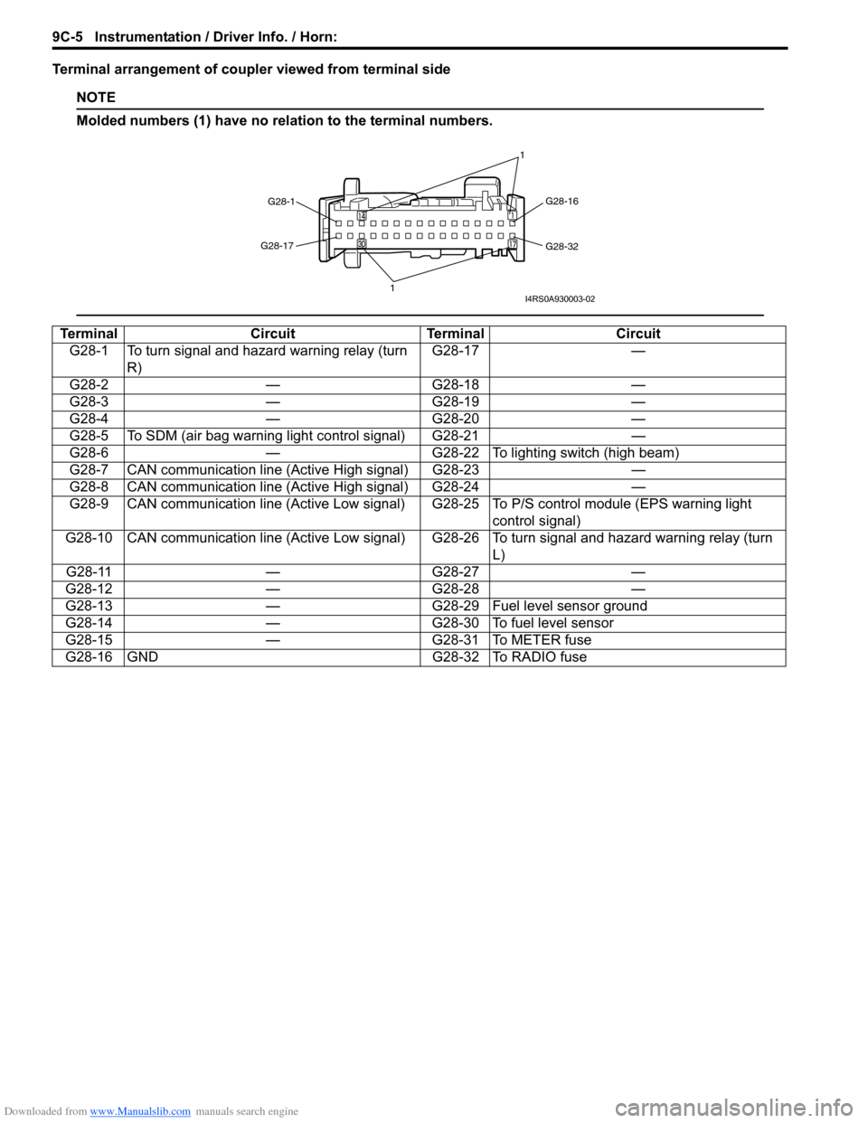
Terminal arrangement of coupler viewed from terminal side
NOTE
Molded numbers (1) have no relation to the terminal numbers.
TerminalCircuitTerminal Circuit
G28-1 To turn signal and hazard warning relay (turn R) G28-17
—
G28-2 —G28-18 —
G28-3 —G28-19 —
G28-4 —G28-20 —
G28-5 To SDM (air bag warning light control signal) G28-21 —
G28-6 —G28-22 To lighting switch (high beam)
G28-7 CAN communication line (Active High signal) G28-23 —
G28-8 CAN communication line (Active High signal) G28-24 —
G28-9 CAN communication line (Active Low signal) G 28-25 To P/S control module (EPS warning light
control signal)
G28-10 CAN communication line (Active Low signal) G28-26 To turn signal and hazard warning relay (turn L)
G28-11 —G28-27 —
G28-12 —G28-28 —
G28-13 —G28-29 Fuel level sensor ground
G28-14 —G28-30 To fuel level sensor
G28-15 —G28-31 To METER fuse
G28-16 GND G28-32 To RADIO fuse
G28-1 G28-16
G28-32
G28-17
1 1I4RS0A930003-02