Page 974 of 1496

Downloaded from www.Manualslib.com manuals search engine 7B-26 Air Conditioning System: Manual Type
Expansion Valve Removal and InstallationS7RS0B7216010
Removal1) Recover refrigerant fr om the A/C system with
recovery and recycling equipment referring to
“Recovery” in “Operation Procedure for Refrigerant
Charge”.
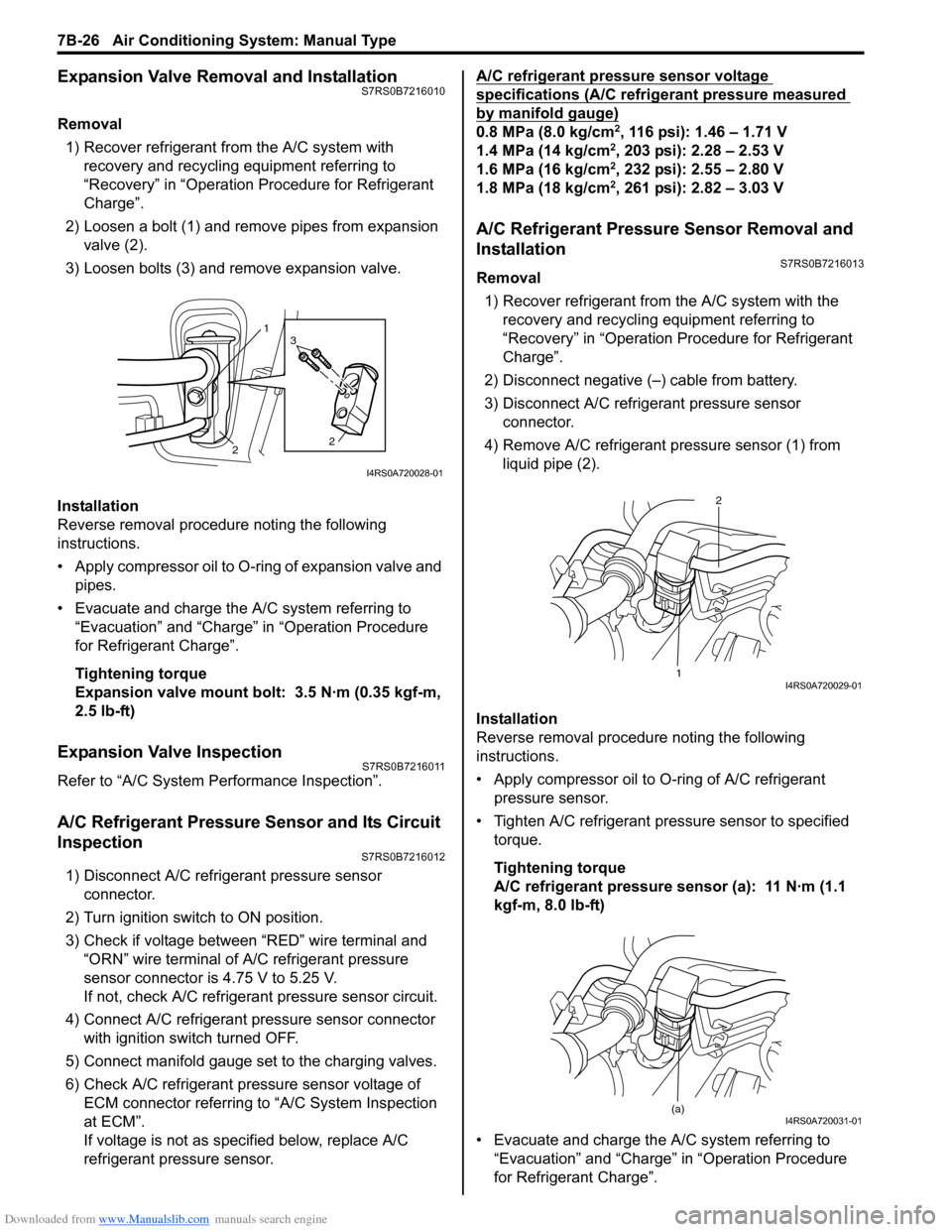
2) Loosen a bolt (1) and remove pipes from expansion valve (2).
3) Loosen bolts (3) and remove expansion valve.
Installation
Reverse removal procedure noting the following
instructions.
• Apply compressor oil to O-ring of expansion valve and pipes.
• Evacuate and charge the A/C system referring to “Evacuation” and “Charge” in “Operation Procedure
for Refrigerant Charge”.
Tightening torque
Expansion valve mount bolt: 3.5 N·m (0.35 kgf-m,
2.5 lb-ft)
Expansion Valve InspectionS7RS0B7216011
Refer to “A/C System Performance Inspection”.
A/C Refrigerant Pressure Sensor and Its Circuit
Inspection
S7RS0B7216012
1) Disconnect A/C refrigerant pressure sensor connector.
2) Turn ignition switch to ON position.
3) Check if voltage between “RED” wire terminal and “ORN” wire terminal of A/C refrigerant pressure
sensor connector is 4.75 V to 5.25 V.
If not, check A/C refrigerant pressure sensor circuit.
4) Connect A/C refrigerant pressure sensor connector with ignition switch turned OFF.
5) Connect manifold gauge set to the charging valves.
6) Check A/C refrigerant pressure sensor voltage of ECM connector referring to “A/C System Inspection
at ECM”.
If voltage is not as specified below, replace A/C
refrigerant pressure sensor. A/C refrigerant pressure sensor voltage
specifications (A/C refrigerant pressure measured
by manifold gauge)
0.8 MPa (8.0 kg/cm2, 116 psi): 1.46 – 1.71 V
1.4 MPa (14 kg/cm2, 203 psi): 2.28 – 2.53 V
1.6 MPa (16 kg/cm2, 232 psi): 2.55 – 2.80 V
1.8 MPa (18 kg/cm2, 261 psi): 2.82 – 3.03 V
A/C Refrigerant Pressure Sensor Removal and
Installation
S7RS0B7216013
Removal
1) Recover refrigerant from the A/C system with the recovery and recycling equipment referring to
“Recovery” in “Operation Procedure for Refrigerant
Charge”.
2) Disconnect negative (–) cable from battery.
3) Disconnect A/C refrigerant pressure sensor connector.
4) Remove A/C refrigerant pressure sensor (1) from liquid pipe (2).
Installation
Reverse removal procedure noting the following
instructions.
• Apply compressor oil to O-ring of A/C refrigerant
pressure sensor.
• Tighten A/C refrigerant pressure sensor to specified torque.
Tightening torque
A/C refrigerant pressure sensor (a): 11 N·m (1.1
kgf-m, 8.0 lb-ft)
• Evacuate and charge the A/C system referring to “Evacuation” and “Charge” in “Operation Procedure
for Refrigerant Charge”.
1
2 2
3
I4RS0A720028-01
1 2I4RS0A720029-01
(a)I4RS0A720031-01
Page 975 of 1496

Downloaded from www.Manualslib.com manuals search engine Air Conditioning System: Manual Type 7B-27
A/C Switch InspectionS7RS0B7216014
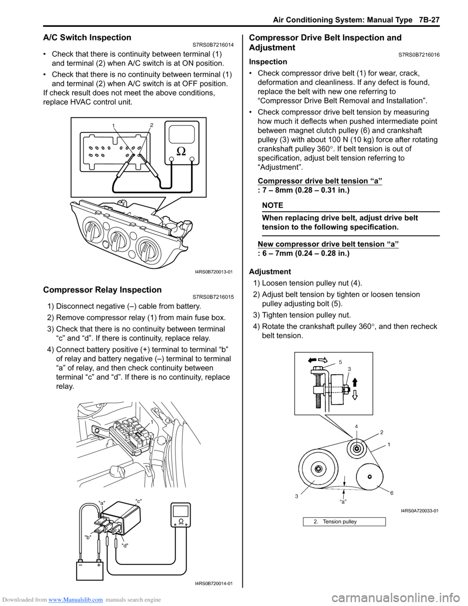
• Check that there is continuity between terminal (1) and terminal (2) when A/C s witch is at ON position.
• Check that there is no continuity between terminal (1) and terminal (2) when A/C s witch is at OFF position.
If check result does not meet the above conditions,
replace HVAC control unit.
Compressor Relay InspectionS7RS0B7216015
1) Disconnect negative (–) cable from battery.
2) Remove compressor relay (1) from main fuse box.
3) Check that there is no continuity between terminal “c” and “d”. If there is continuity, replace relay.
4) Connect battery positive (+ ) terminal to terminal “b”
of relay and battery negative (–) terminal to terminal
“a” of relay, and then check continuity between
terminal “c” and “d”. If there is no continuity, replace
relay.
Compressor Drive Belt Inspection and
Adjustment
S7RS0B7216016
Inspection
• Check compressor drive belt (1) for wear, crack, deformation and cleanliness. If any defect is found,
replace the belt with new one referring to
“Compressor Drive Belt Re moval and Installation”.
• Check compressor drive belt tension by measuring how much it deflects when pushed intermediate point
between magnet clutch pulley (6) and crankshaft
pulley (3) with about 100 N (10 kg) force after rotating
crankshaft pulley 360 °. If belt tension is out of
specification, adjust belt tension referring to
“Adjustment”.
Compressor drive belt tension
“a”
: 7 – 8mm (0.28 – 0.31 in.)
NOTE
When replacing drive belt, adjust drive belt
tension to the following specification.
New compressor dr ive belt tension “a”
: 6 – 7mm (0.24 – 0.28 in.)
Adjustment 1) Loosen tension pulley nut (4).
2) Adjust belt tension by ti ghten or loosen tension
pulley adjusting bolt (5).
3) Tighten tension pulley nut.
4) Rotate the crankshaft pulley 360 °, and then recheck
belt tension.
1 2
I4RS0B720013-01
"d"
"b" "a"
"c"
1
I4RS0B720014-01
2. Tension pulley
I4RS0A720033-01
Page 976 of 1496

Downloaded from www.Manualslib.com manuals search engine 7B-28 Air Conditioning System: Manual Type
Compressor Drive Belt Removal and
Installation
S7RS0B7216017
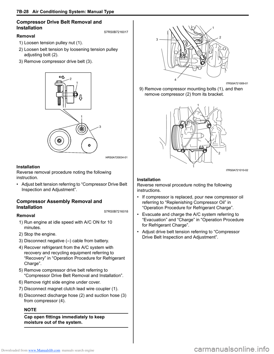
Removal1) Loosen tension pulley nut (1).
2) Loosen belt tension by loosening tension pulley adjusting bolt (2).
3) Remove compressor drive belt (3).
Installation
Reverse removal procedure noting the following
instruction.
• Adjust belt tension referring to “Compressor Drive Belt Inspection and Adjustment”.
Compressor Assembly Removal and
Installation
S7RS0B7216018
Removal
1) Run engine at idle speed with A/C ON for 10 minutes.
2) Stop the engine.
3) Disconnect negative (–) cable from battery.
4) Recover refrigerant fr om the A/C system with
recovery and recycling equipment referring to
“Recovery” in “Operation Procedure for Refrigerant
Charge”.
5) Remove compressor drive belt referring to “Compressor Drive Belt Re moval and Installation”.
6) Remove right side engine under cover.
7) Disconnect magnet clutch lead wire coupler (1).
8) Disconnect discharge hose (2) and suction hose (3) from compressor (4).
NOTE
Cap open fittings immediately to keep
moisture out of the system.
9) Remove compressor mounting bolts (1), and then remove compressor (2 ) from its bracket.
Installation
Reverse removal procedure noting the following
instructions.
• If compressor is replaced, pour new compressor oil referring to “Replenishi ng Compressor Oil” in
“Operation Procedure for Refrigerant Charge”.
• Evacuate and charge the A/C system referring to “Evacuation” and “Charge” in “Operation Procedure
for Refrigerant Charge”.
• Adjust drive belt tension referring to “Compressor Drive Belt Inspecti on and Adjustment”.
I4RS0A720034-01
3
4 2
1
I7RS0A721009-01
1
1 2
I7RS0A721010-02
Page 977 of 1496

Downloaded from www.Manualslib.com manuals search engine Air Conditioning System: Manual Type 7B-29
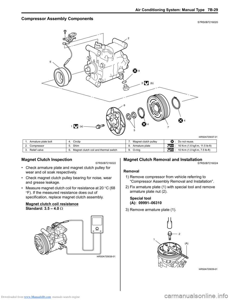
Compressor Assembly ComponentsS7RS0B7216020
Magnet Clutch InspectionS7RS0B7216022
• Check armature plate and magnet clutch pulley for wear and oil soak respectively.
• Check magnet clutch pulley bearing for noise, wear and grease leakage.
• Measure magnet clutch coil for resistance at 20 °C (68
° F). If the measured resistance does out of
specification, replace magnet clutch assembly.
Magnet clutch coil resistance
Standard: 3.5 – 4.0 Ω
Magnet Clutch Removal and InstallationS7RS0B7216024
Removal
1) Remove compressor from vehicle referring to “Compressor Assembly Re moval and Installation”.
2) Fix armature plate (1) with special tool and remove armature plate nut (2).
Special tool
(A): 09991–06310
3) Remove armature plate (1).
6
2
9
44
3 (b)
1 (a) 7
5
8
I4RS0A720037-01
1. Armature plate bolt
4. Circlip 7. Magnet clutch pulley: Do not reuse.
2. Compressor 5. Shim 8. Armature plate: 16 N⋅m (1.6 kgf-m, 11.5 lb-ft)
3. Relief valve 6. Magnet clutch coil and thermal switch 9. O-ring : 10 N⋅m (1.0 kgf-m, 7.5 lb-ft)
I4RS0A720038-01
2
1 (A)
I4RS0A720039-01