2005 SUZUKI SWIFT warning
[x] Cancel search: warningPage 722 of 1496

Downloaded from www.Manualslib.com manuals search engine 5A-78 Automatic Transmission/Transaxle:
DTC P2763: Torque Converter Clutch Pressure Control Solenoid Control Circuit HighS7RS0B5104043
Wiring Diagram
DTC Detecting Condition and Trouble Area
DTC Confirmation Procedure
WARNING!
• When performing a road test, select a place where there is no traffic or possibility of a traffic
accident and be very careful during testing to avoid occurrence of an accident.
• Road test should be carried out with 2 persons, a driver and a tester, on a level road.
1) Connect scan tool to DLC with ig nition switch OFF, if available.
2) Clear DTC in TCM memory.
3) Start engine.
4) Keep engine running at idle speed in “P” range for 10 seconds or more.
5) Check DTC.
DTC Troubleshooting
1. TCM 3. A/T
2. TCC lock-up pressure control solenoid valve [A]: Terminal arrangement of TCM connector (viewed from harness side)
DTC detecting conditionTrouble area
Voltage of TCC lock-up pressure control solenoid valve TCM
terminal is high although TCM is commanding TCC lock-up
pressure control sole noid to turn OFF. • TCC lock-up pressure contro
l solenoid valve circuit
shorted to ground
• Malfunction of TCC lock-up pressure control solenoid valve
•TCM
12V
C34-5
C34-3
WHT/BLU
WHT/BLK
3
1
2
53
C34C35
[A]
I4RS0A510019-01
Step
Action YesNo
1 Was “A/T System Check” performed? Go to Step 2.Go to “A/T System
Check”.
Page 724 of 1496

Downloaded from www.Manualslib.com manuals search engine 5A-80 Automatic Transmission/Transaxle:
DTC P2764: Torque Converter Clutch Circuit Pressure Control Solenoid Control Circuit LowS7RS0B5104044
Wiring Diagram
DTC Detecting Condition and Trouble Area
DTC Confirmation Procedure
WARNING!
• When performing a road test, select a place where there is no traffic or possibility of a traffic
accident and be very careful during testing to avoid occurrence of an accident.
• Road test should be carried out with 2 persons, a driver and a tester, on a level road.
1) Connect scan tool to DLC with ig nition switch OFF, if available.
2) Clear DTC in TCM memory.
3) Start engine.
4) Keep engine running at idle speed in “P” range for 20 seconds or more.
5) Check DTC.
DTC Troubleshooting
1. TCM 3. A/T
2. TCC pressure control solenoid valve [A]: Terminal arrangement of TCM connector (viewed from harness side)
DTC detecting condition Trouble area
Voltage of TCC lock-up pressure control solenoid valve TCM
terminal is low although TCM is commanding TCC lock-up
pressure control sole noid to turn ON. • TCC lock-up pressure contro
l solenoid valve circuit
shorted to ground
• Malfunction of TCC lock-up pressure control solenoid valve
•TCM
12V
C34-5
C34-3
WHT/BLU
WHT/BLK
3
1
2
53
C34C35
[A]
I4RS0A510019-01
Step
Action YesNo
1 Was “A/T System Check” performed? Go to Step 2.Go to “A/T System
Check”.
Page 750 of 1496
Downloaded from www.Manualslib.com manuals search engine 5A-106 Automatic Transmission/Transaxle:
Automatic Transaxle Unit Dismounting and
Remounting
S7RS0B5106031
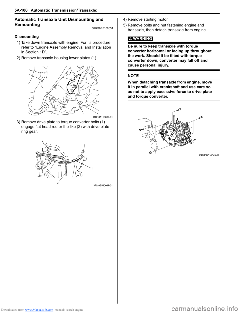
Dismounting1) Take down transaxle with engine. For its procedure, refer to “Engine Assembly Removal and Installation
in Section 1D”.
2) Remove transaxle housing lower plates (1).
3) Remove drive plate to torque converter bolts (1) engage flat head rod or the like (2) with drive plate
ring gear. 4) Remove starting motor.
5) Remove bolts and nut fastening engine and
transaxle, then detach transaxle from engine.WARNING!
Be sure to keep transaxle with torque
converter horizontal or facing up throughout
the work. Should it be tilted with torque
converter down, converter may fall off and
cause personal injury.
NOTE
When detaching transaxle from engine, move
it in parallel with cranks haft and use care so
as not to apply excessive force to drive plate
and torque converter.
1I4RS0A150004-01
I3RM0B510047-01
I3RM0B510049-01
Page 751 of 1496
Downloaded from www.Manualslib.com manuals search engine Automatic Transmission/Transaxle: 5A-107
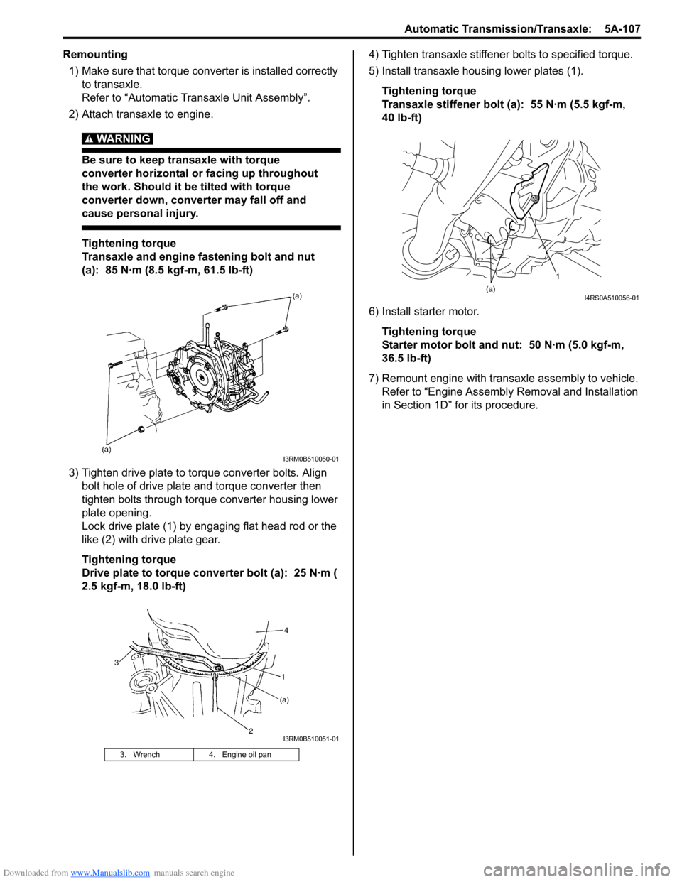
Remounting1) Make sure that torque converter is installed correctly to transaxle.
Refer to “Automatic Transaxle Unit Assembly”.
2) Attach transaxle to engine.
WARNING!
Be sure to keep transaxle with torque
converter horizontal or facing up throughout
the work. Should it be tilted with torque
converter down, converter may fall off and
cause personal injury.
Tightening torque
Transaxle and engine fastening bolt and nut
(a): 85 N·m (8.5 kgf-m, 61.5 lb-ft)
3) Tighten drive plate to torque converter bolts. Align bolt hole of drive plate and torque converter then
tighten bolts through torque converter housing lower
plate opening.
Lock drive plate (1) by engaging flat head rod or the
like (2) with drive plate gear.
Tightening torque
Drive plate to torque converter bolt (a): 25 N·m (
2.5 kgf-m, 18.0 lb-ft) 4) Tighten transaxle stiffener bolts to specified torque.
5) Install transaxle housing lower plates (1).
Tightening torque
Transaxle stiffener bolt (a): 55 N·m (5.5 kgf-m,
40 lb-ft)
6) Install starter motor. Tightening torque
Starter motor bolt and nut: 50 N·m (5.0 kgf-m,
36.5 lb-ft)
7) Remount engine with transaxle assembly to vehicle. Refer to “Engine Assembly Removal and Installation
in Section 1D” for its procedure.
3. Wrench 4. Engine oil pan
I3RM0B510050-01
I3RM0B510051-01
1
(a)
I4RS0A510056-01
Page 786 of 1496
Downloaded from www.Manualslib.com manuals search engine 5A-142 Automatic Transmission/Transaxle:
Differential Assembly Disassembly and
Reassembly
S7RS0B5106055
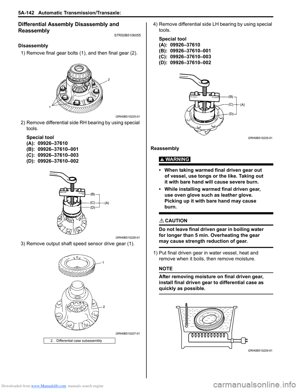
Disassembly1) Remove final gear bolts (1), and then final gear (2).
2) Remove differential side RH bearing by using special tools.
Special tool
(A): 09926–37610
(B): 09926–37610–001
(C): 09926–37610–003
(D): 09926–37610–002
3) Remove output shaft speed sensor drive gear (1). 4) Remove differential side LH bearing by using special
tools.
Special tool
(A): 09926–37610
(B): 09926–37610–001
(C): 09926–37610–003
(D): 09926–37610–002
Reassembly
WARNING!
• When taking warmed final driven gear out of vessel, use tongs or the like. Taking out
it with bare hand will cause severe burn.
• While installing warme d final driven gear,
use oven glove such as leather glove.
Picking up it with bare hand may cause
burn.
CAUTION!
Do not leave final driven gear in boiling water
for longer than 5 min. Overheating the gear
may cause strength reduction of gear.
1) Put final driven gear in water vessel, heat and remove when it boils, then remove moisture.
NOTE
After removing moisture on final driven gear,
install final driven gear to differential case as
quickly as possible.
2. Differential case subassembly
I2RH0B510225-01
I2RH0B510226-01
I2RH0B510227-01
I2RH0B510228-01
I2RH0B510229-01
Page 867 of 1496

Downloaded from www.Manualslib.com manuals search engine Table of Contents 6- i
6
Section 6
CONTENTS
Steering
Precautions ................................................. 6-1
Precautions............................................................. 6-1
Precautions on Steering........................................ 6-1
Steering General Diagnosi s.................... 6A-1
Precautions........................................................... 6A-1
Precautions for Steering Diagnosis ..................... 6A-1
Diagnostic Information and Procedures ............ 6A-2 Steering Symptom Diagnosis .............................. 6A-2
Steering Wheel and Column ................... 6B-1
Precautions........................................................... 6B-1
Service Precautions of Steering Wheel and Column.............................................................. 6B-1
General Description ............................................. 6B-1 Steering Wheel and Column Construction .......... 6B-1
Diagnostic Information and Procedures ............ 6B-2 Checking Steering Column for Accident Damage ............................................................ 6B-2
Repair Instructions .............................................. 6B-3 Steering Wheel and Column Construction .......... 6B-3
Steering Wheel Removal and Installation ........... 6B-4
Contact Coil Cable Assembly Removal and Installation ......................................................... 6B-5
Centering Contact Coil Cable Assembly ............. 6B-6
Contact Coil Cable Assembly Inspection ............ 6B-6
Steering Angle Sensor Removal and Installation ......................................................... 6B-6
Steering Angle Sensor Inspection ....................... 6B-6
Steering Column Removal and Installation ......... 6B-7
Steering Column Inspecti on ................................ 6B-8
Ignition Switch Cylinder Assembly Removal and Installation (Non- Keyless Start Model)...... 6B-9
Steering Lock Assembly (Ignition Switch) Removal and Installation................................... 6B-9
Steering Lower Shaft Removal and Installation ....................................................... 6B-10
Specifications ..................................................... 6B-11
Tightening Torque Specifications ...................... 6B-11
Special Tools and Equipmen t ........................... 6B-11
Special Tool ...................................................... 6B-11
Power Assisted Steering System........... 6C-1
Precautions........................................................... 6C-1 Steering System Note .........................................6C-1
Precautions in Diagnosing Troubles ...................6C-1
General Description .............................................6C-2 P/S System Description ......................................6C-2
EPS Diagnosis General Descr iption ...................6C-3
On-Board Diagnostic System Description ...........6C-3
Schematic and Routing Diagram ........................6C-4 EPS System Wiring Circuit Diagram ...................6C-4
Diagnostic Information and Procedures ............6C-5 EPS System Check .............. ...............................6C-5
“EPS” Warning Light Check . ...............................6C-8
DTC Check..........................................................6C-8
DTC Clearance ...................................................6C-9
DTC Table ...........................................................6C-9
Scan Tool Data .................................................6C-11
Visual Inspection ...............................................6C-12
P/S System Symptom Diagnosis ......................6C-12
Serial Data Link Circuit Check ..........................6C-13
“EPS” Warning Light Do es Not Come ON with
Ignition Switch Turn ed ON before Engine
Starts ...............................................................6C-15
“EPS” Warning Light Remains ON Steady after Engine Starts ..........................................6C-16
DTC C1113: Steering Torque Sensor (Main and Sub) Circuit Correlation ............................6C-17
DTC C1114: Steering Torque Sensor Reference Power Supply Circuit .....................6C-19
DTC C1117: Steering Torque Sensor Failure Signal Circuit Low ...........................................6C-21
DTC C1118: Steering Torque Sensor Failure Signal Circuit High...........................................6C-22
DTC C1119: Steering Torque Sensor Power Supply Circuit ..................................................6C-24
DTC C1121 / C1123 / C1124: VSS Circuit
Failure .............................................................6C-26
DTC C1122: Engine Speed Signal....................6C-28
DTC C1141 / C1142 / C1143 / C1145: P/S Motor Circuit Failure ........................................6C-30
DTC C1153: P/S Control Module Power Supply Circuit Voltage Low .............................6C-32
DTC C1155: P/S Control Module Failure ..........6C-33
P/S Control Module Power Supply and Ground Circuit Check ......................................6C-34
Inspection of P/S Control Module and Its Circuits ............................................................6C-35
Page 869 of 1496
Downloaded from www.Manualslib.com manuals search engine Precautions: 6-1
Steeri ng
Precautions
Precautions
Precautions on SteeringS7RS0B6000001
Air Bag Warning
Refer to “Air Bag Warning in Section 00”.
Air Bag System Service Warning
Refer to “Air Bag System Service Warning in Section 00”.
Precautions for Steering Diagnosis
Refer to “Precautions for Steering Diagnosis in Section 6A”.
Service Precautions of Steering Wheel and Column
Refer to “Service Precautions of Steering Wheel and Column in Section 6B”.
P/S System Note
Refer to “Steering System Note in Section 6C”.
Page 878 of 1496
Downloaded from www.Manualslib.com manuals search engine 6B-7 Steering Wheel and Column:
Steering Column Removal and InstallationS7RS0B6206006
CAUTION!
Once the steering column is removed from
the vehicle, the column is extremely
susceptible to damage.
• Dropping the column assembly on its end could collapse the steering shaft or loosen
the plastic shear pins which maintain
column length.
• Leaning on the column assembly could cause it to bend or deform.
Any of the damage could impair the column’s
collapsible design.
Steering column mounting nuts should not
be loosened with steering shaft joint upper
side bolt tightened as this could cause
damage to shaft joint bearing.
NOTE
When servicing steering column or any
column-mounted component, remove
steering wheel. But when removing steering
column simply to gain access to instrument
panel components, leave steering wheel
installed on steering column.
Removal
WARNING!
Never rest a steering column assembly on
the steering wheel with the air bag (inflator)
module face down and column vertical.
Otherwise, personal injury may result.
1) Disconnect negative (–) cable at battery.
2) Disable air bag system. Re fer to “Disabling Air Bag
System in Section 8B”.
3) Remove steering wheel and contact coil cable assembly referring to “S teering Wheel Removal and
Installation” and “Contact Coil Cable Assembly
Removal and Installation”.
4) Detach lighting switch and wiper switch from steering column.
5) Remove immobilizer cont rol module from steering
column, referring to “Immo bilizer Control Module
(ICM) Removal and Installation in Section 10C”.
6) Remove steering column hole cover.
7) Remove steering joint cover.
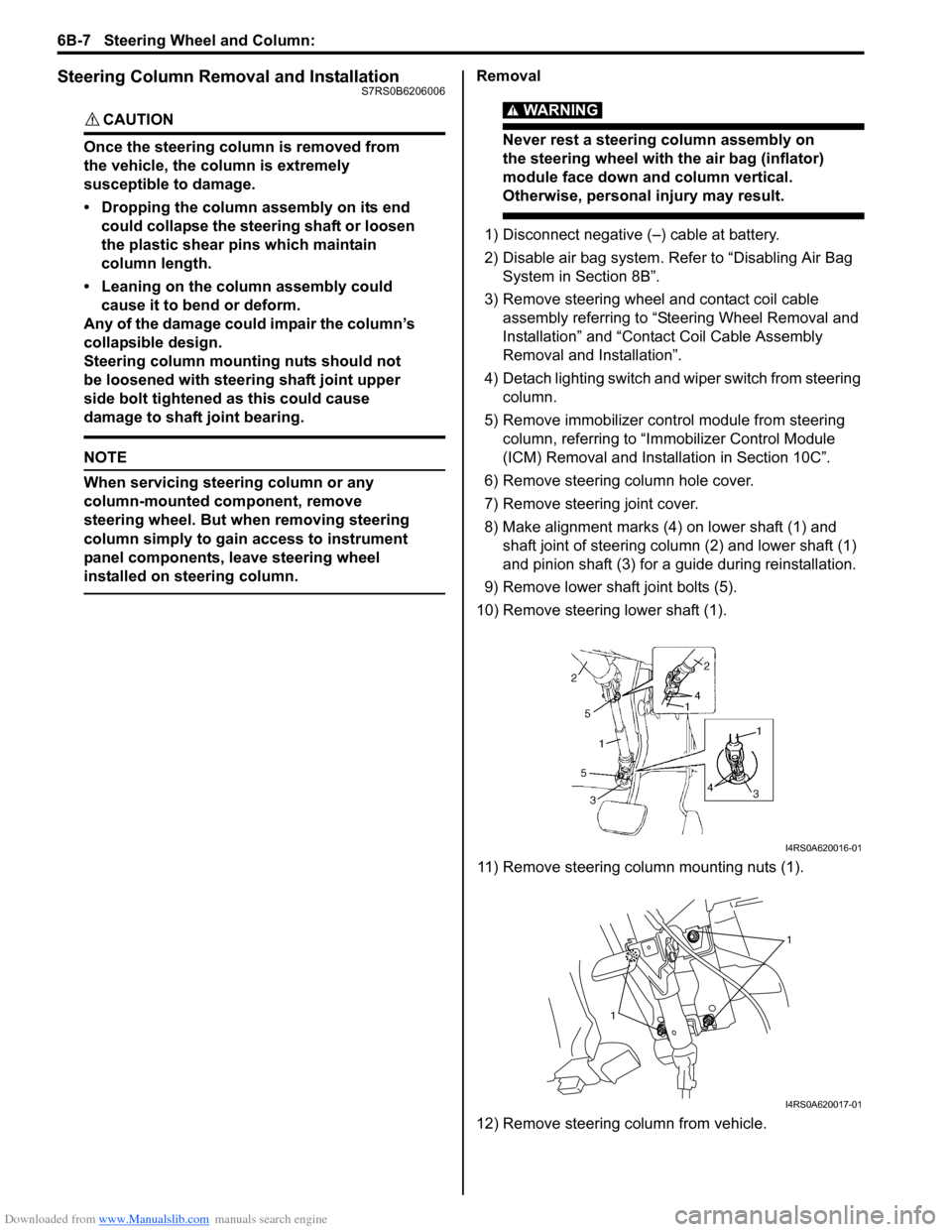
8) Make alignment marks (4) on lower shaft (1) and shaft joint of steering column (2) and lower shaft (1)
and pinion shaft (3) for a guide during reinstallation.
9) Remove lower shaf t joint bolts (5).
10) Remove steering lower shaft (1).
11) Remove steering column mounting nuts (1).
12) Remove steering column from vehicle.
I4RS0A620016-01
1
1
I4RS0A620017-01