2005 SUZUKI SWIFT Connectors
[x] Cancel search: ConnectorsPage 627 of 1496
Downloaded from www.Manualslib.com manuals search engine Electronic Stability Program: 4F-53
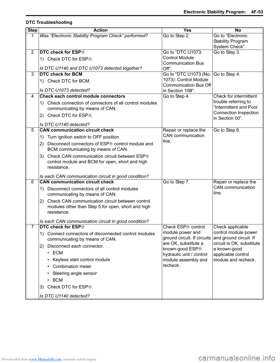
DTC TroubleshootingStep Action Yes No 1 Was “Electronic Stability Pr ogram Check” performed? Go to Step 2. Go to “Electronic
Stability Program
System Check”.
2 DTC check for ESP®
1) Check DTC for ESP ®.
Is DTC U1140 and DTC U1073 detected together? Go to “DTC U1073:
Control Module
Communication Bus
Off”.Go to Step 3.
3 DTC check for BCM
1) Check DTC for BCM.
Is DTC U1073 detected? Go to “DTC U1073 (No.
1073): Control Module
Communication Bus Off
in Section 10B”.Go to Step 4.
4 Check each control module connectors
1) Check connection of connectors of all control modules
communicating by means of CAN.
2) Check DTC for ESP ®.
Is DTC U1140 detected? Go to Step 4. Check for intermittent
trouble referring to
“Intermittent and Poor
Connection Inspection
in Section 00”.
5 CAN communication circuit check
1) Turn ignition switch to OFF position.
2) Disconnect connectors of ESP ® control module and
BCM communicating by means of CAN.
3) Check CAN communication circuit between ESP®
control module and BCM for open, short and high
resistance.
Is each CAN communication circuit in good condition? Repair or replace the
CAN communication
line.
Go to Step 6.
6 CAN communication circuit check
1) Disconnect connectors of all control modules
communicating by means of CAN.
2) Check CAN communication circuit between control modules other than Step 5 for open, short and high
resistance.
Is each CAN communication circuit in good condition? Go to Step 7. Repair or replace the
CAN communication
line.
7 DTC check for ESP®
1) Connect connectors of disconnected control modules
communicating by means of CAN.
2) Disconnect each connector. •ECM
• Keyless start control module
• Combination meter
• Steering angle sensor
•BCM
3) Check DTC for ESP ®.
Is DTC U1140 detected? Check ESP
® control
module power and
ground circuit. If circuits
are OK, substitute a
known-good ESP ®
hydraulic unit / control
module assembly and
recheck. Check applicable
control module power
and ground circuit. If
circuit is OK, substitute
a known-good
applicable control
module and recheck.
Page 662 of 1496

Downloaded from www.Manualslib.com manuals search engine 5A-18 Automatic Transmission/Transaxle:
Visual InspectionS7RS0B5104002
Visually check the following parts and systems.
Malfunction Indicator Lamp (MIL) CheckS7RS0B5104003
Refer to the same item in “Malfunction Indicator Lam p (MIL) Check in Section 1A” for checking procedure.
Transmission Warning Light CheckS7RS0B5104004
1) Turn ignition switch ON.
2) Check that transmission warning light lights for about 2 – 4 sec. and then goes OFF.
If anything faulty is found, advance “Transmission Warn ing Light Circuit Check – Light Does Not Come “ON” at
Ignition Switch ON” or “Transmission Warning Light Circu it Check – Light Remains “ON” at Ignition Switch ON”.
Inspection item Referring
• A/T fluid ----- level, leakage, color “Automatic Transaxle Fluid Level Inspection in Section 0B”
• A/T fluid hoses ----- disconnection, looseness, deterioration “A/T Fluid Cooler Hoses Replacement”
• A/T select cable ----- installation “S elect Cable Removal and Installation”
• Engine oil ----- level, leakage “Engine Oil and Filter Change in Section 0B”
• Engine coolant ----- level, leakage “Engine Coolant Change in Section 0B”
• Engine mountings ----- play, looseness, damage “Engine Assembly Removal and Installation in Section 1D”
• Suspension ----- play, looseness “Suspension, Wheels and Tires Symptom Diagnosis in Section 2A”
• Drive shafts ----- damage “Front Drive Shaft Assembly On-Vehicle Inspection in Section 3A”
• Battery ----- indicator condition, corrosion of terminal “Battery Inspection in Section 1J”
• Connectors of electric wire harness ----- disconnection, friction “Electronic Shift Control System Components
Location”
• Fuses ----- burning
• Parts ----- installation, damage
• Bolts ----- looseness
• Other parts that can be checked visually
Also check the following items at engine start, if possible.
• Transmission warning light (if equipped) ----- Operation “Transmission Warning Light Check”
• Malfunction indicator lamp ----- Operation “Malfunction Indicator Lamp (MIL) Check”
• Charge warning lamp ----- Operation “Generator Symptom Diagnosis in Section 1J”
• Engine oil pressure warning lamp ----- Operation “Oil Pressure Warning Ligh t Symptom Diagnosis in
Section 9C”
• Engine coolant temp. meter ----- Operation “Engine Coolant Temperature (ECT) Meter
Symptom Diagnosis in Section 9C”
• Other parts that can be checked visually
I4RS0A510008-01
Page 694 of 1496

Downloaded from www.Manualslib.com manuals search engine 5A-50 Automatic Transmission/Transaxle:
DTC Confirmation Procedure
WARNING!
• When performing a road test, select a place where there is no traffic or possibility of a traffic
accident and be very careful during testing to avoid occurrence of an accident.
• Road test should be carried out with 2 persons, a driver and a tester, on a level road.
1) Connect scan tool to DLC with ig nition switch OFF, if available.
2) Clear DTC in TCM memory and start engine.
3) Start vehicle and increase vehicle speed to about 40 km/h (25 mile/h) for 20 minutes or more.
4) Stop vehicle and check DTC.
DTC Troubleshooting Step Action Yes No 1 Was “A/T System Check” performed? Go to Step 2. Go to “A/T System
Check”.
2 Check transmission fluid temperature circuit for open
1) Turn ignition switch OFF.
2) Disconnect TCM connectors from TCM.
3) Check for proper connection to transmission fluid
temperature sensor at terminals “C34-11” and “C34-12”.
4) If OK, check continuity between terminals “C34-11” and “C34-12” of disconnected harness side TCM connector.
Is continuity indicated? Go to Step 3. “LT GRN” or “ORN”
circuit open.
3 Check transmission fluid temperature circuit for IG
short
1) Cool down A/T fluid te mperature under ambient
temperature.
2) Connect TCM connectors to TCM with ignition switch OFF.
3) Turn ignition switch ON.
4) Measure voltage between terminal “C34-11” of TCM connector and ground.
Is it 4.6 V or more? “LT GRN” circuit shorted
to power circuit.
If circuit is OK, go to
St ep 4 .
Intermittent trouble or
faulty TCM.
Check for intermittent
referring to “Intermittent
and Poor Connection
Inspection in Section
00”.
If OK, substitute a
known-good TCM and
recheck.
4 Inspect transmission fluid temperature sensor
1) Inspect transmission fluid temperature sensor referring
to “Transmission Fluid Temperature Sensor Inspection”.
Is result satisfactory? Intermittent trouble or
faulty TCM.
Check for intermittent
referring to “Intermittent
and Poor Connection
Inspection in Section
00”.
If OK, substitute a
known-good TCM and
recheck.Replace transmission
fluid temperature
sensor.
Page 695 of 1496
Downloaded from www.Manualslib.com manuals search engine Automatic Transmission/Transaxle: 5A-51
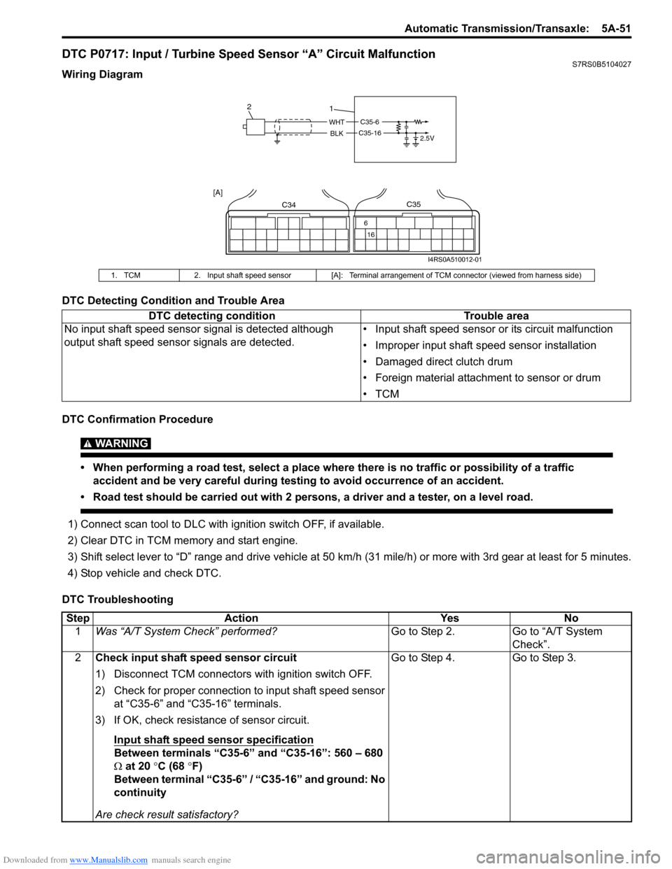
DTC P0717: Input / Turbine Speed Sensor “A” Circuit MalfunctionS7RS0B5104027
Wiring Diagram
DTC Detecting Condition and Trouble Area
DTC Confirmation Procedure
WARNING!
• When performing a road test, select a place where there is no traffic or possibility of a traffic accident and be very careful during testing to avoid occurrence of an accident.
• Road test should be carried out with 2 persons, a driver and a tester, on a level road.
1) Connect scan tool to DLC with ig nition switch OFF, if available.
2) Clear DTC in TCM memory and start engine.
3) Shift select lever to “D” range and drive vehicle at 50 km /h (31 mile/h) or more with 3rd gear at least for 5 minutes.
4) Stop vehicle and check DTC.
DTC Troubleshooting
1. TCM 2. Input shaft speed sensor [A]: Terminal arrangement of TCM connector (viewed from harness side)
DTC detecting condition Trouble area
No input shaft speed sensor signal is detected although
output shaft speed sens or signals are detected. • Input shaft speed sensor or its circuit malfunction
• Improper input shaft speed sensor installation
• Damaged direct clutch drum
• Foreign material attachment to sensor or drum
•TCM
C35-6
2.5VWHT
BLKC35-16
1
2
C34
16
6
C35
[A]
I4RS0A510012-01
Step
Action YesNo
1 Was “A/T System Check” performed? Go to Step 2.Go to “A/T System
Check”.
2 Check input shaft speed sensor circuit
1) Disconnect TCM connectors with ignition switch OFF.
2) Check for proper connection to input shaft speed sensor
at “C35-6” and “C35-16” terminals.
3) If OK, check resistance of sensor circuit.
Input shaft speed sensor specification
Between terminals “C35-6” and “C35-16”: 560 – 680
Ω at 20 °C (68 °F)
Between terminal “C35-6” / “C35-16” and ground: No
continuity
Are check result satisfactory? Go to Step 4. Go to Step 3.
Page 697 of 1496
Downloaded from www.Manualslib.com manuals search engine Automatic Transmission/Transaxle: 5A-53
1) Connect scan tool to DLC with ignition switch OFF, if available.
2) Clear DTC in TCM memory and start engine.
3) Shift select lever to “D” range and drive vehicle at 50 km /h (31 mile/h) or more vehicle speed at least for 3 minutes.
4) Stop vehicle and check DTC.
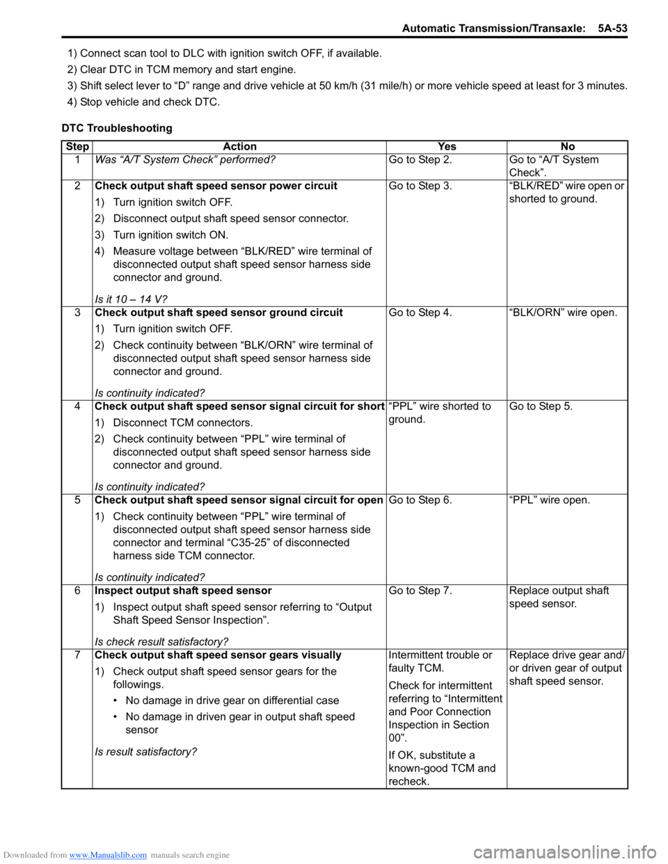
DTC Troubleshooting Step Action Yes No 1 Was “A/T System Check” performed? Go to Step 2. Go to “A/T System
Check”.
2 Check output shaft speed sensor power circuit
1) Turn ignition switch OFF.
2) Disconnect output shaft speed sensor connector.
3) Turn ignition switch ON.
4) Measure voltage between “BLK/RED” wire terminal of
disconnected output shaft speed sensor harness side
connector and ground.
Is it 10 – 14 V? Go to Step 3. “BLK/RED” wire open or
shorted to ground.
3 Check output shaft speed sensor ground circuit
1) Turn ignition switch OFF.
2) Check continuity between “BLK/ORN” wire terminal of
disconnected output shaft speed sensor harness side
connector and ground.
Is continuity indicated? Go to Step 4. “BLK/ORN” wire open.
4 Check output shaft speed sensor signal circuit for short
1) Disconnect TCM connectors.
2) Check continuity between “PPL” wire terminal of
disconnected output shaft speed sensor harness side
connector and ground.
Is continuity indicated? “PPL” wire shorted to
ground.
Go to Step 5.
5 Check output shaft speed sensor signal circuit for open
1) Check continuity between “PPL” wire terminal of
disconnected output shaft speed sensor harness side
connector and terminal “C35-25” of disconnected
harness side TCM connector.
Is continuity indicated? Go to Step 6. “PPL” wire open.
6 Inspect output shaft speed sensor
1) Inspect output shaft speed sensor referring to “Output
Shaft Speed Sensor Inspection”.
Is check result satisfactory? Go to Step 7. Replace output shaft
speed sensor.
7 Check output shaft speed sensor gears visually
1) Check output shaft speed sensor gears for the
followings.
• No damage in drive gear on differential case
• No damage in driven gear in output shaft speed sensor
Is result satisfactory? Intermittent trouble or
faulty TCM.
Check for intermittent
referring to “Intermittent
and Poor Connection
Inspection in Section
00”.
If OK, substitute a
known-good TCM and
recheck.Replace drive gear and/
or driven gear of output
shaft speed sensor.
Page 699 of 1496
Downloaded from www.Manualslib.com manuals search engine Automatic Transmission/Transaxle: 5A-55
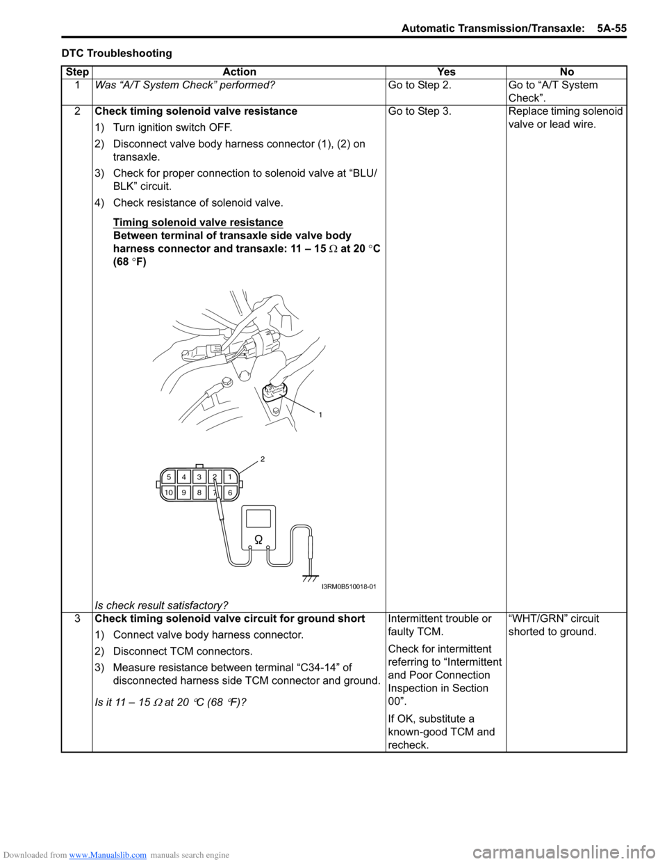
DTC TroubleshootingStep Action Yes No 1 Was “A/T System Check” performed? Go to Step 2. Go to “A/T System
Check”.
2 Check timing solenoid valve resistance
1) Turn ignition switch OFF.
2) Disconnect valve body harness connector (1), (2) on
transaxle.
3) Check for proper connection to solenoid valve at “BLU/ BLK” circuit.
4) Check resistance of solenoid valve.
Timing solenoid valve resistance
Between terminal of transaxle side valve body
harness connector and transaxle: 11 – 15 Ω at 20 °C
(68 °F)
Is check result satisfactory? Go to Step 3. Replace timing solenoid
valve or lead wire.
3 Check timing solenoid valve circuit for ground short
1) Connect valve body harness connector.
2) Disconnect TCM connectors.
3) Measure resistance between terminal “C34-14” of
disconnected harness side TCM connector and ground.
Is it 11 – 15
Ω at 20 °C (68 °F)? Intermittent trouble or
faulty TCM.
Check for intermittent
referring to “Intermittent
and Poor Connection
Inspection in Section
00”.
If OK, substitute a
known-good TCM and
recheck.“WHT/GRN” circuit
shorted to ground.
1
6
7
89
10 5
43 2
1
2
I3RM0B510018-01
Page 700 of 1496
Downloaded from www.Manualslib.com manuals search engine 5A-56 Automatic Transmission/Transaxle:
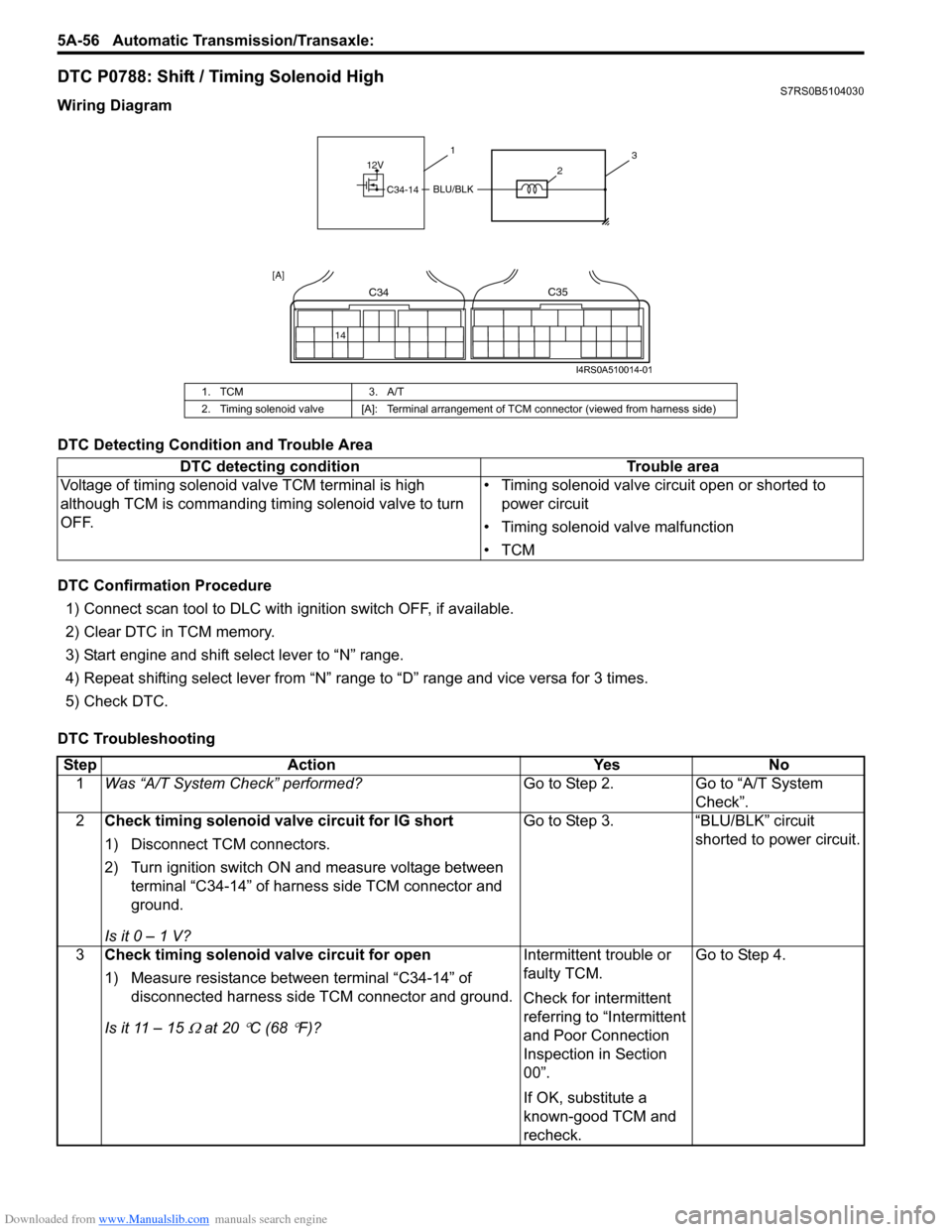
DTC P0788: Shift / Timing Solenoid HighS7RS0B5104030
Wiring Diagram
DTC Detecting Condition and Trouble Area
DTC Confirmation Procedure
1) Connect scan tool to DLC with ig nition switch OFF, if available.
2) Clear DTC in TCM memory.
3) Start engine and shift select lever to “N” range.
4) Repeat shifting select lever from “N” range to “D” range and vice versa for 3 times.
5) Check DTC.
DTC Troubleshooting
1. TCM 3. A/T
2. Timing solenoid valve [A]: Terminal arrangement of TCM connector (viewed from harness side)
DTC detecting condition Trouble area
Voltage of timing solenoid valve TCM terminal is high
although TCM is commanding timing solenoid valve to turn
OFF. • Timing solenoid valve circuit open or shorted to
power circuit
• Timing solenoid valve malfunction
•TCM
12V
C34-14BLU/BLK
31
2
14
C34C35
[A]
I4RS0A510014-01
Step Action YesNo
1 Was “A/T System Check” performed? Go to Step 2.Go to “A/T System
Check”.
2 Check timing solenoid valve circuit for IG short
1) Disconnect TCM connectors.
2) Turn ignition switch ON and measure voltage between
terminal “C34-14” of harness side TCM connector and
ground.
Is it 0 – 1 V? Go to Step 3.
“BLU/BLK” circuit
shorted to power circuit.
3 Check timing solenoid valve circuit for open
1) Measure resistance between terminal “C34-14” of
disconnected harness side TCM connector and ground.
Is it 11 – 15
Ω at 20 °C (68 °F)? Intermittent trouble or
faulty TCM.
Check for intermittent
referring to “Intermittent
and Poor Connection
Inspection in Section
00”.
If OK, substitute a
known-good TCM and
recheck.Go to Step 4.
Page 703 of 1496
Downloaded from www.Manualslib.com manuals search engine Automatic Transmission/Transaxle: 5A-59
DTC TroubleshootingStep Action Yes No 1 Was “A/T System Check” performed? Go to Step 2. Go to “A/T System
Check”.
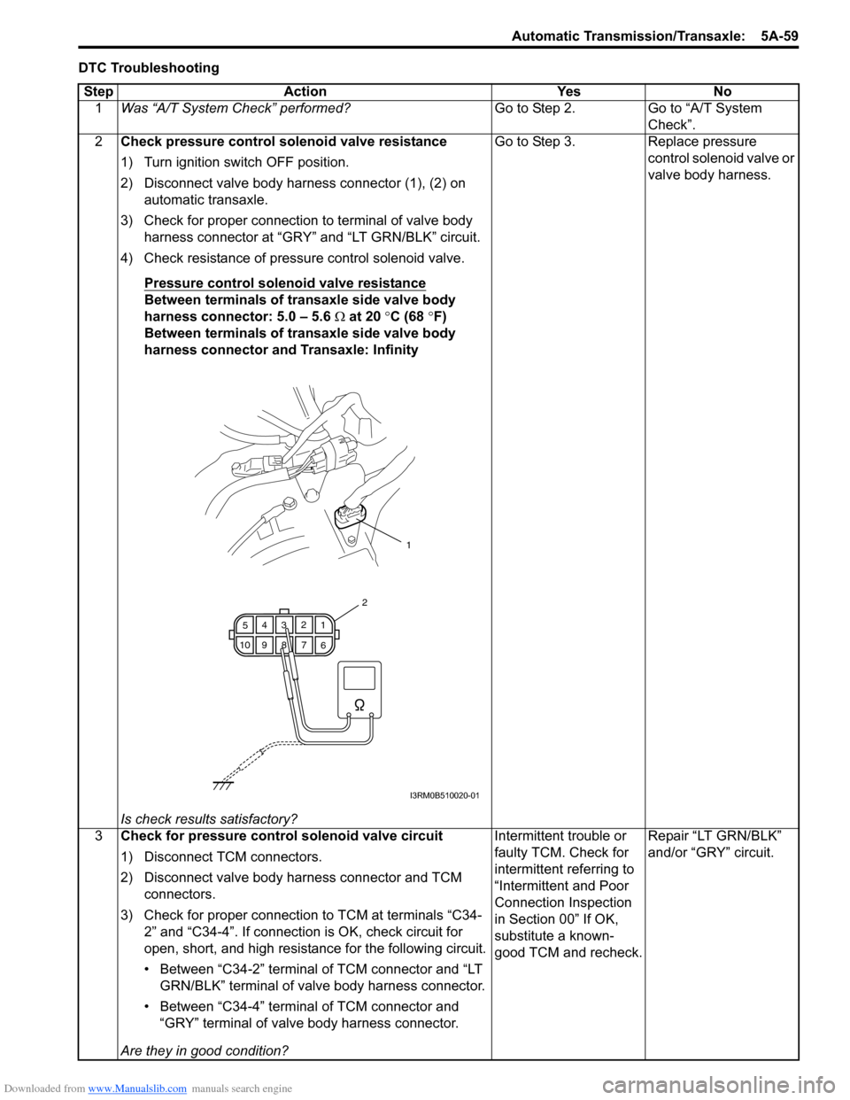
2 Check pressure control solenoid valve resistance
1) Turn ignition switch OFF position.
2) Disconnect valve body harness connector (1), (2) on
automatic transaxle.
3) Check for proper connection to terminal of valve body harness connector at “GRY” and “LT GRN/BLK” circuit.
4) Check resistance of pressure control solenoid valve.
Pressure control solenoid valve resistance
Between terminals of transaxle side valve body
harness connector: 5.0 – 5.6 Ω at 20 °C (68 °F)
Between terminals of transaxle side valve body
harness connector and Transaxle: Infinity
Is check results satisfactory? Go to Step 3. Replace pressure
control solenoid valve or
valve body harness.
3 Check for pressure control solenoid valve circuit
1) Disconnect TCM connectors.
2) Disconnect valve body harness connector and TCM
connectors.
3) Check for proper connection to TCM at terminals “C34- 2” and “C34-4”. If connection is OK, check circuit for
open, short, and high resistance for the following circuit.
• Between “C34-2” terminal of TCM connector and “LT GRN/BLK” terminal of valve body harness connector.
• Between “C34-4” terminal of TCM connector and “GRY” terminal of valve body harness connector.
Are they in good condition? Intermittent trouble or
faulty TCM. Check for
intermittent referring to
“Intermittent and Poor
Connection Inspection
in Section 00” If OK,
substitute a known-
good TCM and recheck.
Repair “LT GRN/BLK”
and/or “GRY” circuit.
1
6
7
89
10 5
43 2
1
2
I3RM0B510020-01