2005 SUZUKI SWIFT Can
[x] Cancel search: CanPage 227 of 1496
Downloaded from www.Manualslib.com manuals search engine Engine General Information and Diagnosis: 1A-177
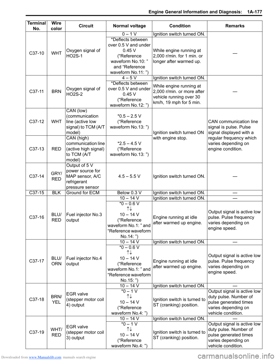
C37-10 WHTOxygen signal of
HO2S-1 0 – 1 V Ignition switch turned ON.
—
*Deflects between
over 0.5 V and under 0.45 V
(“Reference
waveform No.10: ” and “Reference
waveform No.11: ”) While engine running at
2,000 r/min. for 1 min. or
longer after warmed up.
C37-11 BRN Oxygen signal of
HO2S-2 4 – 5 V Ignition switch turned ON.
—
*Deflects between
over 0.5 V and under 0.45 V
(“Reference
waveform No.12: ”) While engine running at
2,000 r/min. or more after
vehicle running over 30
km/h, 19 mph for 5 min.
C37-12 WHT CAN (low)
(communication
line (active low
signal) to TCM (A/T
model) *0.5 – 2.5 V
(“Reference
waveform No.13: ”) Ignition switch turned ON
with engine stop. CAN communication line
signal is pulse. Pulse
signal displayed with a
regular frequency which
varies depending on
engine condition.
C37-13 RED CAN (high)
communication line
(active high signal)
to TCM (A/T
model) *2.5 – 4.5 V
(“Reference
waveform No.13: ”)
C37-14 GRY/
RED Output of 5 V
power source for
MAP sensor, A/C
refrigerant
pressure sensor
4.5 – 5.5 V Ignition switch turned ON. —
C37-15 BLK Ground for ECM Below 0.3 V Ignition switch turned ON. —
C37-16 BLU/
RED Fuel injector No.3
output 10 – 14 V Ignition switch turned ON. —
*0 – 0.6 V ↑↓
10 – 14 V
(“Reference
waveform No.1: ” and
“Reference waveform No.14: ”) Engine running at idle
after warmed up engine.
Output signal is active low
pulse. Pulse frequency
varies depending on
engine speed.
C37-17 BLU/
ORNFuel injector No.4
output 10 – 14 V Ignition switch turned ON. —
*0 – 0.6 V ↑↓
10 – 14 V
(“Reference
waveform No.1: ” and
“Reference waveform No.15: ”) Engine running at idle
after warmed up engine.
Output signal is active low
pulse. Pulse frequency
varies depending on
engine speed.
C37-18 BRN/
YEL EGR valve
(stepper motor coil
4) output 10 – 14 V Ignition switch turned ON. —
*0 – 1 V ↑↓
10 – 14 V
(“Reference
waveform No.4: ”) Ignition switch is turned to
ST (cranking) position. Output signal is active low
duty pulse. Number of
pulse generated times
varies depending on
vehicle condition.
C37-19 WHT/
RED EGR valve
(stepper motor coil
3) output 10 – 14 V Ignition switch turned ON. —
*0 – 1 V ↑↓
1
0 – 14 V
(“Reference
waveform No.4: ”) Ignition switch is turned to
ST (cranking) position. Output signal is active low
duty pulse. Number of
pulse generated times
varies depending on
vehicle condition.
Terminal
No. Wire
color Circuit Normal voltage
ConditionRemarks
Page 228 of 1496
Downloaded from www.Manualslib.com manuals search engine 1A-178 Engine General Information and Diagnosis:
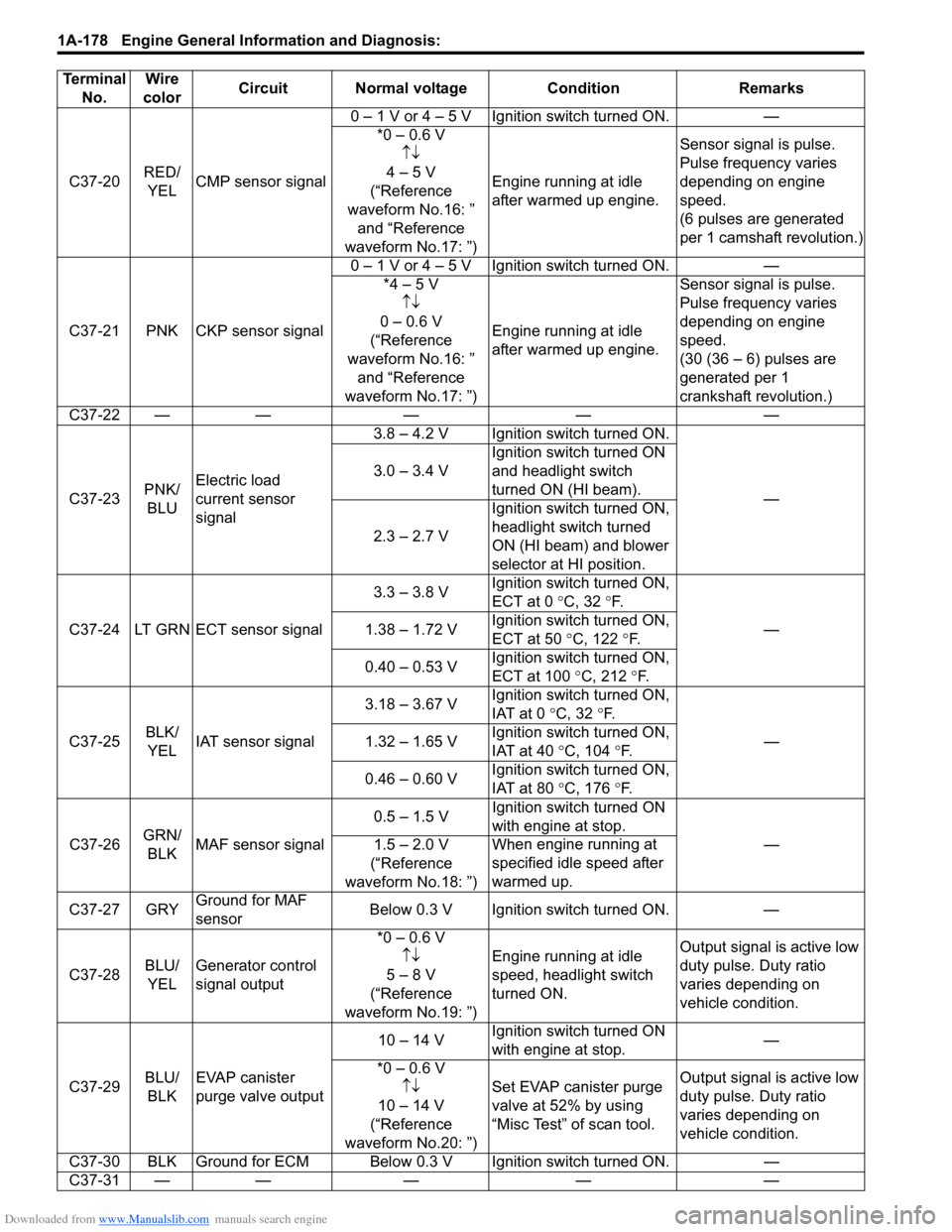
C37-20RED/
YEL CMP sensor signal 0 – 1 V or 4 – 5 V Ignition switch turned ON. —
*0 – 0.6 V↑↓
4 – 5 V
(“Reference
waveform No.16: ” and “Reference
waveform No.17: ”) Engine running at idle
after warmed up engine.
Sensor signal is pulse.
Pulse frequency varies
depending on engine
speed.
(6 pulses are generated
per 1 camshaft revolution.)
C37-21 PNK CKP sensor signal 0 – 1 V or 4 – 5 V Ignition switch turned ON. —
*4 – 5 V↑↓
0 – 0.6 V
(“Reference
waveform No.16: ” and “Reference
waveform No.17: ”) Engine running at idle
after warmed up engine. Sensor signal is pulse.
Pulse frequency varies
depending on engine
speed.
(30 (36 – 6) pulses are
generated per 1
crankshaft revolution.)
C37-22 — — — — —
C37-23 PNK/
BLU Electric load
current sensor
signal 3.8 – 4.2 V Ignition switch turned ON.
—
3.0 – 3.4 V
Ignition switch turned ON
and headlight switch
turned ON (HI beam).
2.3 – 2.7 V Ignition switch turned ON,
headlight switch turned
ON (HI beam) and blower
selector at HI position.
C37-24 LT GRN ECT sensor signal 3.3 – 3.8 V
Ignition switch turned ON,
ECT at 0
°C, 32 °F.
—
1.38 – 1.72 V Ignition switch turned ON,
ECT at 50
°C, 122 °F.
0.40 – 0.53 V Ignition switch turned ON,
ECT at 100
°C, 212 °F.
C37-25 BLK/
YEL IAT sensor signal 3.18 – 3.67 V
Ignition switch turned ON,
IAT at 0
°C, 32 °F.
—
1.32 – 1.65 V Ignition switch turned ON,
IAT at 40
°C, 104 °F.
0.46 – 0.60 V Ignition switch turned ON,
IAT at 80
°C, 176 °F.
C37-26 GRN/
BLK MAF sensor signal 0.5 – 1.5 V
Ignition switch turned ON
with engine at stop.
—
1.5 – 2.0 V
(“Reference
waveform No.18: ”) Wh
en engine running at
specified idle speed after
warmed up.
C37-27 GRY Ground for MAF
sensor Below 0.3 V Ignition switch turned ON.
—
C37-28 BLU/
YEL Generator control
signal output *0 – 0.6 V
↑↓
5 – 8 V
(“Reference
waveform No.19: ”) Engine running at idle
speed, headlight switch
turned ON.
Output signal is active low
duty pulse. Duty ratio
varies depending on
vehicle condition.
C37-29 BLU/
BLK EVAP canister
purge valve output 10 – 14 V
Ignition switch turned ON
with engine at stop. —
*0 – 0.6 V ↑↓
10 – 14 V
(“Reference
waveform No.20: ”) Set EVAP canister purge
valve at 52% by using
“Misc Test” of scan tool.
Output signal is active low
duty pulse. Duty ratio
varies depending on
vehicle condition.
C37-30 BLK Ground for ECM Below 0.3 V Ignition switch turned ON. —
C37-31 — —— — —
Terminal
No. Wire
color Circuit Normal voltage
ConditionRemarks
Page 230 of 1496
Downloaded from www.Manualslib.com manuals search engine 1A-180 Engine General Information and Diagnosis:
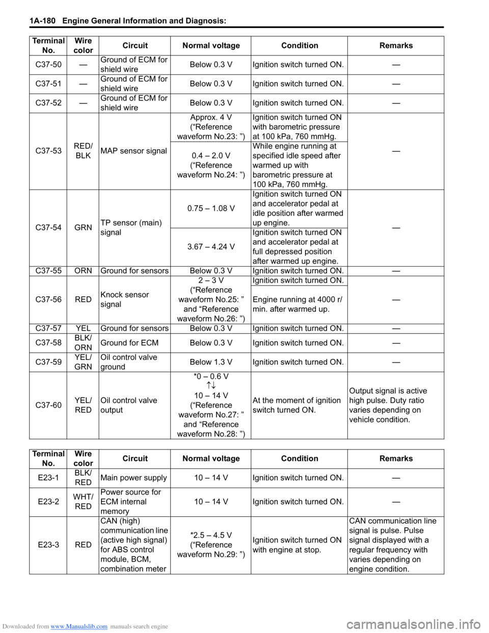
C37-50 —Ground of ECM for
shield wire Below 0.3 V Ignition switch turned ON. —
C37-51 — Ground of ECM for
shield wire Below 0.3 V Ignition switch turned ON. —
C37-52 — Ground of ECM for
shield wire Below 0.3 V Ignition switch turned ON. —
C37-53 RED/
BLK MAP sensor signal Approx. 4 V
(“Reference
waveform No.23: ”) Ignition switch turned ON
with barometric pressure
at 100 kPa, 760 mmHg.
—
0.4 – 2.0 V
(“Reference
waveform No.24: ”) While engine running at
specified idle speed after
warmed up with
barometric pressure at
100 kPa, 760 mmHg.
C37-54 GRN TP sensor (main)
signal 0.75 – 1.08 V
Ignition switch turned ON
and accelerator pedal at
idle position after warmed
up engine.
—
3.67 – 4.24 V Ignition switch turned ON
and accelerator pedal at
full depressed position
after warmed up engine.
C37-55 ORN Ground for sensors Below 0.3 V Ignition switch turned ON. —
C37-56 RED Knock sensor
signal 2 – 3 V
(“Reference
waveform No.25: ” and “Reference
waveform No.26: ”) Ignition switch turned ON.
—
Engine running at 4000 r/
min. after warmed up.
C37-57 YEL Ground for sensors Below 0.3 V Ignition switch turned ON. —
C37-58 BLK/
ORN Ground for ECM Below 0.3 V Ignition switch turned ON.
—
C37-59 YEL/
GRN Oil control valve
ground
Below 1.3 V Ignition switch turned ON.
—
C37-60 YEL/
RED Oil control valve
output *0 – 0.6 V
↑↓
10 – 14 V
(“Reference
waveform No.27: ” and “Reference
waveform No.28: ”) At the moment of ignition
switch turned ON.
Output signal is active
high pulse. Duty ratio
varies depending on
vehicle condition.
Terminal
No. Wire
color Circuit Normal voltage
ConditionRemarks
Terminal
No. Wire
color Circuit Normal voltage Condition Remarks
E23-1 BLK/
RED Main power supply 10 – 14 V Ignition switch turned ON. —
E23-2 WHT/
RED Power source for
ECM internal
memory
10 – 14 V Ignition switch turned ON. —
E23-3 RED CAN (high)
communication line
(active high signal)
for ABS control
module, BCM,
combination meter *2.5 – 4.5 V
(“Reference
waveform No.29: ”) Ignition switch turned ON
with engine at stop. CAN communication line
signal is pulse. Pulse
signal displayed with a
regular frequency with
varies depending on
engine condition.
Page 231 of 1496
Downloaded from www.Manualslib.com manuals search engine Engine General Information and Diagnosis: 1A-181
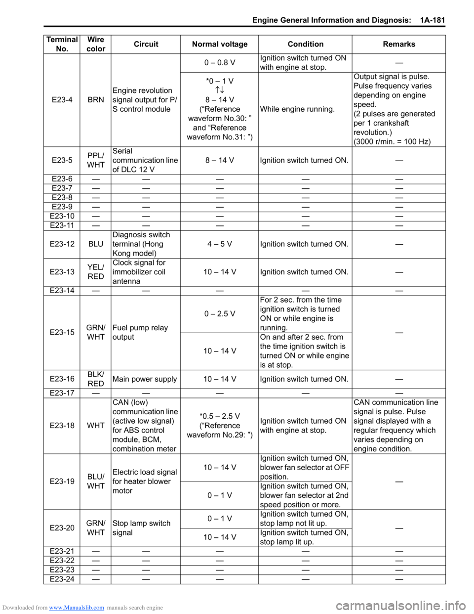
E23-4 BRNEngine revolution
signal output for P/
S control module 0 – 0.8 V
Ignition switch turned ON
with engine at stop. —
*0 – 1 V ↑↓
8 – 14 V
(“Reference
waveform No.30: ” and “Reference
waveform No.31: ”) While engine running. Output signal is pulse.
Pulse frequency varies
depending on engine
speed.
(2 pulses are generated
per 1 crankshaft
revolution.)
(3000 r/min. = 100 Hz)
E23-5 PPL/
WHT Serial
communication line
of DLC 12 V
8 – 14 V Ignition switch turned ON. —
E23-6 — — — — —
E23-7 — — — — —
E23-8 — — — — —
E23-9 — — — — —
E23-10 — — — — — E23-11 — — — — —
E23-12 BLU Diagnosis switch
terminal (Hong
Kong model) 4 – 5 V Ignition switch turned ON. —
E23-13 YEL/
RED Clock signal for
immobilizer coil
antenna
10 – 14 V Ignition switch turned ON. —
E23-14 — — — — —
E23-15 GRN/
WHT Fuel pump relay
output 0 – 2.5 V
For 2 sec. from the time
ignition switch is turned
ON or while engine is
running.
—
10 – 14 V On and after 2 sec. from
the time ignition switch is
turned ON or while engine
is at stop.
E23-16 BLK/
RED Main power supply 10 – 14 V Ignition switch turned ON. —
E23-17 — — — — —
E23-18 WHT CAN (low)
communication line
(active low signal)
for ABS control
module, BCM,
combination meter *0.5 – 2.5 V
(“Reference
waveform No.29: ”) Ignition switch turned ON
with engine at stop. CAN communication line
signal is pulse. Pulse
signal displayed with a
regular frequency which
varies depending on
engine condition.
E23-19 BLU/
WHT Electric load signal
for heater blower
motor 10 – 14 V
Ignition switch turned ON,
blower fan selector at OFF
position.
—
0 – 1 V Ignition switch turned ON,
blower fan selector at 2nd
speed position or more.
E23-20 GRN/
WHT Stop lamp switch
signal 0 – 1 V
Ignition switch turned ON,
stop lamp not lit up.
—
10 – 14 V Ignition switch turned ON,
stop lamp lit up.
E23-21 — — — — —
E23-22 — — — — —
E23-23 — — — — —
E23-24 — — — — —
Terminal
No. Wire
color Circuit Normal voltage Condition Remarks
Page 237 of 1496
Downloaded from www.Manualslib.com manuals search engine Engine General Information and Diagnosis: 1A-187
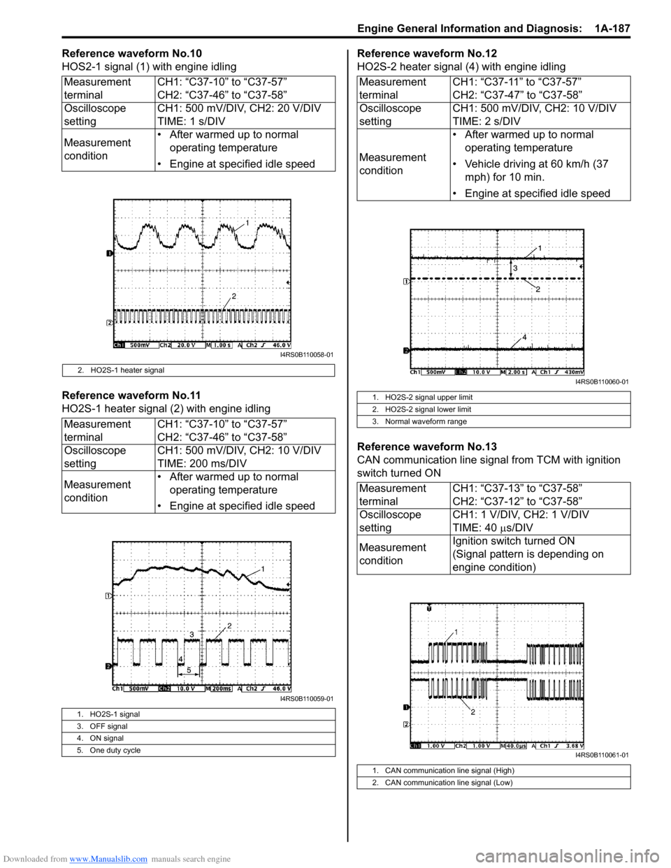
Reference waveform No.10
HOS2-1 signal (1) with engine idling
Reference waveform No.11
HO2S-1 heater signal (2) with engine idlingReference waveform No.12
HO2S-2 heater signal (4) with engine idling
Reference waveform No.13
CAN communication line signal from TCM with ignition
switch turned ON
Measurement
terminal
CH1: “C37-10” to “C37-57”
CH2: “C37-46” to “C37-58”
Oscilloscope
setting CH1: 500 mV/DIV, CH2: 20 V/DIV
TIME: 1 s/DIV
Measurement
condition • After warmed up to normal
operating temperature
• Engine at specified idle speed
2. HO2S-1 heater signal
Measurement
terminal CH1: “C37-10” to “C37-57”
CH2: “C37-46” to “C37-58”
Oscilloscope
setting CH1: 500 mV/DIV, CH2: 10 V/DIV
TIME: 200 ms/DIV
Measurement
condition • After warmed up to normal
operating temperature
• Engine at specified idle speed
1. HO2S-1 signal
3. OFF signal
4. ON signal
5. One duty cycle
I4RS0B110058-01
I4RS0B110059-01
Measurement
terminal CH1: “C37-11” to “C37-57”
CH2: “C37-47” to “C37-58”
Oscilloscope
setting CH1: 500 mV/DIV, CH2: 10 V/DIV
TIME: 2 s/DIV
Measurement
condition • After warmed up to normal
operating temperature
• Vehicle driving at 60 km/h (37 mph) for 10 min.
• Engine at specified idle speed
1. HO2S-2 signal upper limit
2. HO2S-2 signal lower limit
3. Normal waveform range
Measurement
terminal CH1: “C37-13” to “C37-58”
CH2: “C37-12” to “C37-58”
Oscilloscope
setting CH1: 1 V/DIV, CH2: 1 V/DIV
TIME: 40
µs/DIV
Measurement
condition Ignition switch turned ON
(Signal pattern is depending on
engine condition)
1. CAN communication line signal (High)
2. CAN communication line signal (Low)
I4RS0B110060-01
I4RS0B110061-01
Page 239 of 1496
Downloaded from www.Manualslib.com manuals search engine Engine General Information and Diagnosis: 1A-189
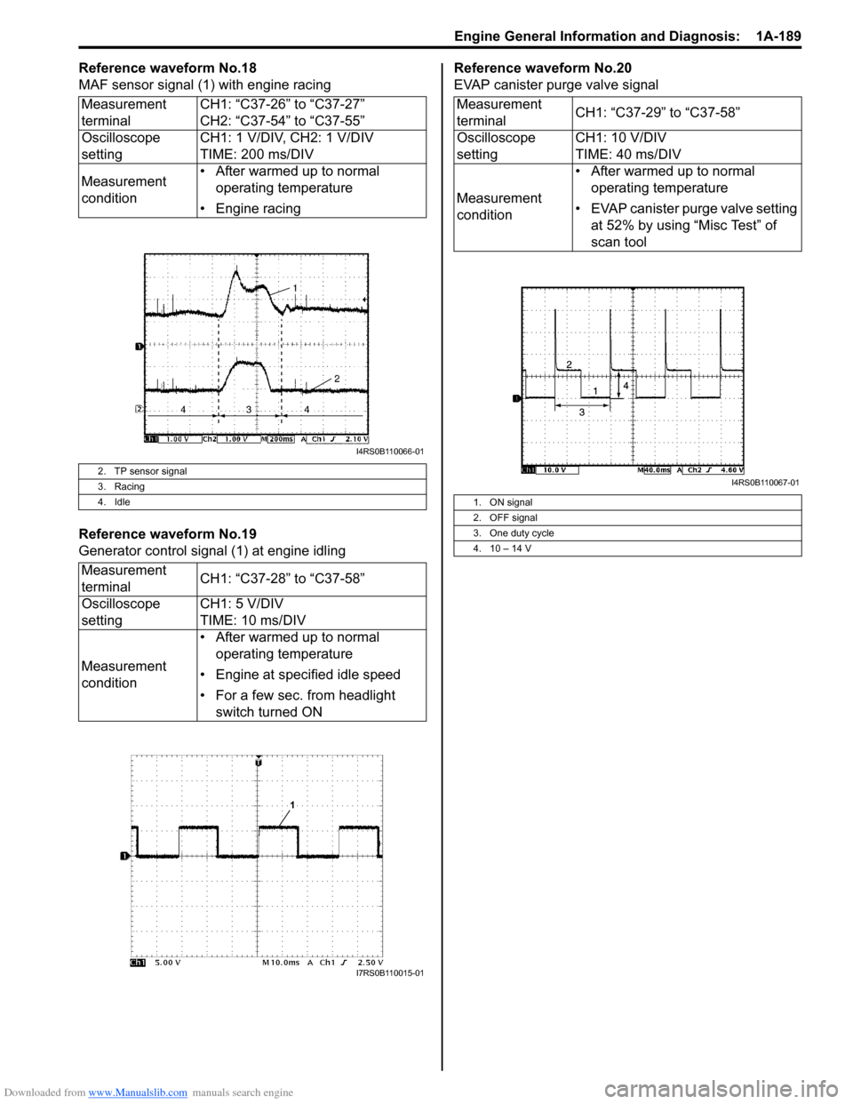
Reference waveform No.18
MAF sensor signal (1) with engine racing
Reference waveform No.19
Generator control signal (1) at engine idlingReference waveform No.20
EVAP canister purge valve signal
Measurement
terminal CH1: “C37-26” to “C37-27”
CH2: “C37-54” to “C37-55”
Oscilloscope
setting CH1: 1 V/DIV, CH2: 1 V/DIV
TIME: 200 ms/DIV
Measurement
condition • After warmed up to normal
operating temperature
• Engine racing
2. TP sensor signal
3. Racing
4. Idle
Measurement
terminal CH1: “C37-28” to “C37-58”
Oscilloscope
setting CH1: 5 V/DIV
TIME: 10 ms/DIV
Measurement
condition • After warmed up to normal
operating temperature
• Engine at specified idle speed
• For a few sec. from headlight switch turned ON
I4RS0B110066-01
I7RS0B110015-01
Measurement
terminal CH1: “C37-29” to “C37-58”
Oscilloscope
setting CH1: 10 V/DIV
TIME: 40 ms/DIV
Measurement
condition • After warmed up to normal
operating temperature
• EVAP canister purge valve setting at 52% by using “Misc Test” of
scan tool
1. ON signal
2. OFF signal
3. One duty cycle
4. 10 – 14 V
I4RS0B110067-01
Page 242 of 1496
Downloaded from www.Manualslib.com manuals search engine 1A-192 Engine General Information and Diagnosis:
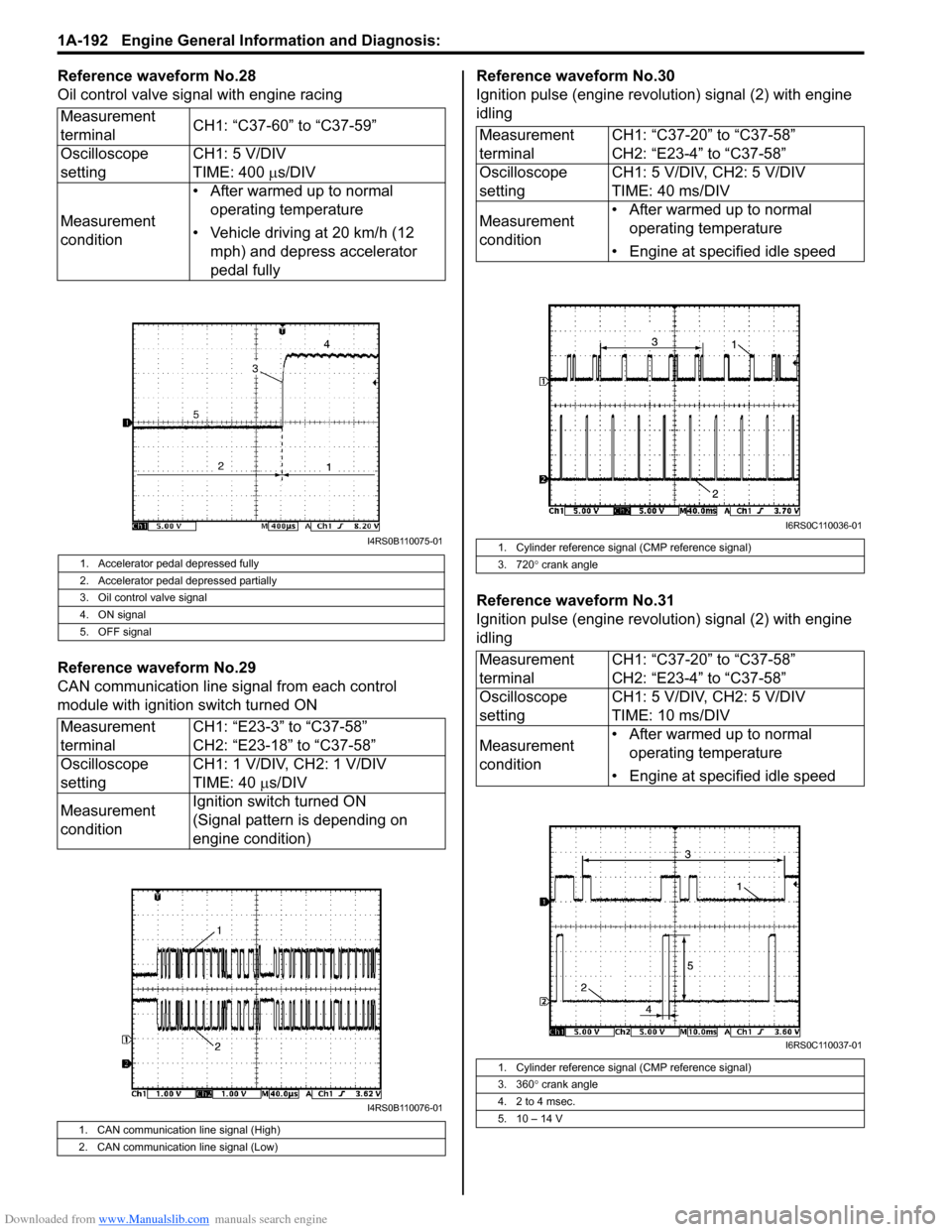
Reference waveform No.28
Oil control valve signal with engine racing
Reference waveform No.29
CAN communication line signal from each control
module with ignition switch turned ONReference waveform No.30
Ignition pulse (engine revolution) signal (2) with engine
idling
Reference waveform No.31
Ignition pulse (engine revolution) signal (2) with engine
idling
Measurement
terminal
CH1: “C37-60” to “C37-59”
Oscilloscope
setting CH1: 5 V/DIV
TIME: 400
µs/DIV
Measurement
condition • After warmed up to normal
operating temperature
• Vehicle driving at 20 km/h (12 mph) and depress accelerator
pedal fully
1. Accelerator pedal depressed fully
2. Accelerator pedal depressed partially
3. Oil control valve signal
4. ON signal
5. OFF signal
Measurement
terminal CH1: “E23-3” to “C37-58”
CH2: “E23-18” to “C37-58”
Oscilloscope
setting CH1: 1 V/DIV, CH2: 1 V/DIV
TIME: 40
µs/DIV
Measurement
condition Ignition switch turned ON
(Signal pattern is depending on
engine condition)
1. CAN communication line signal (High)
2. CAN communication line signal (Low)
I4RS0B110075-01
I4RS0B110076-01
Measurement
terminal
CH1: “C37-20” to “C37-58”
CH2: “E23-4” to “C37-58”
Oscilloscope
setting CH1: 5 V/DIV, CH2: 5 V/DIV
TIME: 40 ms/DIV
Measurement
condition • After warmed up to normal
operating temperature
• Engine at specified idle speed
1. Cylinder reference signal (CMP reference signal)
3. 720 ° crank angle
Measurement
terminal CH1: “C37-20” to “C37-58”
CH2: “E23-4” to “C37-58”
Oscilloscope
setting CH1: 5 V/DIV, CH2: 5 V/DIV
TIME: 10 ms/DIV
Measurement
condition • After warmed up to normal
operating temperature
• Engine at specified idle speed
1. Cylinder reference signal (CMP reference signal)
3. 360 ° crank angle
4. 2 to 4 msec.
5. 10 – 14 V
I6RS0C110036-01
I6RS0C110037-01
Page 243 of 1496
Downloaded from www.Manualslib.com manuals search engine Engine General Information and Diagnosis: 1A-193
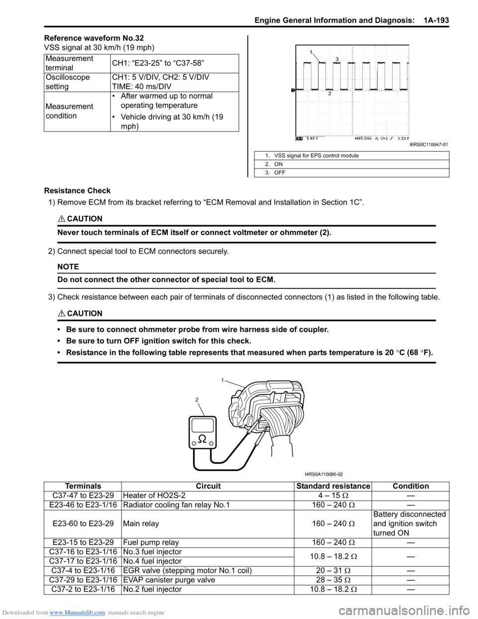
Reference waveform No.32
VSS signal at 30 km/h (19 mph)
Resistance Check1) Remove ECM from its bracket referring to “ECM Removal and Installation in Section 1C”.
CAUTION!
Never touch terminals of ECM itself or connect voltmeter or ohmmeter (2).
2) Connect special tool to ECM connectors securely.
NOTE
Do not connect the other connector of special tool to ECM.
3) Check resistance between each pair of terminals of disconnected connectors (1) as listed in the following table.
CAUTION!
• Be sure to connect ohmmeter probe from wire harness side of coupler.
• Be sure to turn OFF ignition switch for this check.
• Resistance in the following table represents that measured when parts temperature is 20 °C (68 °F).
Measurement
terminal CH1: “E23-25” to “C37-58”
Oscilloscope
setting CH1: 5 V/DIV, CH2: 5 V/DIV
TIME: 40 ms/DIV
Measurement
condition • After warmed up to normal
operating temperature
• Vehicle driving at 30 km/h (19 mph)
1. VSS signal for EPS control module
2. ON
3. OFF
I6RS0C110047-01
1
2
I4RS0A110086-02
Terminals CircuitStandard resistance Condition
C37-47 to E23-29 Heater of HO2S-2 4 – 15 Ω—
E23-46 to E23-1/16 Radiator cooling fan relay No.1 160 – 240 Ω —
E23-60 to E23-29 Main relay 160 – 240 ΩBattery disconnected
and ignition switch
turned ON
E23-15 to E23-29 Fuel pump relay 160 – 240 Ω —
C37-16 to E23-1/16 No.3 fuel injector 10.8 – 18.2 Ω —
C37-17 to E23-1/16 No.4 fuel injector
C37-4 to E23-1/16 EGR valve (st epping motor No.1 coil) 20 – 31 Ω —
C37-29 to E23-1/16 EVAP canister purge valve 28 – 35 Ω —
C37-2 to E23-1/16 No.2 fuel injector 10.8 – 18.2 Ω—