2005 SUZUKI SWIFT acc
[x] Cancel search: accPage 382 of 1496

Downloaded from www.Manualslib.com manuals search engine 1G-7 Fuel System:
Fuel Pressure Relief ProcedureS7RS0B1706003
CAUTION!
This work must not be done when engine is
hot. If done so, it may cause adverse effect to
catalyst.
NOTE
If ECM detects DTC(s) after servicing, clear
DTC(s) referring to “DTC Clearance in
Section 1A”.
1) Make sure that engine is cold.
2) Shift transaxle gear shift lever in “Neutral” (shift select lever in “P” range for A/T model), set parking
brake and block drive wheels.
3) Remove relay / fuse box cover.
4) Disconnect fuel pump relay (1) from relay / fuse box (2).
5) Remove fuel filter cap in order to release fuel vapor pressure in fuel tank, and then reinstall it.
6) Start engine and run it until engine stops for lack of fuel. Repeat cranking engine 2 – 3 times for about 3
seconds each time in order to dissipate fuel pressure
in lines. Fuel connections are now safe for servicing.
7) After servicing, connect fuel pump relay (1) to relay / fuse box and install re lay / fuse box cover.
Fuel Leakage Check ProcedureS7RS0B1706004
After performing any service on fuel system, check to
make sure that there are no fuel leakages as follows.
1) Turn ON ignition switch for 3 seconds (to operate fuel pump) and then turn it OFF.
Repeat this (ON and OFF) 3 or 4 times and apply
fuel pressure to fuel line until fuel pressure is felt by
hand placed on fuel feed hose.
2) In this state, check to see that there are no fuel leakages from any part of fuel system.
Fuel Lines On-Vehicle InspectionS7RS0B1706005
CAUTION!
Due to the fact that fuel feed line (1) is under
high pressure, use special care when
servicing it.
Visually inspect fuel lines for evidence of fuel leakage,
hose crack and deterioration or damage.
Make sure all cl amps are secure.
Replace parts as needed.
Fuel Pipe Removal and InstallationS7RS0B1706006
WARNING!
Before starting the following procedure, be
sure to observe “Precautions on Fuel System
Service” in order to reduce the risk or fire
and personal injury.
Removal
1) Relieve fuel pressure in fuel feed line according to “Fuel Pressure Relief Procedure”.
2) Disconnect negative cable at battery.
3) Disconnect fuel pipe joint and fuel hose (3) from fuel pipe (2) at the front and rear of each fuel pipe
referring to “Fuel Hose Disconnecting and
Reconnecting”.
4) Mark the location of clamps (1) on fuel pipes (2), so that the clamps can be reinstalled to where they
were.
5) Remove pipes (2) with clamp (1) from vehicle.
6) Remove clamp (1) from pipes (2).
1
I4RS0A170004-01
1
I4RS0A170005-01
2
13
I4RS0A170020-01
Page 383 of 1496

Downloaded from www.Manualslib.com manuals search engine Fuel System: 1G-8
Installation1) Install clamps to marked location on pipes. If clamp is deformed, its claw is bent or broken, replace it with
new one.
2) Install pipes with pipe clamps to vehicle.
3) Connect fuel hoses and pipes to each pipe referring to “Fuel Hose Disconnecting and Reconnecting”.
4) Connect negative cable at battery.
5) With engine OFF, turn igniti on switch to ON position
and check for fuel leaks.
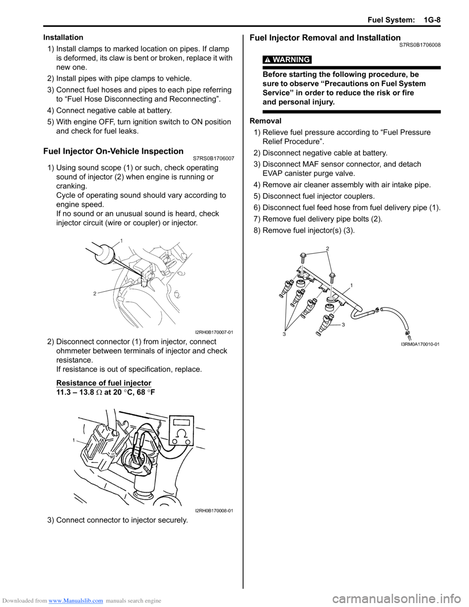
Fuel Injector On-Vehicle InspectionS7RS0B1706007
1) Using sound scope (1) or such, check operating sound of injector (2) when engine is running or
cranking.
Cycle of operating sound should vary according to
engine speed.
If no sound or an unusual sound is heard, check
injector circuit (wire or coupler) or injector.
2) Disconnect connector (1) from injector, connect ohmmeter between terminals of injector and check
resistance.
If resistance is out of specification, replace.
Resistance of fuel injector
11.3 – 13.8 Ω at 20 °C, 68 °F
3) Connect connector to injector securely.
Fuel Injector Removal and InstallationS7RS0B1706008
WARNING!
Before starting the following procedure, be
sure to observe “Precautions on Fuel System
Service” in order to reduce the risk or fire
and personal injury.
Removal 1) Relieve fuel pressure according to “Fuel Pressure Relief Procedure”.
2) Disconnect negative cable at battery.
3) Disconnect MAF sensor connector, and detach EVAP canister purge valve.
4) Remove air cleaner assembly with air intake pipe.
5) Disconnect fuel injector couplers.
6) Disconnect fuel feed hose from fuel delivery pipe (1).
7) Remove fuel delivery pipe bolts (2).
8) Remove fuel injector(s) (3).
I2RH0B170007-01
I2RH0B170008-01
2
1
3
3
I3RM0A170010-01
Page 384 of 1496

Downloaded from www.Manualslib.com manuals search engine 1G-9 Fuel System:
Installation
Reverse removal procedure for installation noting the
following.
• Replace injector O-ring (1) with new one using care not to damage it.
• Check if cushion (2) is scor ed or damaged. If it is,
replace with new one.
• Apply thin coat of fuel to O-rings (1) and then install injectors (3) into delivery pipe (4) and cylinder head.
Make sure that injectors rota te smoothly (6). If not,
probable cause is incorrect installation of O-ring.
Replace O-ring with new one.
• Tighten delivery pipe bolts (5) to specified torque and make sure that inject ors rotate smoothly.
Tightening torque
Fuel delivery pipe bolt (a): 25 N·m (2.5 kgf-m, 18.0
lb-ft)
• After installation, with engine OFF and ignition switch ON, check for fuel leaks around fuel line connection.Fuel Injector InspectionS7RS0B1706009
WARNING!
Before starting the following procedure, be
sure to observe “Precautions on Fuel System
Service” in order to reduce the risk or fire
and personal injury.
1) Relieve fuel pressure according to “Fuel Pressure Relief Procedure” if equipped.
2) Disconnect fuel feed hose from delivery pipe.
3) Set special tools as follows.
Special tool
(A): 09912–58421
(B): 09930–88530
(C): 09912–57610
a) Fit washer (1) (inside diameter 13.5 – 14.5 mm (0.532 – 0.570 in.)) to injector (2), and then
install injector to special tool (A).
b) Connect special tool (B) to injector.
c) Install special tool (C) to special tool (A).
d) Connect fuel feed hose to special tool (A).
I3RM0A170011-01
(B)
(A)
(A) (C)
2
1
I6RW0B170014-01
Page 387 of 1496

Downloaded from www.Manualslib.com manuals search engine Fuel System: 1G-12
Fuel Tank Inlet Valve InspectionS7RS0B1706012
WARNING!
Before starting the following procedure, be
sure to observe “Precautions on Fuel System
Service” in order to reduce the risk or fire
and personal injury.
Check fuel tank inlet valve for the following.
If any damage or malfunction is found, replace.
•Damage
• Smooth opening and closing
Fuel Tank Removal and InstallationS7RS0B1706013
WARNING!
Before starting the following procedure, be
sure to observe “Precautions on Fuel System
Service” in order to reduce the risk or fire
and personal injury.
Removal1) Relieve fuel pressure in fuel feed line according to
“Fuel Pressure Relief Procedure”.
2) Disconnect negative cable at battery.
3) Hoist vehicle.
4) Remove exhaust center pipe.
5) Disconnect fuel filler hose and breather hose from
filler neck referring to “Fue l Tank Inlet Valve Removal
and Installation”.
6) Due to absence of fuel tank drain plug, drain fuel tank by pumping fuel out through fuel tank filler.
Use hand operated pump device to drain fuel tank.
CAUTION!
• Do not force pump hose into fuel tank, or pump hose may damage fuel tank inlet
valve.
• Never store fuel in an open container due to possibility of fire or explosion.
7) Disconnect fuel pipe joint and fuel hoses (1) from fuel pipes (2) referring to “Fuel Hose Disconnecting
and Reconnecting”.
8) Support fuel tank (1) with jack (2) and remove its mounting bolts.
9) Lower fuel tank a little as to disconnect wire harness at connector (1) and ground wire (2), then remove
fuel tank.
I2RH0B170019-01
12
I4RS0A170008-01
12
I4RS0A170009-01
1
2
I6RS0C170005-02
Page 393 of 1496

Downloaded from www.Manualslib.com manuals search engine Ignition System: 1H-1
Engine
Ignition System
General Description
Ignition System ConstructionS7RS0B1801001
The ignition system is an electronic (distributorless) ignition system. It consists of the parts as described below.
• ECM
It detects the engine and vehicle conditions through the si gnals from the sensors, determines the most suitable
ignition timing and time for electricity to flow to the primar y coil and sends a signal to the ignitor (power unit) in the
ignition coil assembly.
• Ignition coil assembly (including an ignitor)
The ignition coil assembly has a built -in ignitor which turns ON and OFF the current flow to the primary coil
according to the signal from ECM. When the current flow to the primary coil is turned OFF, a high voltage is induced
in the secondary coil.
• High-tension cords and spark plugs
• CMP sensor (Camshaft position sensor) and CKP sensor (Crankshaft position sensor)
Using signals from these sensors, ECM identifies the specific cylinder whose piston is in the compression stroke,
detects the crank angle and adjusts in itial ignition timing automatically.
• TP sensor, ECT sensor, MAP sensor, MAF sensor, IAT sensor, knock sensor and other sensors / switches
Although this ignition system does not have a distributor, it has two ignition coil assemblies (one is for No.1 and No.4
spark plugs and the other is for No.2 and No.3 spark plugs). W hen an ignition signal is sent from ECM to the ignitor in
the ignition coil assembly for No.1 and No.4 spark plugs, a high voltage is induced in the secondary coil and that
passes through the high-tension cords and causes No.1 and No.4 spark plugs to spark simultaneously. Likewise,
when an ignition signal is sent to the ignitor in the ot her ignition coil assembly, No.2 and No.3 spark plugs spark
simultaneously.
Page 394 of 1496

Downloaded from www.Manualslib.com manuals search engine 1H-2 Ignition System:
Schematic and Routing Diagram
Ignition System Wiring Circuit DiagramS7RS0B1802001
E23-60
E23-29 12V 5V
5V
E23-1
E23-16
BLK/WHT
BLK/RED
BLK/RED BLK/RED
BLK/YELBLK/YEL
BLK/YEL
GRN
BLKWHT
WHT
BRN/WHT
BLK/ORN
BLK
BLK
C37-20
BLK/RED
PNK
5V
C37-21
BLK/WHT
7
3 4
1
12 5
6
2
11
8
9
10
GRN/YEL
GRN/WHT
C37-6
C37-5 5V
5V
RED/YEL
C37-58
C37-15
C37-30
E23
C37
34
1819
567
1011
17
20
47 46
495051
2122
52 16
25 9
24
14
29
55
57 54 53
59
60 58 2
262728
15
30
56 4832 31
34353637
40
42 39 38
44
45 43 41 331
1213
238
34
1819
567
1011
17
20
47 46
495051
2122
52 16
25 9
24
14
29
55
57 54 53
59
60 58 2
262728
15
30
56 4832 31
34353637
40
42 39 38
44
45 43 41 331
1213
238
13
14
15
16
17
50A50A80A
BLK/ORN
E23-31 BLK
I4RS0B180001-01
1. Ignition switch 7. No.1 spark plug 13. Individual circuit fuse box
No.1
2. Main relay 8. No.2 spark plug 14. “IG ACC” fuse
3. Ignition coil assembly for No.1 and No.4 spark plugs 9. No.3 spark plug 15. “FI” fuse
4. Ignition coil assembly for No.2 and No.3 spark plugs 10. No.4 spark plug 16. Junction block assembly
5. CMP sensor 11. Sensed information (MAP sensor, ECT sensor, MAF and IAT
sensor, TP sensor, Knock sensor, VSS, Electric load signal,
Engine start signal) 17. “IG COIL” fuse
6. CKP sensor 12. Battery fuse box
Page 411 of 1496

Downloaded from www.Manualslib.com manuals search engine Charging System: 1J-1
Engine
Charging System
General Description
Battery DescriptionS7RS0B1A01001
The battery has three major functions in the electrical
system.
• It is a source of electrical energy for cranking the engine.
• It acts as a voltage stabilizer for the electrical system.
• It can, for a limited time, provide energy when the electrical load exceeds the output of the generator.
Carrier and Hold-Down
The battery carrier should be in good condition so that it
will support the battery securely and keep it level. Before
installing the battery, the ba ttery carrier and hold-down
clamp should be clean and free from corrosion and
make certain there are no parts in carrier.
To prevent the battery from shaking in its carrier, the
hold-down bolts should be tight enough but not over-
tightened.
Electrolyte Freezing
The freezing point of electrolyte depends on its specific
gravity. Since freezing may ruin a battery, it should be
protected against freezing by keeping it in a fully
charged condition. If a battery is frozen accidentally, it
should not be charged until it is warmed.
Sulfation
If the battery is allowed to stand for a long period in
discharged condition, the lead sulfate becomes
converted into a hard, cryst alline substance, which will
not easily turn back to the active material again during
the subsequent recharging. “Sulfation” means the result
as well as the process of that reaction. Such a battery
can be revived by very slow charging and may be
restored to usable condition but its capacity is lower than
before. Built-In Indicator (If Equipped)
The battery has a built-in temperature compensated
indicator in the top of the battery. This indicator is to be
used with the following diagnostic procedure. When
checking the indicator, make sure that the battery has a
clean top. A light may be needed in some poorly-lit
areas.
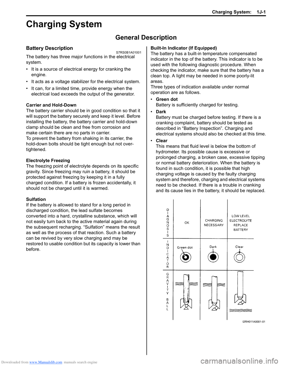
Three types of indication available under normal
operation are as follows.
•
Green dot
Battery is sufficiently charged for testing.
• Dark
Battery must be charged before testing. If there is a
cranking complaint, battery should be tested as
described in “Battery Inspection”. Charging and
electrical systems should also be checked at this time.
• Clear
This means that fluid level is below the bottom of
hydrometer. Its possible cause is excessive or
prolonged charging, a broken case, excessive tipping
or normal battery deteriorat ion. When the battery is
found in such condition, it is possible that high
charging voltage is caused by the faulty charging
system and therefore, charging and electrical systems
need to be checked. If there is a trouble in cranking
and its cause lies in the battery, it should be replaced.
I2RH011A0001-01
Page 414 of 1496

Downloaded from www.Manualslib.com manuals search engine 1J-4 Charging System:
Diagnostic Information and Procedures
Battery InspectionS7RS0B1A04001
Common Causes of Failure
A battery is not designed to last indefinitely; however, with proper care, it will provide many years of service. If the
battery performs satisfactorily during te st but fails to operate properly for no apparent reason, the following are some
factors that may point to the cause of trouble:
• Accessories left on overnight or for an extended period without the generator operating.
• Slow average driving speeds for short periods.
• Electrical load exceeding generator output partic ularly with addition of aftermarket equipment.
• Defects in charging system such as high resistance, s lipping drive belt, loose generator output terminal, faulty
generator or voltage regulator, Refer to “Generator Symptom Diagnosis”.
• Battery abuse, including failure to keep battery cable terminals clean and tight or loose battery hold down.
• Mechanical problems in electrical sys tem such as shorted or pinched wires.
Visual Inspection
Check for obvious damage, such as cracked or broken case or cover, that could permit loss of electrolyte. If obvious
damage is noted, replace battery. Determine cause of damage and correct as needed.
Generator Symptom DiagnosisS7RS0B1A04002
CAUTION!
• Do not mistake polarities of “IG” terminal and “L” terminal.
• Do not create short circuit between “IG” and “L” terminals. Always connect these terminals through a lamp.
• Do not connect any load between “L” and “E” terminals.
• When connecting charger or booster battery to vehicle battery, refer to “Jump Starting in Case of Emergency”.
Trouble in charging system will show up as one or more of the following conditions:
1) Faulty indicator lamp operation.
2) An undercharged battery as evidenced by slow cranking or indicator dark.
3) An overcharged battery as evidenced by ex cessive spewing of electrolyte from vents.
Condition Possible cause Correction / Reference Item
Noisy generator Loose drive belt Adjust or replace drive belt.
Loose drive belt pulley Tighten by specified torque.
Loose mounting bolts Tighten by specified torque.
Worn or dirty bearings Replace.
Defective diode or stator Replace.
Charge light does not
light with ignition ON and
engine off Fuse blown
Replace fuse and check for shorted circuit.
Indicator lamp (LED) faulty Replace combination meter.
Wiring connection loose Tighten loose connection.
IC regulator or field coil faulty Replace.
Poor contact between brush and slip
ring Repair or replace.
Charge light does not go
out with engine running
(battery requires frequent
recharging) Drive belt loose or worn
Adjust or replace drive belt.
IC regulator or generator faulty Replace.
Wiring faulty Repair wiring.