2005 SUZUKI SWIFT ESP
[x] Cancel search: ESPPage 675 of 1496
Downloaded from www.Manualslib.com manuals search engine Automatic Transmission/Transaxle: 5A-31
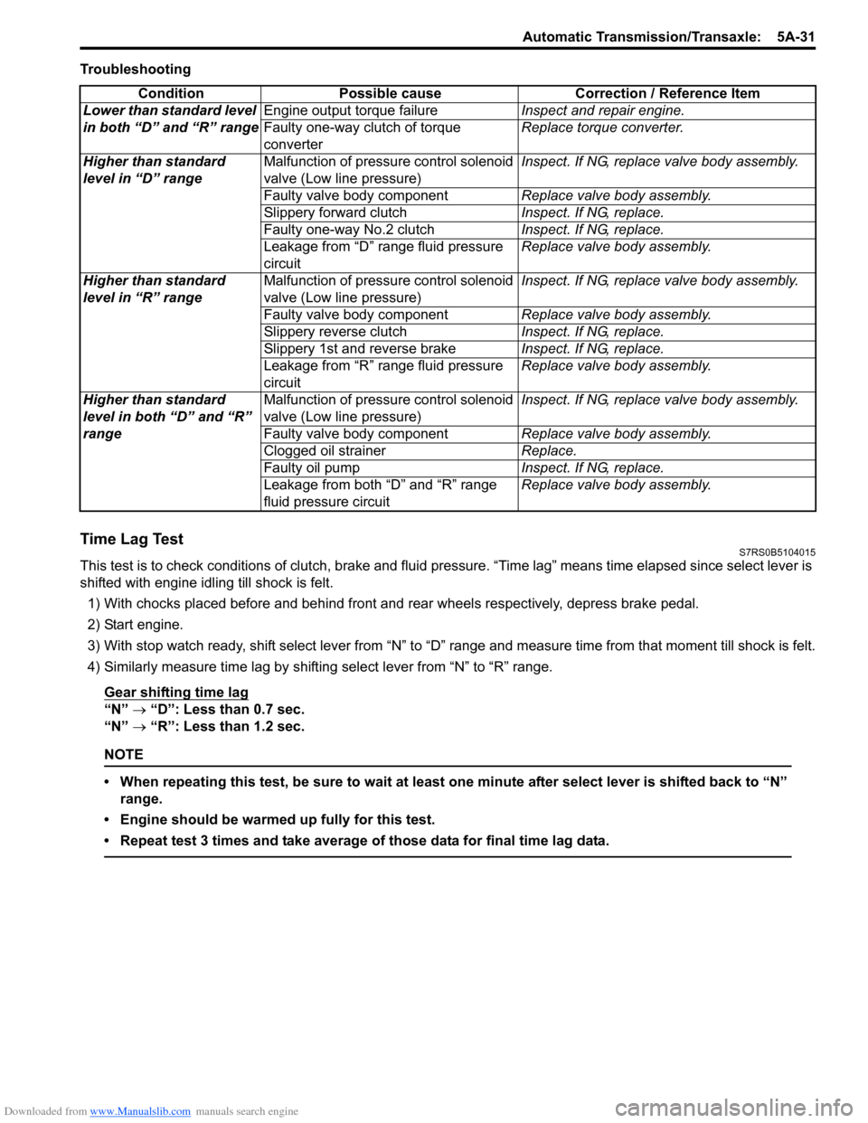
Troubleshooting
Time Lag TestS7RS0B5104015
This test is to check conditions of clutch, brake and fluid pressure. “Time lag” means time elapsed since select lever is
shifted with engine idling till shock is felt.
1) With chocks placed before and behind front and rear wheels respectively, depress brake pedal.
2) Start engine.
3) With stop watch ready, shift select lever from “N” to “D” range an d measure time from that moment till shock is felt.
4) Similarly measure time lag by shifting select lever from “N” to “R” range.
Gear shifting time lag
“N” → “D”: Less than 0.7 sec.
“N” → “R”: Less than 1.2 sec.
NOTE
• When repeating this test, be sure to wait at least one minute after select lever is shifted back to “N”
range.
• Engine should be warmed up fully for this test.
• Repeat test 3 times and take average of those data for final time lag data.
Condition Possible cause Correction / Reference Item
Lower than standard level
in both “D” and “R” range Engine output torque failure
Inspect and repair engine.
Faulty one-way clutch of torque
converter Replace torque converter.
Higher than standard
level in “D” range Malfunction of pressure control solenoid
valve (Low line pressure) Inspect. If NG, replace valve body assembly.
Faulty valve body component Replace valve body assembly.
Slippery forward clutch Inspect. If NG, replace.
Faulty one-way No.2 clutch Inspect. If NG, replace.
Leakage from “D” range fluid pressure
circuit Replace valve body assembly.
Higher than standard
level in “R” range Malfunction of pressure control solenoid
valve (Low line pressure) Inspect. If NG, replace valve body assembly.
Faulty valve body component Replace valve body assembly.
Slippery reverse clutch Inspect. If NG, replace.
Slippery 1st and reverse brake Inspect. If NG, replace.
Leakage from “R” range fluid pressure
circuit Replace valve body assembly.
Higher than standard
level in both “D” and “R”
range Malfunction of pressure control solenoid
valve (Low line pressure)
Inspect. If NG, replace valve body assembly.
Faulty valve body component Replace valve body assembly.
Clogged oil strainer Replace.
Faulty oil pump Inspect. If NG, replace.
Leakage from both “D” and “R” range
fluid pressure circuit Replace valve body assembly.
Page 689 of 1496
Downloaded from www.Manualslib.com manuals search engine Automatic Transmission/Transaxle: 5A-45
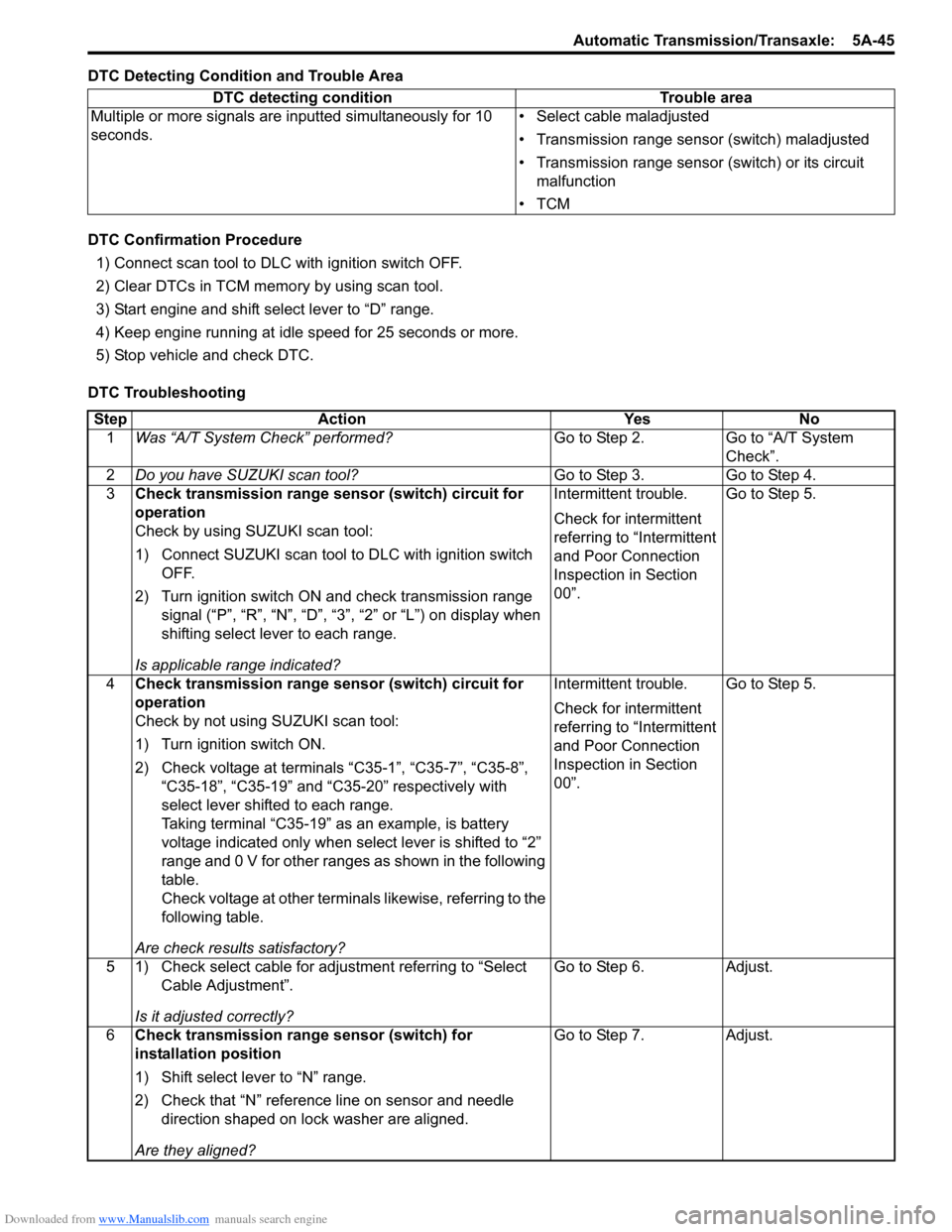
DTC Detecting Condition and Trouble Area
DTC Confirmation Procedure1) Connect scan tool to DLC with ignition switch OFF.
2) Clear DTCs in TCM memo ry by using scan tool.
3) Start engine and shift select lever to “D” range.
4) Keep engine running at idle speed for 25 seconds or more.
5) Stop vehicle and check DTC.
DTC Troubleshooting DTC detecting condition Trouble area
Multiple or more signals are inputted simultaneously for 10
seconds. • Select cable maladjusted
• Transmission range sensor (switch) maladjusted
• Transmission range sensor (switch) or its circuit
malfunction
•TCM
Step Action YesNo
1 Was “A/T System Check” performed? Go to Step 2.Go to “A/T System
Check”.
2 Do you have SUZUKI scan tool? Go to Step 3.Go to Step 4.
3 Check transmission range sensor (switch) circuit for
operation
Check by using SUZUKI scan tool:
1) Connect SUZUKI scan tool to DLC with ignition switch
OFF.
2) Turn ignition switch ON and check transmission range signal (“P”, “R”, “N”, “D”, “3”, “2” or “L”) on display when
shifting select lever to each range.
Is applicable range indicated? Intermittent trouble.
Check for intermittent
referring to “Intermittent
and Poor Connection
Inspection in Section
00”.
Go to Step 5.
4 Check transmission range sensor (switch) circuit for
operation
Check by not using SUZUKI scan tool:
1) Turn ignition switch ON.
2) Check voltage at terminals “C35-1”, “C35-7”, “C35-8”,
“C35-18”, “C35-19” and “C35-20” respectively with
select lever shifted to each range.
Taking terminal “C35-19” as an example, is battery
voltage indicated only when se lect lever is shifted to “2”
range and 0 V for other ranges as shown in the following
table.
Check voltage at other terminals likewise, referring to the
following table.
Are check results satisfactory? Intermittent trouble.
Check for intermittent
referring to “Intermittent
and Poor Connection
Inspection in Section
00”.
Go to Step 5.
5 1) Check select cable for adjustment referring to “Select Cable Adjustment”.
Is it adjusted correctly? Go to Step 6.
Adjust.
6 Check transmission range sensor (switch) for
installation position
1) Shift select lever to “N” range.
2) Check that “N” reference line on sensor and needle
direction shaped on lock washer are aligned.
Are they aligned? Go to Step 7.
Adjust.
Page 691 of 1496

Downloaded from www.Manualslib.com manuals search engine Automatic Transmission/Transaxle: 5A-47
DTC Confirmation Procedure
WARNING!
• When performing a road test, select a place where there is no traffic or possibility of a traffic accident and be very careful during testing to avoid occurrence of an accident.
• Road test should be carried out with 2 persons, a driver and a tester, on a level road.
1) Connect scan tool to DLC with ignition switch OFF.
2) Clear DTCs in TCM memo ry by using scan tool.
3) Start engine and shift select lever to “D” range.
4) Start vehicle and increase vehicle speed to 40 km/h (25 mile/h) or more for 1 minutes.
5) Stop vehicle and turn ignition switch OFF.
6) Repeat Step 3) to 4) one time.
7) Stop vehicle and check DTC.
DTC Troubleshooting Step Action YesNo
1 Was “A/T System Check” performed? Go to Step 2.Go to “A/T System
Check”.
2 Do you have SUZUKI scan tool? Go to Step 3.Go to Step 4.
3 Check transmission range sensor (switch) circuit for
operation
Check by using SUZUKI scan tool:
1) Connect SUZUKI scan tool to DLC with ignition switch
OFF.
2) Turn ignition switch ON and check transmission range signal (P, R, N, D, 3, 2 or L) on display when shifting
select lever to each range.
Is applicable range indicated? Intermittent trouble.
Check for intermittent
referring to “Intermittent
and Poor Connection
Inspection in Section
00”
Go to Step 5.
4 Check transmission range sensor (switch) circuit for
operation
Check by not using SUZUKI scan tool:
1) Turn ignition switch ON.
2) Check voltage at terminals “C35-1”, “C35-7”, “C35-8”,
“C35-18”, “C35-19” and “C35-20” respectively with
select lever shifted to each range.
Taking terminal “C35-19” as an example, is battery
voltage indicated only when se lect lever is shifted to “2”
range and 0 V for other ranges as shown in the following
table.
Check voltage at other terminals likewise, referring to the
following table.
Are check results satisfactory? Intermittent trouble.
Check for intermittent
referring to “Intermittent
and Poor Connection
Inspection in Section
00”.
Go to Step 5.
5 1) Check select cable for adjustment referring to “Select Cable Adjustment”.
Is it adjusted correctly? Go to Step 6.
Adjust.
6 Check transmission range sensor (switch) for
installation position
1) Shift select lever to “N” range.
2) Check that “N” reference line on sensor and needle
direction shaped on lock washer are aligned.
Are they aligned? Go to Step 7.
Adjust.
Page 733 of 1496
Downloaded from www.Manualslib.com manuals search engine Automatic Transmission/Transaxle: 5A-89
A/T Fluid Level CheckS7RS0B5106002
CAUTION!
Do not use any fluid other than the specified
ATF. Use of any fluid other than the specified
ATF may cause juddering or some other
faulty condition to occur.
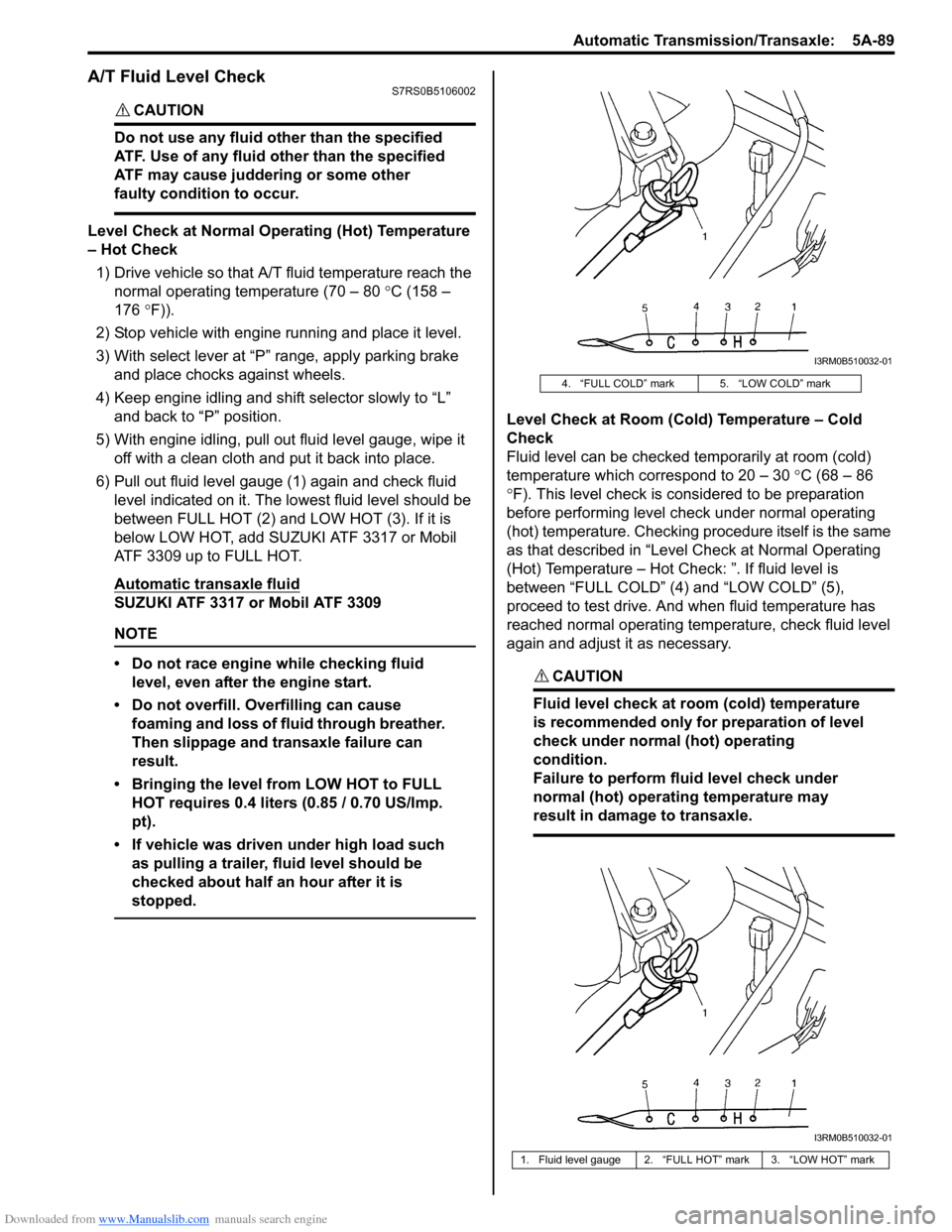
Level Check at Normal Operating (Hot) Temperature
– Hot Check1) Drive vehicle so that A/T fluid temperature reach the
normal operating temperature (70 – 80 °C (158 –
176 °F)).
2) Stop vehicle with engine running and place it level.
3) With select lever at “P” range, apply parking brake and place chocks against wheels.
4) Keep engine idling and shift selector slowly to “L” and back to “P” position.
5) With engine idling, pull out fluid level gauge, wipe it off with a clean cloth and put it back into place.
6) Pull out fluid level gauge (1) again and check fluid level indicated on it. The lo west fluid level should be
between FULL HOT (2) and LOW HOT (3). If it is
below LOW HOT, add SUZUKI ATF 3317 or Mobil
ATF 3309 up to FULL HOT.
Automatic transaxle fluid
SUZUKI ATF 3317 or Mobil ATF 3309
NOTE
• Do not race engine while checking fluid level, even after the engine start.
• Do not overfill. Overfilling can cause foaming and loss of fluid through breather.
Then slippage and transaxle failure can
result.
• Bringing the level from LOW HOT to FULL HOT requires 0.4 liters (0.85 / 0.70 US/Imp.
pt).
• If vehicle was driven under high load such as pulling a trailer, fluid level should be
checked about half an hour after it is
stopped.
Level Check at Room (Cold) Temperature – Cold
Check
Fluid level can be checked temporarily at room (cold)
temperature which correspond to 20 – 30 °C (68 – 86
° F). This level check is considered to be preparation
before performing level check under normal operating
(hot) temperature. Checking procedure itself is the same
as that described in “Level Check at Normal Operating
(Hot) Temperature – Hot Check: ”. If fluid level is
between “FULL COLD” (4) and “LOW COLD” (5),
proceed to test drive. And when fluid temperature has
reached normal operating temp erature, check fluid level
again and adjust it as necessary.
CAUTION!
Fluid level check at room (cold) temperature
is recommended only for preparation of level
check under normal (hot) operating
condition.
Failure to perform fluid level check under
normal (hot) operating temperature may
result in damage to transaxle.
4. “FULL COLD” mark 5. “LOW COLD” mark
1. Fluid level gauge 2. “FULL HOT” mark 3. “LOW HOT” mark
I3RM0B510032-01
I3RM0B510032-01
Page 815 of 1496
Downloaded from www.Manualslib.com manuals search engine Manual Transmission/Transaxle: 5B-1
Transmission / Transaxle
Manual Transmission/Transaxle
General Description
Manual Transaxle Construction and ServicingS7RS0B5201001
The transaxle provides five forward speeds and one reverse speed by means of three synchromeshs and three shafts
(input shaft, countershaft and reverse gear shaft). All forward gears are in constant mesh, and reverse uses a sliding
idler gear arrangement.
The low speed synchronizer sleeve & hub is mounted on countershaft and engaged with countershaft 1st gear or 2nd
gear, while the high speed synchronizer sleeve & hub is don e on input shaft and engaged with input shaft 3rd gear or
4th gear. The 5th speed synchronizer sleev e & hub on input shaft is engaged with input shaft fifth gear mounted on the
input shaft.
To prevent the cracking noise from the reverse gear when shifting transaxle gear into the reverse gear, the reverse
shift braking device is used.
The device utilizes the 5th synchromesh, which is the lever synchro type, to appl y the brake on the input shaft rotation.
The double cone synchronizing mechanism is provided to 2nd gear synchromesh device for high performance of
shifting to 2nd gear.
The countershaft turns the final gear and differential assembly, thereby turning the front drive shafts which are
attached to the front wheels.
For servicing, it is ne cessary to use genuine sealant or its equivalent on mating surfaces of transaxle case which is
made of aluminum. The case fastening bolts must be tight ened to specified torque by means of torque wrench. It is
also important that all parts are thoroughly cleaned with cleaning fluid and air dried before reassembling.
Further, care must be taken to adjust preload of count ershaft taper roller bearings. New synchronizer rings are
prohibited from being lapped with respective gear cones by using lapping compound before they are assembled.
Page 835 of 1496
Downloaded from www.Manualslib.com manuals search engine Manual Transmission/Transaxle: 5B-21
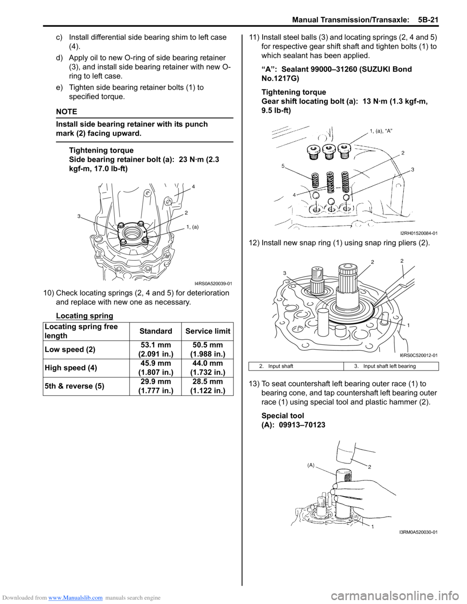
c) Install differential side bearing shim to left case (4).
d) Apply oil to new O-ring of side bearing retainer (3), and install side bea ring retainer with new O-
ring to left case.
e) Tighten side bearing retainer bolts (1) to specified torque.
NOTE
Install side bearing retainer with its punch
mark (2) facing upward.
Tightening torque
Side bearing retainer bolt (a): 23 N·m (2.3
kgf-m, 17.0 lb-ft)
10) Check locating springs (2, 4 and 5) for deterioration and replace with new one as necessary.
Locating spring
11) Install steel balls (3) and locating springs (2, 4 and 5) for respective gear shift shaft and tighten bolts (1) to
which sealant has been applied.
“A”: Sealant 99000–31260 (SUZUKI Bond
No.1217G)
Tightening torque
Gear shift locating bolt (a): 13 N·m (1.3 kgf-m,
9.5 lb-ft)
12) Install new snap ring (1) using snap ring pliers (2).
13) To seat countershaft left bearing outer race (1) to bearing cone, and tap countershaft left bearing outer
race (1) using special tool and plastic hammer (2).
Special tool
(A): 09913–70123
Locating spring free
length
Standard Service limit
Low speed (2) 53.1 mm
(2.091 in.) 50.5 mm
(1.988 in.)
High speed (4) 45.9 mm
(1.807 in.) 44.0 mm
(1.732 in.)
5th & reverse (5) 29.9 mm
(1.777 in.) 28.5 mm
(1.122 in.)
1, (a)
2
4
3
I4RS0A520039-01
2. Input shaft 3. Input shaft left bearing
I2RH01520084-01
1
2
2
3
I6RS0C520012-01
I3RM0A520030-01
Page 875 of 1496
Downloaded from www.Manualslib.com manuals search engine Steering Wheel and Column: 6B-4
Steering Wheel Removal and InstallationS7RS0B6206002
CAUTION!
Do not turn the contact coil more than
allowable number of turns (about two and a
half turns from the center position clockwise
or counterclockwise respectively) with
steering wheel removed, or coil will break.
Removal
CAUTION!
Do not hammer the end of the shaft.
Hammering it will loosen the plastic shear
pins which maintain the column length and
impair the collapsible design of the column.
1) Disconnect negative (–) cable at battery.
2) Disable air bag system referring to “Disabling Air
Bag System in Section 8B”.
3) Remove driver air bag (inflator) module from steering wheel. Refer to “Driver Air Bag (Inflator)
Module Removal and Installation in Section 8B”.
4) Disconnect horn connector and audio control switch connector, if equipped.
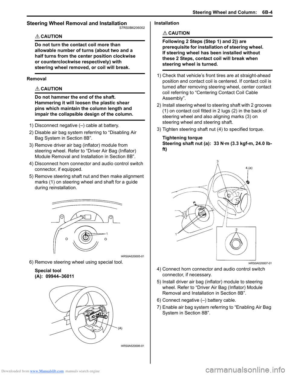
5) Remove steering shaft nut and then make alignment marks (1) on steering wheel and shaft for a guide
during reinstallation.
6) Remove steering wheel using special tool. Special tool
(A): 09944–36011 Installation
CAUTION!
Following 2 Steps (Step 1) and 2)) are
prerequisite for installation of steering wheel.
If steering wheel has
been installed without
these 2 Steps, contact coil will break when
steering wheel is turned.
1) Check that vehicle’s front tires are at straight-ahead position and contact coil is centered. If contact coil is
turned after removing steering wheel, center contact
coil referring to “Centering Contact Coil Cable
Assembly”.
2) Install steering wheel to steering shaft with 2 grooves (1) on contact coil fitted in 2 lugs (2) in the back of
steering wheel and also aligning marks (3) on
steering wheel and steering shaft.
3) Tighten steering shaft nut (4) to specified torque.
Tightening torque
Steering shaft nut (a): 33 N·m (3.3 kgf-m, 24.0 lb-
ft)
4) Connect horn connector and audio control switch connector, if necessary.
5) Install driver air bag (inflator) module to steering wheel. Refer to “Driver Air Bag (Inflator) Module
Removal and Installati on in Section 8B”.
6) Connect negative (–) battery cable.
7) Enable air bag system refe rring to “Enabling Air Bag
System in Section 8B”.
I4RS0A620005-01
(A)
I4RS0A620006-01
I4RS0A620007-01
Page 876 of 1496
Downloaded from www.Manualslib.com manuals search engine 6B-5 Steering Wheel and Column:
Contact Coil Cable Assembly Removal and
Installation
S7RS0B6206003
CAUTION!
Do not turn contact coil more than allowable
number of turns (about two and a half turns
from the center position clockwise or
counterclockwise respectively), or coil will
break.
Removal
1) Disconnect negative (–) cable at battery.
2) Disable air bag system referring to “Disabling Air Bag System in Section 8B”.
3) Remove steering wheel from steering column referring to “Steering Wheel Removal and
Installation”.
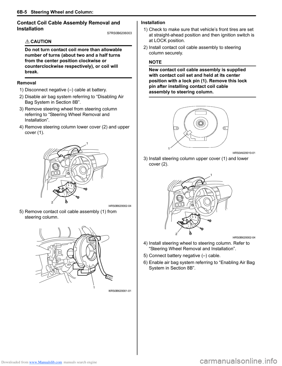
4) Remove steering column lower cover (2) and upper cover (1).
5) Remove contact coil cable assembly (1) from steering column. Installation
1) Check to make sure that vehicle’s front tires are set
at straight-ahead position and then ignition switch is
at LOCK position.
2) Install contact coil cable assembly to steering column securely.
NOTE
New contact coil cable assembly is supplied
with contact coil set and held at its center
position with a lock pin (1). Remove this lock
pin after installing contact coil cable
assembly to steering column.
3) Install steering column upper cover (1) and lower cover (2).
4) Install steering wheel to steering column. Refer to
“Steering Wheel Removal and Installation”.
5) Connect battery negative (–) cable.
6) Enable air bag system refe rring to “Enabling Air Bag
System in Section 8B”.
2
1
I4RS0B620002-04
1I6RS0B620001-01
I4RS0A620010-01
2
1
I4RS0B620002-04