2005 SUZUKI SWIFT steering
[x] Cancel search: steeringPage 613 of 1496

Downloaded from www.Manualslib.com manuals search engine Electronic Stability Program: 4F-39
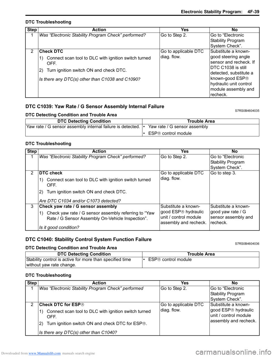
DTC Troubleshooting
DTC C1039: Yaw Rate / G Sensor Assembly Internal FailureS7RS0B4604035
DTC Detecting Condition and Trouble Area
DTC Troubleshooting
DTC C1040: Stability Control System Function FailureS7RS0B4604036
DTC Detecting Condition and Trouble Area
DTC TroubleshootingStep Action Yes No
1 Was “Electronic Stability Pr ogram Check” performed? Go to Step 2. Go to “Electronic
Stability Program
System Check”.
2 Check DTC
1) Connect scan tool to DLC with ignition switch turned
OFF.
2) Turn ignition switch ON and check DTC.
Is there any DTC(s) other than C1038 and C1090? Go to applicable DTC
diag. flow.
Substitute a known-
good steering angle
sensor and recheck. If
DTC C1038 is still
detected, substitute a
known-good ESP
®
hydraulic unit control
module assembly and
recheck.
DTC Detecting Condition Trouble Area
Yaw rate / G sensor as sembly internal failure is detect ed. • Yaw rate / G sensor assembly
• ESP ® control module
Step Action YesNo
1 Was “Electronic Stability Pr ogram Check” performed? Go to Step 2.Go to “Electronic
Stability Program
System Check”.
2 DTC check
1) Connect scan tool to DLC with ignition switch turned
OFF.
2) Turn ignition switch ON and check DTC.
Are DTC C1034 and/or C1073 detected? Go to applicable DTC
diag. flow.
Go to step 3.
3 Check yaw rate / G sensor assembly
1) Check yaw rate / G sensor assembly referring to “Yaw
Rate / G Sensor Assembly On-Vehicle Inspection”.
Is it good condition? Substitute a known-
good ESP
® hydraulic
unit / control module
assembly and recheck. Substitute a known-
good yaw rate / G
sensor assembly and
recheck.
DTC Detecting Condition
Trouble Area
Stability control is active fo r more than specified time
without yaw rate change. • ESP
® control module
Step Action YesNo
1 Was “Electronic Stability Pr ogram Check” performed Go to Step 2.Go to “Electronic
Stability Program
System Check”.
2 Check DTC for ESP ®
1) Connect scan tool to DLC with ignition switch turned OFF.
2) Turn ignition switch ON and check DTC for ESP ®.
Is there any DTC(s) other than C1040? Go to applicable DTC
diag. flow.
Substitute a known-
good ESP
® hydraulic
unit / control module
assembly and recheck.
Page 620 of 1496

Downloaded from www.Manualslib.com manuals search engine 4F-46 Electronic Stability Program:
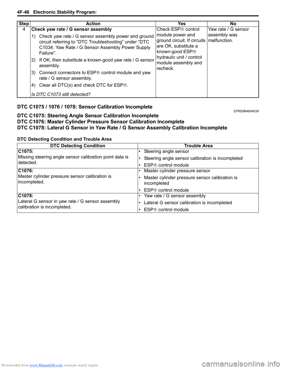
DTC C1075 / 1076 / 1078: Sensor Calibration IncompleteS7RS0B4604039
DTC C1075: Steering Angle Sensor Calibration Incomplete
DTC C1076: Master Cylinder Pressure Sensor Calibration Incomplete
DTC C1078: Lateral G Sensor in Yaw Rate / G Sensor Assembly Calibration Incomplete
DTC Detecting Condition and Trouble Area4
Check yaw rate / G sensor assembly
1) Check yaw rate / G sensor assembly power and ground
circuit referring to “DTC Troubleshooting” under “DTC
C1034: Yaw Rate / G Sensor Assembly Power Supply
Failure”.
2) If OK, then substitute a known-good yaw rate / G sensor assembly.
3) Connect connectors to ESP ® control module and yaw
rate / G sensor assembly.
4) Clear all DTC(s) and check DTC for ESP ®.
Is DTC C1073 still detected? Check ESP
® control
module power and
ground circuit. If circuits
are OK, substitute a
known-good ESP ®
hydraulic unit / control
module assembly and
recheck. Yaw rate / G sensor
assembly was
malfunction.
Step Action Yes No
DTC Detecting Condition
Trouble Area
C1075:
Missing steering angle sensor calibration point data is
detected. • Steering angle sensor
• Steering angle sensor ca
libration is incompleted
• ESP ® control module
C1076:
Master cylinder pressure sensor calibration is
incompleted. • Master cylinder pressure sensor
• Master cylinder pressure sensor calibration is
incompleted
• ESP ® control module
C1078:
Lateral G sensor in yaw ra te / G sensor assembly
calibration is incompleted. • Yaw rate / G sensor assembly
• Lateral G sensor calibration is incompleted
• ESP
® control module
Page 621 of 1496

Downloaded from www.Manualslib.com manuals search engine Electronic Stability Program: 4F-47
DTC Troubleshooting
DTC C1090: Invalid Communication with ECMS7RS0B4604040
DTC Detecting Condition and Trouble Area
DTC TroubleshootingStep Action Yes No
1 Was “Electronic Stability Pr ogram Check” performed? Go to Step 2. Go to “Electronic
Stability Program
System Check”.
2 DTC check for ESP®
1) Connect scan tool to DLC with ignition switch turned
OFF.
2) Turn ignition switch ON and check DTC for ESP ®.
Is there any DTC(s) other than C1075, C1076 and C1078? Go to applicable DTC
diag. flow.
Go to Step 3.
3 Check sensor calibration
1) Calibrate all sens ors referring to “Sensor Calibration”.
2) Clear all DTC(s) and check DTC for ESP ®.
Is DTC C1075, C1076 and/ or C1078 still detected? DTC C1075: Substitute
a known-good steering
angle sensor and
recheck.
DTC C1076: Substitute
a known-good ESP
®
hydraulic unit / control
module assembly and
recheck.
DTC C1078: Substitute
a known-good yaw rate
/ G sensor assembly
and recheck. Calibration was
incompleted.
DTC Detecting Condition
Trouble Area
ESP ® control module rolling counte r failure is detected by
ECM. • CAN communication circuit
•ECM
• ESP
® control module
Step Action YesNo
1 Was “Electronic Stability Pr ogram Check” performed? Go to Step 2.Go to “Electronic
Stability Program
System Check”.
2 DTC check for ESP®
1) Connect scan tool to DLC with ignition switch turned
OFF.
2) Turn ignition switch ON and check DTC for ESP ®.
Is there any DTC(s) other than C1038 and C1090? Go to applicable DTC
diag. flow.
Go to Step 3.
3 DTC check for ECM
1) Check DTC for ECM.
Is DTC P1674 and/or DTC P1685 detected? Go to applicable DTC
diag. flow.
Substitute a known-
good ESP
® hydraulic
unit / control module
assembly and recheck.
Page 623 of 1496

Downloaded from www.Manualslib.com manuals search engine Electronic Stability Program: 4F-49
DTC U1073: Control Module Communication Bus OffS7RS0B4604057
Wiring Diagram
DTC Detecting Condition and Trouble Area
E85-13E85-44
E46-2E46-1
G37-4G37-2
E85-46E85-42
E23-3E23-18
G50-9G50-10
G28-8G28-10
G28-9G28-7
G42-19G42-18
REDWHT
WHTRED
WHTRED
REDWHT
REDWHT
WHTRED
REDWHT
REDWHT
REDWHT
[A]
21
E2334
1819
5671011
17
20
47 46
495051
2122
52 16
25 9
24
14
29
5557 54 53
59
60 5826
27
28
15
30
56 4832 31343536374042 39 38
44
45 43 41 33
1213
238
G42[F]
1234567891011
141516
36 34 33 32 31 30 29 24 23
37
181920
[B]
E85
161
15
2
3
4
5
6
7
8
9
10
11
12
13
14
17
18
19
20
21
22
23
24
25
26
27
28
29
30
31
3233
34
35
36
37
38
39
40
41
42
43
44
45
46
47 [C]
G37
E46
124
53
67
891011121314124
53
67
891011
1213141516171819202122
[E] G28
12345678910111213141516
17181920212223242526272829303132
[D] G50
109 321
4
5
7 1
2
3
6
I7RS0B460011-02
[A]: ECM connector (viewed from harness side) [F]: Keyless start control module
connector (viewed from
harness side) 5. Combination meter
[B]: ESP ® control module connector (viewed from
terminal side) 1. ECM
6. Keyless start control module (if equipped)
[C]: BCM connector (viewed from harness side) 2. ESP® hydraulic unit / control
module assembly 7. Junction connector
[D]: Steering angle sensor connector (viewed from harness side) 3. BCM
[E]: Combination meter connector (viewed from harness side) 4. Steering angle sensor
DTC Detecting Condition
Trouble Area
Transmission error that is inconsistent between
transmission data and transmission monitor (CAN bus
monitor) data is detected more than 7 times continuously. • CAN communication circuit
•ECM
• ESP
® control module
•BCM
• Steering angle sensor
• Combination meter
• Keyless start control module (if equipped)
Page 624 of 1496

Downloaded from www.Manualslib.com manuals search engine 4F-50 Electronic Stability Program:
DTC Troubleshooting
DTC U1100: Lost Communication with ECM (Reception Error)S7RS0B4604058
Wiring Diagram
Refer to “Wiring Diagram” under “DTC U1073: Control Module Communication Bus Off”.
DTC Detecting Condition and Trouble Area
DTC TroubleshootingStep Action Yes No
1 Was “Electronic Stability Pr ogram Check” performed? Go to Step 2. Go to “Electronic
Stability Program
System Check”.
2 DTC check for ESP®
1) Check connection of connectors of all control modules
communicating by means of CAN.
2) Recheck DTC for ESP ®.
Is DTC U1073 indicated? Go to Step 3. Intermittent trouble.
Check for intermittent
referring to “Intermittent
and Poor Connection
Inspection in Section
00”.
3 CAN communication circuit check
1) Turn ignition switch to OFF position.
2) Disconnect connectors of all control modules
communicating by means of CAN.
3) Check CAN communication circuit between control modules for open, short and high resistance.
Is each CAN communication circuit in good condition? Go to Step 4. Repair or replace the
CAN communication
line.
4 DTC check for ESP®
1) Connect connectors of disconnected control modules
communicating by means of CAN.
2) Disconnect each connector. •ECM
• Keyless start control module (if equipped)
• Combination meter
• Steering angle sensor
•BCM
3) Recheck DTC for ESP ®.
Is DTC U1073 detected? Check ESP
® control
module power and
ground circuit. If circuits
are OK, substitute a
known-good ESP ®
hydraulic unit / control
module assembly and
recheck. Check applicable
control module power
and ground circuit. If
circuit is OK, substitute
a known-good
applicable control
module and recheck.
DTC Detecting Condition
Trouble Area
ECM message data is missing from CAN communication. • CAN communication circuit
•ECM
• ESP® control module
Step Action YesNo
1 Was “Electronic Stability Pr ogram Check” performed? Go to Step 2.Go to “Electronic
Stability Program
System Check”.
2 DTC check for ESP®
1) Check DTC for ESP ®.
Is DTC U1100 and DTC U1073 detected together? Go to “DTC U1073:
Control Module
Communication Bus
Off”.Go to Step 3.
3 DTC check for ECM
1) Check DTC for ECM.
Is DTC P1674 detected? Go to “DTC P1674:
CAN Communication
(Bus Off Error) in
Section 1A”.Go to Step 4.
Page 625 of 1496

Downloaded from www.Manualslib.com manuals search engine Electronic Stability Program: 4F-51
DTC U1126: Lost Communication with Steering Angle Sensor (Reception Error)S7RS0B4604043
Wiring Diagram
Refer to “Wiring Diagram” under “DTC U1073: Control Module Communication Bus Off”.
DTC Detecting Condition and Trouble Area
DTC Troubleshooting4
Check each control module connectors
1) Check connection of connectors of all control modules
communicating by means of CAN.
2) Check DTC for ESP ®.
Is DTC U1100 detected? Go to Step 5. Check for intermittent
trouble referring to
“Intermittent and Poor
Connection Inspection
in Section 00”.
5 CAN communication circuit check
1) Turn ignition switch to OFF position.
2) Disconnect connectors of ESP ® control module and
ECM communicating by means of CAN.
3) Check CAN communication circuit between ESP®
control module and ECM for open, short and high
resistance.
Is each CAN communication circuit in good condition? Repair or replace the
CAN communication
line.
Go to Step 6.
6 CAN communication circuit check
1) Disconnect connectors of all control modules
communicating by means of CAN.
2) Check CAN communication circuit between control modules other than Step 5 for open, short and high
resistance.
Is each CAN communication circuit in good condition? Go to Step 7. Repair or replace the
CAN communication
line.
7 DTC check for ESP®
1) Connect connectors of disconnected control modules
communicating by means of CAN.
2) Disconnect each connector. •ECM
• Keyless start control module (if equipped)
• Combination meter
• Steering angle sensor
•BCM
3) Recheck DTC for ESP ®.
Is DTC U1100 detected? Check ESP
® control
module power and
ground circuit. If circuits
are OK, substitute a
known-good ESP ®
hydraulic unit / control
module assembly and
recheck. Check applicable
control module power
and ground circuit. If
circuit is OK, substitute
a known-good
applicable control
module and recheck.
Step Action Yes No
DTC Detecting Condition
Trouble Area
Steering angle sensor message data is missing from CAN
communication. • CAN communication circuit
• Steering angle sensor
• ESP
® control module
Step Action YesNo
1 Was “Electronic Stability Pr ogram Check” performed? Go to Step 2.Go to “Electronic
Stability Program
System Check”.
2 DTC check for ESP®
1) Check DTC for ESP ®.
Is DTC U1126 and DTC U1073 detected together? Go to “DTC U1073:
Control Module
Communication Bus
Off”.Go to Step 3.
Page 626 of 1496

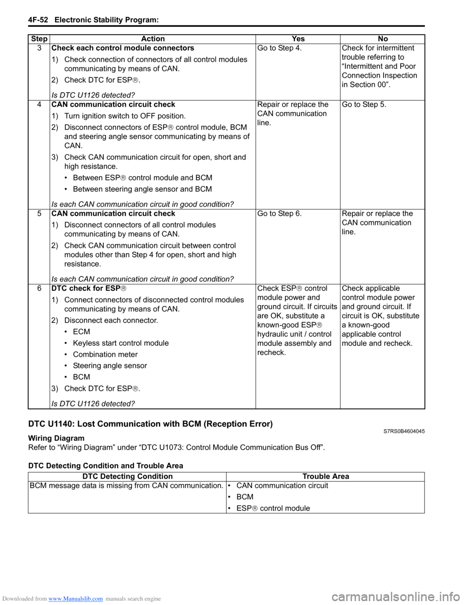
Downloaded from www.Manualslib.com manuals search engine 4F-52 Electronic Stability Program:
DTC U1140: Lost Communication with BCM (Reception Error)S7RS0B4604045
Wiring Diagram
Refer to “Wiring Diagram” under “DTC U1073: Control Module Communication Bus Off”.
DTC Detecting Condition and Trouble Area3
Check each control module connectors
1) Check connection of connectors of all control modules
communicating by means of CAN.
2) Check DTC for ESP ®.
Is DTC U1126 detected? Go to Step 4. Check for intermittent
trouble referring to
“Intermittent and Poor
Connection Inspection
in Section 00”.
4 CAN communication circuit check
1) Turn ignition switch to OFF position.
2) Disconnect connectors of ESP ® control module, BCM
and steering angle sensor communicating by means of
CAN.
3) Check CAN communication circuit for open, short and high resistance.
• Between ESP ® control module and BCM
• Between steering angle sensor and BCM
Is each CAN communication circuit in good condition? Repair or replace the
CAN communication
line.
Go to Step 5.
5 CAN communication circuit check
1) Disconnect connectors of all control modules
communicating by means of CAN.
2) Check CAN communication circuit between control modules other than Step 4 for open, short and high
resistance.
Is each CAN communication circuit in good condition? Go to Step 6. Repair or replace the
CAN communication
line.
6 DTC check for ESP®
1) Connect connectors of disconnected control modules
communicating by means of CAN.
2) Disconnect each connector. •ECM
• Keyless start control module
• Combination meter
• Steering angle sensor
•BCM
3) Check DTC for ESP ®.
Is DTC U1126 detected? Check ESP
® control
module power and
ground circuit. If circuits
are OK, substitute a
known-good ESP ®
hydraulic unit / control
module assembly and
recheck. Check applicable
control module power
and ground circuit. If
circuit is OK, substitute
a known-good
applicable control
module and recheck.
Step Action Yes No
DTC Detecting Condition
Trouble Area
BCM message data is missing from CAN communication. • CAN communication circuit
•BCM
• ESP® control module
Page 627 of 1496

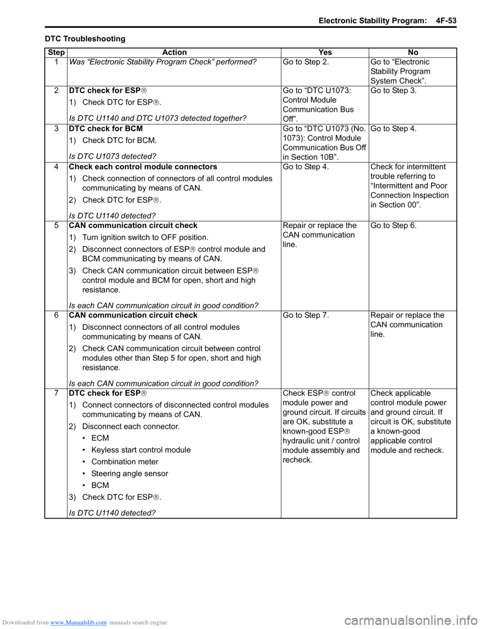
Downloaded from www.Manualslib.com manuals search engine Electronic Stability Program: 4F-53
DTC TroubleshootingStep Action Yes No 1 Was “Electronic Stability Pr ogram Check” performed? Go to Step 2. Go to “Electronic
Stability Program
System Check”.
2 DTC check for ESP®
1) Check DTC for ESP ®.
Is DTC U1140 and DTC U1073 detected together? Go to “DTC U1073:
Control Module
Communication Bus
Off”.Go to Step 3.
3 DTC check for BCM
1) Check DTC for BCM.
Is DTC U1073 detected? Go to “DTC U1073 (No.
1073): Control Module
Communication Bus Off
in Section 10B”.Go to Step 4.
4 Check each control module connectors
1) Check connection of connectors of all control modules
communicating by means of CAN.
2) Check DTC for ESP ®.
Is DTC U1140 detected? Go to Step 4. Check for intermittent
trouble referring to
“Intermittent and Poor
Connection Inspection
in Section 00”.
5 CAN communication circuit check
1) Turn ignition switch to OFF position.
2) Disconnect connectors of ESP ® control module and
BCM communicating by means of CAN.
3) Check CAN communication circuit between ESP®
control module and BCM for open, short and high
resistance.
Is each CAN communication circuit in good condition? Repair or replace the
CAN communication
line.
Go to Step 6.
6 CAN communication circuit check
1) Disconnect connectors of all control modules
communicating by means of CAN.
2) Check CAN communication circuit between control modules other than Step 5 for open, short and high
resistance.
Is each CAN communication circuit in good condition? Go to Step 7. Repair or replace the
CAN communication
line.
7 DTC check for ESP®
1) Connect connectors of disconnected control modules
communicating by means of CAN.
2) Disconnect each connector. •ECM
• Keyless start control module
• Combination meter
• Steering angle sensor
•BCM
3) Check DTC for ESP ®.
Is DTC U1140 detected? Check ESP
® control
module power and
ground circuit. If circuits
are OK, substitute a
known-good ESP ®
hydraulic unit / control
module assembly and
recheck. Check applicable
control module power
and ground circuit. If
circuit is OK, substitute
a known-good
applicable control
module and recheck.