2005 SUZUKI SWIFT rear brake
[x] Cancel search: rear brakePage 811 of 1496

Downloaded from www.Manualslib.com manuals search engine Automatic Transmission/Transaxle: 5A-167
Specifications
Tightening Torque SpecificationsS7RS0B5107001
NOTE
The specified tightening torque is also described in the following.
“Select Cable Components”
“Automatic Transaxle Unit Components”
“Automatic Transaxle Assembly Components”
“Oil Pump Assembly Components”
“Transaxle Rear Cover (O/D and 2nd Coast Brake Piston) Assembly Components”
“Valve Body Assembly Components”
“Differential Assembly Components”
Reference:
For the tightening torque of fastener not specified in this section, refer to “Fasteners Information in Section 0A”.
Fastening part
Tightening torque
Note
N ⋅mkgf-mlb-ft
A/T fluid drain plug 171.7 12.5 �) / �) / �)
Transmission range sensor bolt 5.5 0.55 4.0�) / �)
Output shaft speed sensor bolt 131.3 9.5 �) / �)
Input shaft speed sensor bolt 5.5 0.55 4.0�)
Valve body harness connector bolt 7.00.7 5.0 �)
Shift solenoid bolt 111.1 8.0 �)
Oil strainer bolt 101.0 7.5 �) / �)
Oil pan bolt 7.00.7 5.0 �) / �)
Transaxle and engine fastening bolt and nut 85 8.5 61.5�)
Drive plate to torque converter bolt 252.5 18.0 �)
Transaxle stiffener bolt 555.5 40�)
Starter motor bolt and nut 505.0 36.5 �)
Oil pump subassembly bolt 101.0 7.5 �)
Rear cover plug 7.5 0.75 5.5�)
Solenoid valve bolt 111.1 8.0 �)
Final gear bolt 787.8 56.5 �)
Torque converter housing plug 7.5 0.75 5.5�)
Lubrication tube clamp bolt 5.5 0.55 4.0�)
Fluid reservoir RH plate bolt 5.5 0.55 4.0�)
Torque converter housing bolt 292.9 21�) / �) / �)
Manual detent spring bolt 101.0 7.5 �)
Parking lock pawl bracket bolt 7.5 0.75 5.5�)
Rear cover bolt 252.5 18.0 �)
Fluid reservoir LH plate bolt 101.0 7.5 �)
Oil pump assembly bolt 252.5 18.0 �)
Transaxle case plug 7.5 0.75 5.5�)
Valve body harness connector bolt 5.5 0.55 4.0�)
Valve body bolt 111.1 8.0 �)
Fluid outlet union 252.5 18.0 �)
Fluid cooler pipe union bolt 222.2 16.0 �)
Fluid cooler pipe bracket bolt 101.0 7.5 �)
Fluid filler tube bolt 101.0 7.5 �)
Input shaft speed sensor bolt 111.1 8.0 �)
Harness bracket bolt 232.3 17.0 �)
Select cable clamp bolt 101.0 7.5 �)
Transmission range sensor lock nut 70.7 5.0 �)
Manual select lever nut 131.3 9.5 �)
Engine mounting LH bracket bolt 555.5 40.0
�)
Page 812 of 1496
Downloaded from www.Manualslib.com manuals search engine 5A-168 Automatic Transmission/Transaxle:
Special Tools and Equipment
Recommended Service MaterialS7RS0B5108001
NOTE
Required service material is also described in the following.
“Select Cable Components”
“Automatic Transaxle Unit Components”
“Automatic Transaxle Assembly Components”
“Oil Pump Assembly Components”
“Direct Clutch Assembly Components”
“Forward and Reverse Clutch Assembly Components”
“2nd Brake Piston Assembly Components”
“Transaxle Rear Cover (O/D and 2nd Coast Brake Piston) Assembly Components”
“Countershaft Assembly Components”
“Valve Body Assembly Components”
“Differential Assembly Components”
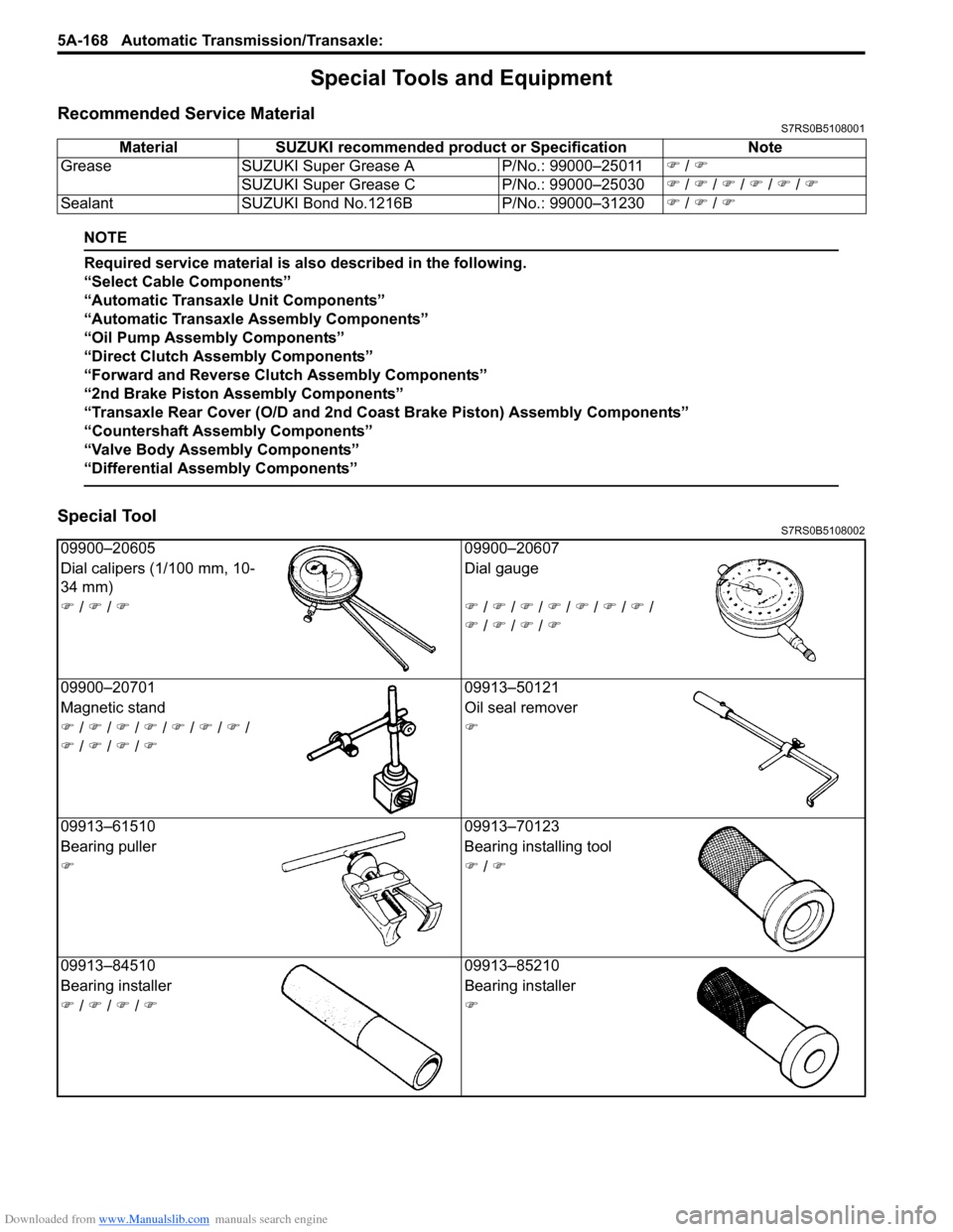
Special ToolS7RS0B5108002
Material SUZUKI recommended product or Specification Note
Grease SUZUKI Super Grease A P/No.: 99000–25011�) / �)
SUZUKI Super Grease C P/No.: 99000–25030�) / �) / �) / �) / �) / �)
Sealant SUZUKI Bond No.1216B P/No.: 99000–31230�) / �) / �)
09900–20605 09900–20607
Dial calipers (1/100 mm, 10-
34 mm) Dial gauge
�) / �) / �)�) / �) / �) / �) / �) / �) / �) /
�) / �) / �) / �)
09900–20701 09913–50121
Magnetic stand Oil seal remover
�) / �) / �) / �) / �) / �) / �) /
�) / �) / �) / �) �)
09913–61510 09913–70123
Bearing puller Bearing installing tool
�)�) / �)
09913–84510 09913–85210
Bearing installer Bearing installer
�) / �) / �) / �)�)
Page 1167 of 1496

Downloaded from www.Manualslib.com manuals search engine Table of Contents 9- i
9
Section 9
CONTENTS
Body, Cab and Accessories
Precautions ................................................. 9-1
Precautions............................................................. 9-1
Precautions on Body, Cab and Accessories ......... 9-1
Precautions for Body Service ................................ 9-1
Fastener Caution for Body Service ....................... 9-1
Wiring Systems............... ......................... 9A-1
Precautions........................................................... 9A-1
Cautions in Body Electrical System Servicing..... 9A-1
General Description ............................................. 9A-1 Abbreviations ...................................................... 9A-1
Wire / Connector Color Sy mbols ......................... 9A-1
Symbols and Marks ............................................ 9A-2
How to Read Connector Layout Diagram ........... 9A-4
How to Read Connector Codes and Terminal Nos.................................................................... 9A-5
How to Read Ground Point ................................. 9A-7
How to Read Power Supply Diagram.................. 9A-8
How to Read System Circuit Diagram................. 9A-8
Connector Layout Diagram . .............................. 9A-10
Connector Layout Diagram ............................... 9A-10
Engine Compartment .......... .............................. 9A-10
Instrument Panel ............................................... 9A-16
Door, Roof......................................................... 9A-20
Floor .................................................................. 9A-23
Rear .................................................................. 9A-29
Ground Point ...................................................... 9A-30 Ground (earth) Point ......................................... 9A-30
Power Supply Diagram ........ .............................. 9A-31
Power Supply Diagram ....... .............................. 9A-31
Fuses and the Protected Parts ......................... 9A-33
Fuses in Main Fuse Box (RHD) ........................ 9A-33
Fuses in Main Fuse Box (LHD) ......................... 9A-33
Individual Circuit Fuse Box No. 1 ...................... 9A-34
Individual Circuit Fuse Box No. 2 (In J/B) ......... 9A-35
Junction Block (J/B) Connector / Fuse Layout .. 9A-37
Junction Block Inner Circuit (Overview) ............ 9A-38
Junction Block Inner Circuit (Detail) .................. 9A-40
System Circuit Diagram... .................................. 9A-45
System Circuit Diagram .. .................................. 9A-45
A-1 Cranking System Circ uit Diagram .............. 9A-46
A-2 Charging System Circu it Diagram .............. 9A-47
A-3 Ignition System Circu it Diagram ................. 9A-48
A-4 Cooling System Circuit Diagram................. 9A-49 A-5 Engine and A/C Control System Circuit
Diagram........................................................... 9A-50
A-6 A/T Control System Circuit Diagram........... 9A-55
A-7 Immobilizer System Circuit Diagram .......... 9A-57
A-8 Body Control System Circuit Diagram ........ 9A-58
B-1 Windshield Wiper and Washer Circuit Diagram........................................................... 9A-62
B-2 Rear Wiper and Washer Circuit Diagram ... 9A-63
B-3 Rear Defogger Circuit Diagram .................. 9A-64
B-4 Power Window Circuit Diagram .................. 9A-65
B-5 Power Door Lock Circu it Diagram .............. 9A-67
B-6 Power Mirror Circuit Diagram ..................... 9A-69
B-7 Horn Circuit Diagram .................................. 9A-70
B-8 Seat Heater Circuit Diagram....................... 9A-71
B-9 Keyless Start System Circuit Diagram........ 9A-72
C-1 Combination Mete r Circuit Diagram
(Meter)............................................................. 9A-73
C-2 Combination Mete r Circuit Diagram
(Indicator) ........................................................ 9A-74
C-3 Combination Mete r Circuit Diagram
(Warning Light)................................................ 9A-75
D-1 Headlight System Circuit Diagram ............. 9A-77
D-2 Position, Tail and Licence Plate Light System Circuit Diagram .................................. 9A-79
D-3 Front Fog Light System Circuit Diagram .... 9A-80
D-4 Illumination Light System Circuit Diagram .. 9A-81
D-5 Interior Light System Circuit Diagram......... 9A-82
D-6 Turn Signal and Hazard Warning Light System Circuit Diagram .................................. 9A-83
D-7 Brake Light System Circuit Diagram .......... 9A-85
D-8 Back-Up Light System Circuit Diagram ...... 9A-86
D-9 Headlight Beam Leveling System Circuit Diagram........................................................... 9A-87
D-10 Rear Fog Light Circuit Diagram ................ 9A-88
E-1 Heater System Circuit Diagram .................. 9A-89
E-2 Auto A/C System Circuit Diagram .............. 9A-91
F-1 Air-Bag System Circuit Diagram ................. 9A-93
F-2 Anti-Lock Brake System Circuit Diagram.... 9A-95
F-3 Electronic Stab ility Program System
Circuit Diagram .................. ............................. 9A-97
F-4 Power Steering System Circuit Diagram .... 9A-99
G-1 Audio System Circuit Diagram ................. 9A-101
G-2 Multi Information Display / Accessory Socket System Circuit Diagram .................... 9A-102
List of Connector .............................................9A-103
Page 1185 of 1496

Downloaded from www.Manualslib.com manuals search engine Wiring Systems: 9A-14
E: Main harness (RHD)
E: Main harness
56
E06E12
E03or
E85
E07
E09
E08
E13
E10
E11E05 E04
E01 E02
E19
7
22
E34E31
E32
E57
E24
(TO C36)
E33
E36
E35
E30
E29
E28
E20
E21
E22
E27
E26
E23
E25E17E56
E18
E14 E15
E55
E
I7RS0B910902-02
No./Color
Connective position No./ColorConnective position
E01/GRY Windshield wiper motor E22/N Front position light (L)
E02/GRY Brake fluid level switch E23/GRY ECM
E03/BLK ABS control module E24/N Engine Harness (To C36)
E04/BLK A/C pressure sensor E25/BLK Wheel speed sensor (FL)
E05/BLK Wheel speed sensor (FR) E26/N Main fuse box
E06/N Side turn signal light (R) E27/BLK Main fuse box
E07/N Front position light (R) E28/BLK Radiator fan relay #1
E08/BLK Head light (R) E29/BLK Radiator fan relay #2
E09/GRY Front turn signal light (R) E30/BLK Radiator fan relay #3
E10/GRN Rear washer motor E31/BLK Starting motor relay
E11/BLU Windshield washer motor E32/BLK Main relay
E12/BLK (IF EQPD) Front fog light (R)
E33/BLK A/T relay
E13/YEL Forward sensor E34/BLK (IF
EQPD) Front fog light relay
E14/BLK Outside air temperature sensor E35/BLK Fuel pump relay
E15/BLK Horn E36/BLK A/C compressor relay
E17/BLK Radiator fan motor E55/- Weld splice
E18/BLK (IF EQPD) Front fog light (L) E56/BLK
(M16A
engine) Throttle actuator control relay
E19/N Side turn signal light (L) E57/BLK Diagnosis connector #1
E20/GRY Front turn signal light (L) E85/BLK (IF
EQPD) ESP
® control module
E21/BLK Headlight (R)
Page 1186 of 1496
Downloaded from www.Manualslib.com manuals search engine 9A-15 Wiring Systems:
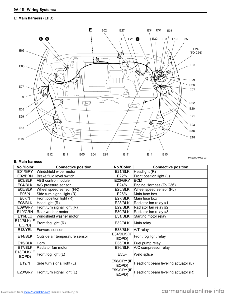
E: Main harness (LHD)
E: Main harness
56
E06E12
E
E03
E07
E09
E59E08
E13
E10
E11E05 E04
E01
E02E197
E34
E31
E32
E24
(TO C36)
E33
E36
E35
E30
E29
E28
E20
E21
E22
E58
E27
E26
E23
E25E17
E18
E14 E15
E55
I7RS0B910903-02
No./Color
Connective position No./ColorConnective position
E01/GRY Windshield wiper motor E21/BLK Headlight (R)
E02/BRN Brake fluid level switch E22/N Front position light (L)
E03/BLK ABS control module E23/GRY ECM
E04/BLK A/C pressure sensor E24/N Engine Harness (To C36)
E05/BLK Wheel speed sensor (FR) E25/BLK Wheel speed sensor (FL)
E06/N Side turn signal light (R) E26/N Main fuse box
E07/N Front position light (R) E27/BLK Main fuse box
E08/BLK Head light (R) E28/BLK Radiator fan relay #1
E09/GRY Front turn signal light (R) E29/BLK Radiator fan relay #2
E10/GRN Rear washer motor E30/BLK Radiator fan relay #3
E11/BLU Windshield washer motor E31/BLK Starting motor relay
E12/BLK (IF EQPD) Front fog light (R)
E32/BLK Main relay
E13/YEL Forward sensor E33/BLK A/T relay
E14/BLK Outside air temperature sensor E34/BLK (IF
EQPD) Front fog light relay
E15/BLK Horn E35/BLK Fuel pump relay
E17/BLK Radiator fan motor E36/BLK A/C compressor relay
E18/BLK (IF
EQPD) Front fog light (L)
E55/- Weld splice
E19/N Side turn signal light (L) E58/GRY (IF
EQPD) Headlight beam leveling actuator (L)
E20/GRY Front turn signal light (L) E59/GRY (IF
EQPD) Headlight beam leveling actuator (R)
Page 1195 of 1496
Downloaded from www.Manualslib.com manuals search engine Wiring Systems: 9A-24
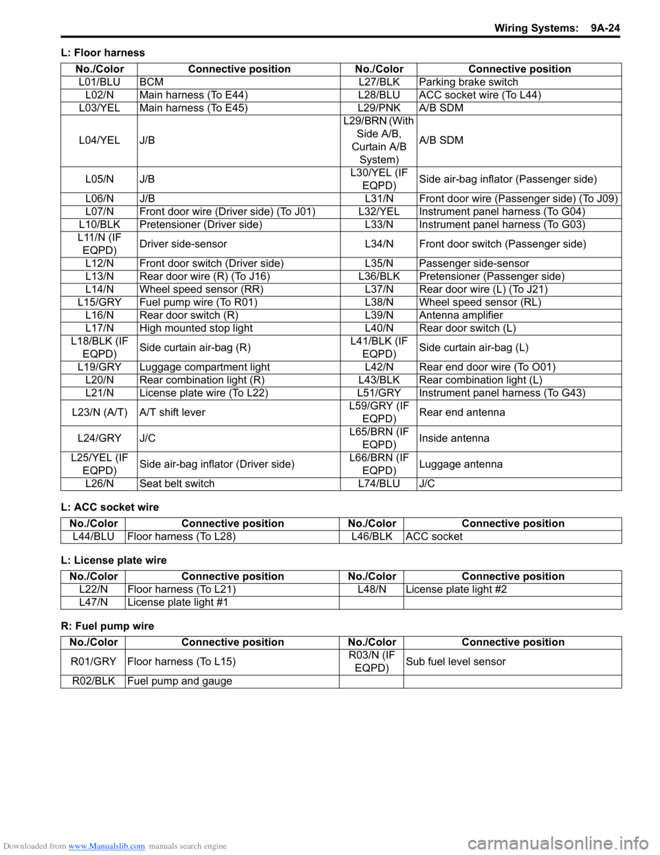
L: Floor harness
L: ACC socket wire
L: License plate wire
R: Fuel pump wireNo./Color Connective position No./Color Connective position
L01/BLU BCM L27/BLK Parking brake switch L02/N Main harness (To E44) L28/BLU ACC socket wire (To L44)
L03/YEL Main harness (To E45) L29/PNK A/B SDM
L04/YEL J/B L29/BRN (With
Side A/B,
Curtain A/B System) A/B SDM
L05/N J/B L30/YEL (IF
EQPD) Side air-bag inflator (Passenger side)
L06/N J/B L31/N Front door wire (Passenger side) (To J09)
L07/N Front door wire (Driver side) (To J01) L32/YEL Instrument panel harness (To G04)
L10/BLK Pretensioner (Driver side) L33/N Instrument panel harness (To G03)
L11/N (IF EQPD) Driver side-sensor L34/N Front door switch (Passenger side)
L12/N Front door switch (Driver side) L35/N Passenger side-sensor
L13/N Rear door wire (R) (To J16) L 36/BLK Pretensioner (Passenger side)
L14/N Wheel speed sensor (RR) L37/N Rear door wire (L) (To J21)
L15/GRY Fuel pump wire (To R01) L38/N Wheel speed sensor (RL)
L16/N Rear door switch (R) L39/N Antenna amplifier
L17/N High mounted stop light L40/N Rear door switch (L)
L18/BLK (IF EQPD) Side curtain air-bag (R) L41/BLK (IF
EQPD) Side curtain air-bag (L)
L19/GRY Luggage compartment light L42/N Rear end door wire (To O01) L20/N Rear combination light (R) L43/BLK Rear combination light (L)
L21/N License plate wire (To L22) L51/ GRY Instrument panel harness (To G43)
L23/N (A/T) A/T shift lever L59/GRY (IF
EQPD) Rear end antenna
L24/GRY J/C L65/BRN (IF
EQPD) Inside antenna
L25/YEL (IF EQPD) Side air-bag inflator (Driver side) L66/BRN (IF
EQPD) Luggage antenna
L26/N Seat belt switch L74/BLU J/C
No./Color Connective position No./Color Connective position
L44/BLU Floor harness (To L28) L46/BLK ACC socket
No./ColorConnective position No./Color Connective position
L22/N Floor harness (To L21) L48/N License plate light #2
L47/N License plate light #1
No./Color Connective position No./Color Connective position
R01/GRY Floor harness (To L15) R03/N (IF
EQPD) Sub fuel level sensor
R02/BLK Fuel pump and gauge
Page 1197 of 1496
Downloaded from www.Manualslib.com manuals search engine Wiring Systems: 9A-26
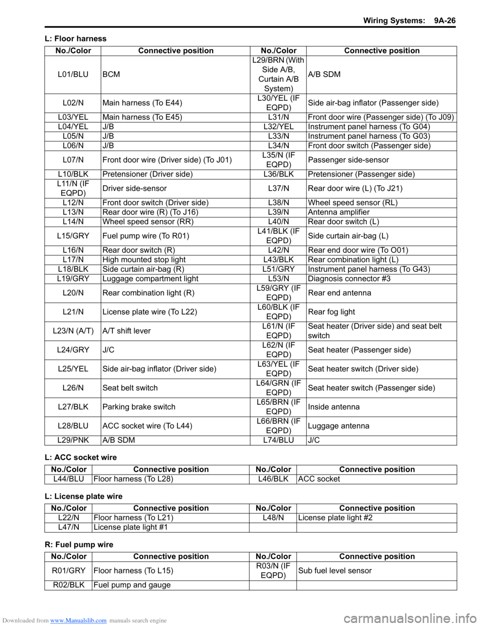
L: Floor harness
L: ACC socket wire
L: License plate wire
R: Fuel pump wireNo./Color Connective position No./Color Connective position
L01/BLU BCM L29/BRN (With
Side A/B,
Curtain A/B System) A/B SDM
L02/N Main harness (To E44) L30/YEL (IF
EQPD) Side air-bag inflator (Passenger side)
L03/YEL Main harness (To E45) L31/N Front door wire (Passenger side) (To J09)
L04/YEL J/B L32/YEL Instrument panel harness (To G04) L05/N J/B L33/N Instrument panel harness (To G03)
L06/N J/B L34/N Front door switch (Passenger side)
L07/N Front door wire (Driver side) (To J01) L35/N (IF
EQPD) Passenger side-sensor
L10/BLK Pretensioner (Driver side) L36/ BLK Pretensioner (Passenger side)
L11/N (IF EQPD) Driver side-sensor L37/N Rear door wire (L) (To J21)
L12/N Front door switch (Driver side) L38/N Wheel speed sensor (RL)
L13/N Rear door wire (R) (To J16) L39/N Antenna amplifier
L14/N Wheel speed sensor (RR) L40/N Rear door switch (L)
L15/GRY Fuel pump wire (To R01) L41/BLK (IF
EQPD) Side curtain air-bag (L)
L16/N Rear door switch (R) L42/N Rear end door wire (To O01)
L17/N High mounted stop light L43/BLK Rear combination light (L)
L18/BLK Side curtain air-bag (R) L51/GRY Instrument panel harness (To G43)
L19/GRY Luggage compartment light L53/N Diagnosis connector #3
L20/N Rear combin ation light (R) L59/GRY (IF
EQPD) Rear end antenna
L21/N License plate wire (To L22) L60/BLK (IF
EQPD) Rear fog light
L23/N (A/T) A/T shift lever L61/N (IF
EQPD) Seat heater (Driver side) and seat belt
switch
L24/GRY J/C L62/N (IF
EQPD) Seat heater (Passenger side)
L25/YEL Side air-bag inflator (Driver side) L63/YEL (IF
EQPD) Seat heater switch (Driver side)
L26/N Seat belt switch L64/GRN (IF
EQPD) Seat heater switch (Passenger side)
L27/BLK Parking brake switch L65/BRN (IF
EQPD) Inside antenna
L28/BLU ACC socket wire (To L44) L66/BRN (IF
EQPD) Luggage antenna
L29/PNK A/B SDM L74/BLU J/C
No./Color Connective position No./Color Connective position
L44/BLU Floor harness (To L28) L46/BLK ACC socket
No./ColorConnective position No./Color Connective position
L22/N Floor harness (To L21) L48/N License plate light #2
L47/N License plate light #1
No./Color Connective position No./Color Connective position
R01/GRY Floor harness (To L15) R03/N (IF
EQPD) Sub fuel level sensor
R02/BLK Fuel pump and gauge
Page 1199 of 1496
Downloaded from www.Manualslib.com manuals search engine Wiring Systems: 9A-28
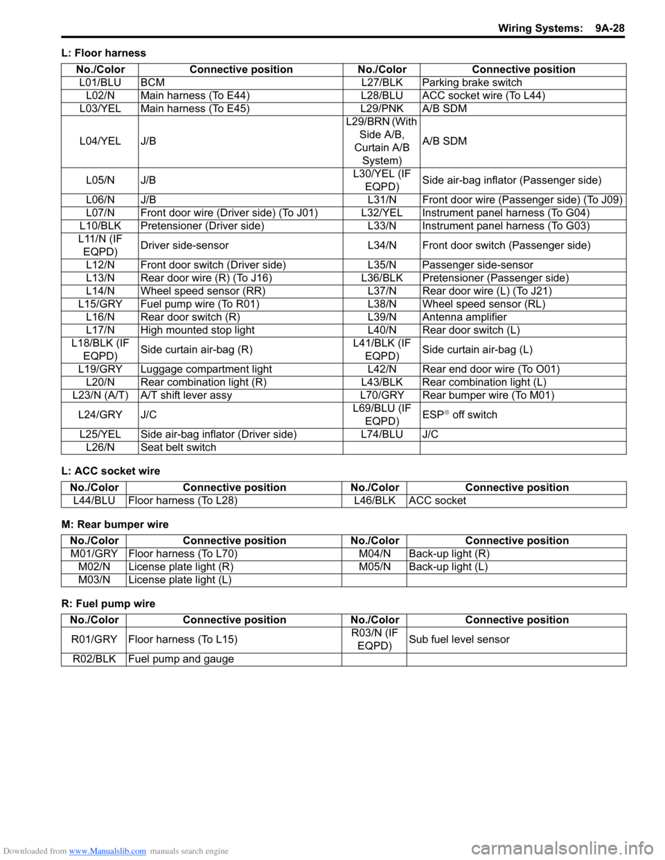
L: Floor harness
L: ACC socket wire
M: Rear bumper wire
R: Fuel pump wireNo./Color Connective position No./Color Connective position
L01/BLU BCM L27/BLK Parking brake switch L02/N Main harness (To E44) L28/BLU ACC socket wire (To L44)
L03/YEL Main harness (To E45) L29/PNK A/B SDM
L04/YEL J/B L29/BRN (With
Side A/B,
Curtain A/B System) A/B SDM
L05/N J/B L30/YEL (IF
EQPD) Side air-bag inflator (Passenger side)
L06/N J/B L31/N Front door wire (Passenger side) (To J09)
L07/N Front door wire (Driver side) (To J01) L32/YEL Instrument panel harness (To G04)
L10/BLK Pretensioner (Driver side) L33/N Instrument panel harness (To G03)
L11/N (IF EQPD) Driver side-sensor L34/N Front door switch (Passenger side)
L12/N Front door switch (Driver side) L35/N Passenger side-sensor
L13/N Rear door wire (R) (To J16) L 36/BLK Pretensioner (Passenger side)
L14/N Wheel speed sensor (RR) L37/N Rear door wire (L) (To J21)
L15/GRY Fuel pump wire (To R01) L38/N Wheel speed sensor (RL)
L16/N Rear door switch (R) L39/N Antenna amplifier
L17/N High mounted stop light L40/N Rear door switch (L)
L18/BLK (IF EQPD) Side curtain air-bag (R) L41/BLK (IF
EQPD) Side curtain air-bag (L)
L19/GRY Luggage compartment light L42/N Rear end door wire (To O01) L20/N Rear combination light (R) L43/BLK Rear combination light (L)
L23/N (A/T) A/T shift lever assy L70/GRY Rear bumper wire (To M01)
L24/GRY J/C L69/BLU (IF
EQPD) ESP
® off switch
L25/YEL Side air-bag inflator (Driver side) L74/BLU J/C L26/N Seat belt switch
No./Color Connective position No./Color Connective position
L44/BLU Floor harness (To L28) L46/BLK ACC socket
No./ColorConnective position No./Color Connective position
M01/GRY Floor harness (To L70) M04/N Back-up light (R)
M02/N License plate light (R) M05/N Back-up light (L)
M03/N License plate light (L)
No./Color Connective position No./Color Connective position
R01/GRY Floor harness (To L15) R03/N (IF
EQPD) Sub fuel level sensor
R02/BLK Fuel pump and gauge