Page 1224 of 1496
Downloaded from www.Manualslib.com manuals search engine 9A-53 Wiring Systems:
J/C
E43
J/C
G16
DLC
G20
G375
E469
E38
G3614
C36 E2415
BLK/ORN
BLK/ORN
BLK/ORN
4
BLK
11
J/C
G15
5
4
516
WHT/RED
C37
GRN/YELGRN/WHT
5 6
YG
BRN
B
P/S
Cont.M
4
"F-3"
25
A
A D
E
AA
PPL/WHT
PPL/WHT
PPL/WHT
PPL/WHT
YEL/GRNWHT/RED
BLK
9
A
PPL
E42
PPLJ/C
ECM
E394
J/B15A RADIO
40
E23
E23
YEL/BLKYEL/REDRED/BLU
13
282620
BLK
2C37
M/T
A/T
48
W
WHT
30
GYGW
BRN/WHTBLU/YEL
28
8
BWBY
IG COIL
#1 Generator
IG COIL
#2
(CAN) "A-3""A-2"
Audio
"G-1"
GRN/WHT
P
7
BCM
Starting motor relay
"A-1"
Transaxle
range sensor
YG"A-1"
ICM
"A-7"
P/S
Cont.M
"F-3"YBYRRBGW"D-7"
Brake light switch
"A-1"Starting motor
PW
PW
G335
WHT/BLKRED/BLK
RBWB
"A-8"
14
6
BCM
A
J/C
E43
APPL
P
E42C
IF EQPD IF EQPD
IF EQPD
I6RS0C910913-03
Page 1226 of 1496
Downloaded from www.Manualslib.com manuals search engine 9A-55 Wiring Systems:
A-6 A/T Control System Circuit DiagramS7RS0B910E007
GRN/YEL
Brakelight
switch
E47
GRN/YEL
C3520 8 7 19 18
9
85 3 6 2
GRN/YEL
Back-up light
20
RED
"D-8"
R
Transaxle
range sensor
TCM
L23
4
3 position switch
A/T
shift lock solenoid
A/T shift
lever assy
BLK/ORN
16
OFF ON
RED
1
RED
BLK
PNK/BLK
GRN/ORNLT GRN/BLK
C28
P
R ND 2L
PNK/BLK
1
2
E24 C36
17
PNK/BLK
BLK
63
BLK/ORN
18
BLK
14
L24
J/C
E45
L024
J/C
E43
J/C (CAN)
G16
BCM
DLC
G207
G375
E469
4
BLK
BLKBLK
11
J/C
G15
3
G36
E3814
E24
C3615
BLK/ORNBLK/ORN
5
23
GRN
RED/BLK
7
E24
C3619
E4114
RED/BLK
PNK
15A
STOP
LAMP8
GRN/WHT
GW
"D-7"
Brake light
3
4
J/B
L018
1
24
10ABACK
A
A
B
B A
A
PPL/WHT
PPL/WHT
PPL/WHT
PPL/WHT
A
A
D
E
LT GRN
P
"A-5"
VSS
PPL
25
R
C36E245
Lg
GY
PB
PW
9
A
Individual circuit
fuse box (No.1)
WHT/BLKRED/BLK
RBWB
BCM
"A-8"
14
6
BLK/ORN
15ARADIO40
G335
WHT/RED
B
B
J/C
G17
WHT/RED
16
J/C
E42
IF EQPD
E24 C36
I7RS0B910915-01
Page 1246 of 1496
Downloaded from www.Manualslib.com manuals search engine 9A-75 Wiring Systems:
C-3 Combination Meter Circuit Diagram (Warning Light)S7RS0B910E021
J/BMETER
10A25
G2831
3
E24
C3615
G36 E3814
Stepper motor and
LED output driver
Voltage regulator
Interface circuit
Micro controllerEPS
G336
RED/BLK
145293025
PNK/BLKGRY
GRY
RED/BLU
PNK/BLK
BLK/ORN
BLK/ORN
BLK/ORN
RED/BLU
P/S
Cont M
"F-3"
RBPBYBYR
YEL/BLKYEL/RED
A/B
SDM
"F-1""A-5"
ABS
Cont.M
"F-2"
G
CAN
High Low
WHTWHTRED
WHTRED
RED
RW
109 8
6L0114
RED/BLKBRN/YEL
L271
Parking
brake
switch
1
2
A
A
16
BLK/ORN
BLK/ORN
J/C
L24
Seat belt
switch
Oil
pressure switch
E24
C3614
BLU
BLU
1C18
D01
RED/BLK
E021
Brake
fluid
level
switch
and
fuel gauge
2
53
BLK
11 5E46G372
4
RW
W
21WHTRED
"A-5"
1
2
RBBBYRB
7
BCM
ECM"B-9"
KLS
ECM
7
R"B-9"
KLS
ECM
Without seat heater
AWith seat heater
BM13A engine, M15A engine
CM16A engine
D
C
C
C
D
(CAN)
(CAN) (CAN)
(CAN)
L26
L61AB
B
BA
A
J/C
G59
BLU
BLU
D
C18
D022G35 E371419
D
I7RS0B910925-01
Page 1256 of 1496
Downloaded from www.Manualslib.com manuals search engine 9A-85 Wiring Systems:
D-7 Brake Light System Circuit DiagramS7RS0B910E028
Brakelight
switch
(R)
Brake light
PNK
BLK
(L)
15A
8STOP
LAMP
E47
L43
GRN/WHT
GRN/WHT
GRN/WHT
5
4
1
L0628
E411
J/B
"F-2"
ABS
Cont.M
GRN/WHT
2
"A-5"
ECM
13
GW
GWGW
TCM
PB
PNK/BLK
"A-6"
GRN/YEL
A/T shift
lever
GY
"A-6"
2 3
A/T
18
Individual circuit
fuse box (No.1)
B
BL74
J/C
L202
5L172
1
High mounted stop light
14
BLK
BLK
2
B
GRN/WHTGRN/WHT
I7RS0B910929-01
Page 1266 of 1496
Downloaded from www.Manualslib.com manuals search engine 9A-95 Wiring Systems:
F-2 Anti-Lock Brake System Circuit DiagramS7RS0B910E035
1326
14
1 3
23
17
E03
ABS
Cont.M
BCM
BLK
30A
ABS
SOL16
30A
ABS
MOT9
WHT/REDWHT/BLU
GRN/WHT
6
BLKREDWHT
PNK/BLK
PB
PNK/BLK
RB
RED/BLU
RED/BLU
149G35 E37
"C-3""A-8"
ECM
"A-5"
J/B10A ABS
31
E419
GRN/ORN
7
GW"D-7"Brake light switch
(CAN)
(CAN)
(ABS)
GRN/WHT
J/B
E411
8
Individual circuit fuse box (No.1)
108
12
RED
R
6
WHT
W
RW
M13A engine, M15A engine
M16A engineA
AB
B
I7RS0B910933-01
Page 1286 of 1496

Downloaded from www.Manualslib.com manuals search engine 9B-4 Lighting Systems:
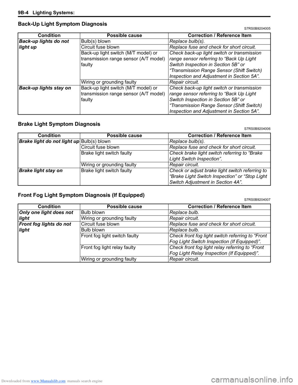
Back-Up Light Symptom DiagnosisS7RS0B9204005
Brake Light Symptom DiagnosisS7RS0B9204006
Front Fog Light Symptom Diagnosis (If Equipped)S7RS0B9204007
ConditionPossible cause Correction / Reference Item
Back-up lights do not
light up Bulb(s) blown
Replace bulb(s).
Circuit fuse blown Replace fuse and check for short circuit.
Back-up light switch (M/T model) or
transmission range sensor (A/T model)
faulty Check back-up light switch or transmission
range sensor referring to “Back Up Light
Switch Inspection in Section 5B” or
“Transmission Range Sensor (Shift Switch)
Inspection and Adjustment in Section 5A”.
Wiring or grounding faulty Repair circuit.
Back-up lights stay on Back-up light switch (M/T model) or
transmission range sensor (A/T model)
faulty Check back-up light switch or transmission
range sensor referring to “Back Up Light
Switch Inspection in Section 5B” or
“Transmission Range Sensor (Shift Switch)
Inspection and Adjustment in Section 5A”.
Condition
Possible cause Correction / Reference Item
Brake light do not light up Bulb(s) blown Replace bulb(s).
Circuit fuse blown Replace fuse and check for short circuit.
Brake light switch faulty Check brake light switch referring to “Brake
Light Switch Inspection”.
Wiring or grounding faulty Repair circuit.
Brake light stay on Brake light switch faulty Check or adjust brake light switch referring to
“Brake Light Switch Inspection” or “Stop Light
Switch Adjustment in Section 4A”.
ConditionPossible cause Correction / Reference Item
Only one light does not
light Bulb blown
Replace bulb.
Wiring or grounding faulty Repair circuit.
Front fog lights do not
light Circuit fuse blown
Replace fuse and check for short circuit.
Bulb blown Replace bulb.
Front fog light switch faulty Check front fog light switch referring to “Front
Fog Light Switch Inspection (If Equipped)”.
Front fog light relay faulty Check front fog light relay referring to “Front
Fog Light Relay Inspection (If Equipped)”.
Wiring or grounding faulty Repair circuit.
Page 1291 of 1496

Downloaded from www.Manualslib.com manuals search engine Lighting Systems: 9B-9
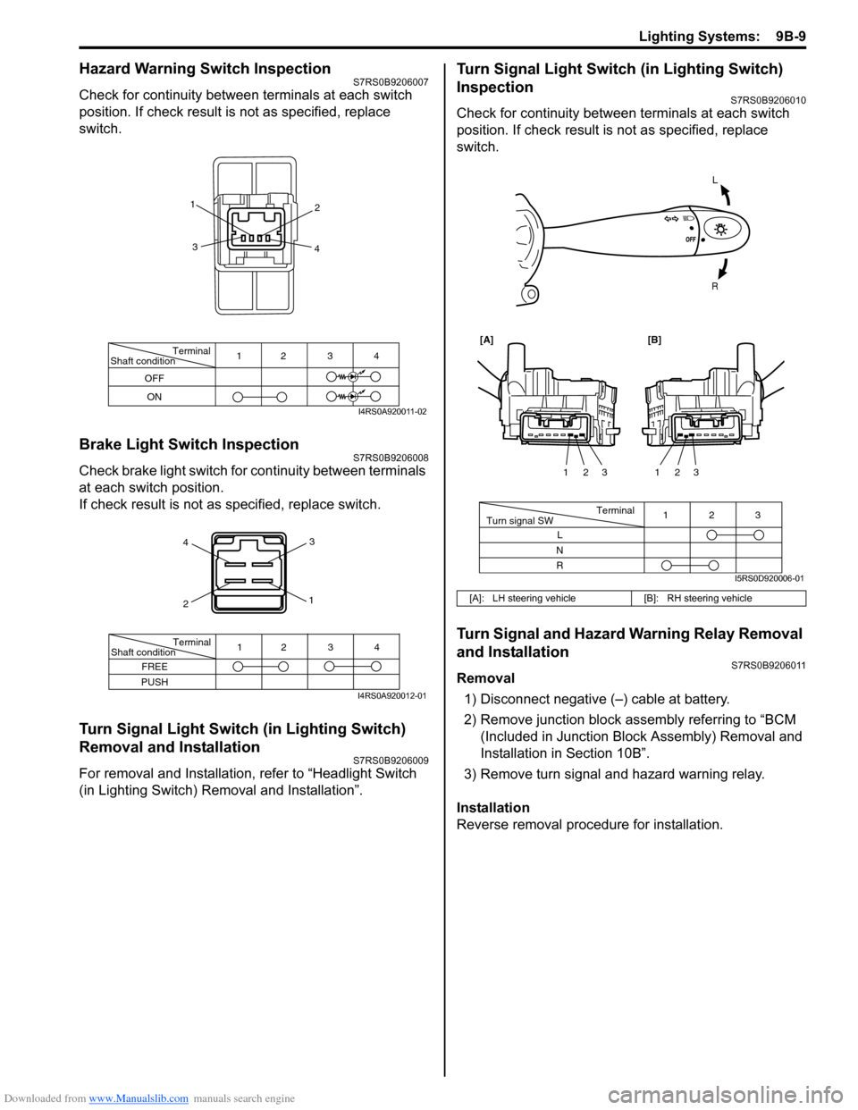
Hazard Warning Switch InspectionS7RS0B9206007
Check for continuity between terminals at each switch
position. If check result is not as specified, replace
switch.
Brake Light Switch InspectionS7RS0B9206008
Check brake light switch for continuity between terminals
at each switch position.
If check result is not as specified, replace switch.
Turn Signal Light Switch (in Lighting Switch)
Removal and Installation
S7RS0B9206009
For removal and Installation, refer to “Headlight Switch
(in Lighting Switch) Removal and Installation”.
Turn Signal Light Switch (in Lighting Switch)
Inspection
S7RS0B9206010
Check for continuity between terminals at each switch
position. If check result is not as specified, replace
switch.
Turn Signal and Hazard Warning Relay Removal
and Installation
S7RS0B9206011
Removal
1) Disconnect negative (–) cable at battery.
2) Remove junction block assembly referring to “BCM (Included in Junction Bl ock Assembly) Removal and
Installation in Section 10B”.
3) Remove turn signal and hazard warning relay.
Installation
Reverse removal procedure for installation.
Terminal
Shaft condition
OFF
ON 12 3 4
1
2
3 4
I4RS0A920011-02
4
2 3
1
Terminal
Shaft condition
FREE
PUSH 12 3 4
I4RS0A920012-01
[A]: LH steering vehicle
[B]: RH steering vehicle
L
R
Terminal
Turn signal SW 3
12
L
N
R 123
123
[A][B]
I5RS0D920006-01
Page 1297 of 1496

Downloaded from www.Manualslib.com manuals search engine Instrumentation / Driver Info. / Horn: 9C-2
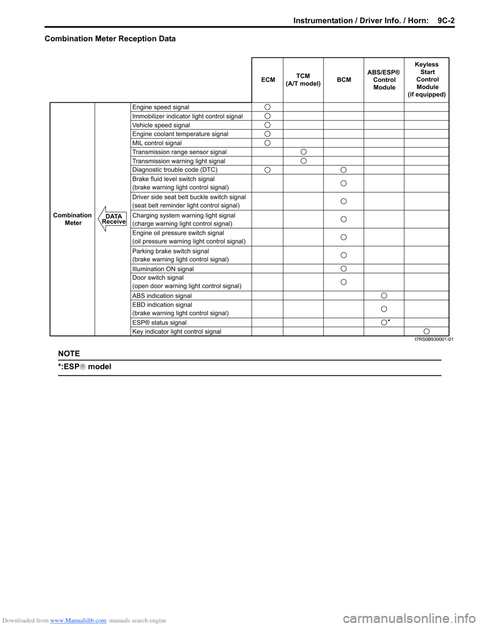
Combination Meter Reception Data
NOTE
*:ESP® model
ECM BCM
Keyless
Start
Control Module
(if equipped)
Combination Meter
TCM
(A/T model)
Engine speed signal
Immobilizer indicator light control signal
Vehicle speed signal
Engine coolant temperature signal
MIL control signal
Transmission range sensor signal
Transmission warning light signal
Diagnostic trouble code (DTC)
Brake fluid level switch signal
(brake warning light control signal)
Driver side seat belt buckle switch signal
(seat belt reminder light control signal)
Charging system warning light signal
(charge warning light control signal)
Engine oil pressure switch signal
(oil pressure warning light control signal)
Parking brake switch signal
(brake warning light control signal)
Illumination ON signal
Door switch signal
(open door warning light control signal)
ABS indication signal
EBD indication signal
(brake warning light control signal)
Key indicator light control signal ABS/ESP®
ControlModule
DATA
Receive
*
ESP® status signal
I7RS0B930001-01