2005 SUZUKI SWIFT ECU
[x] Cancel search: ECUPage 828 of 1496

Downloaded from www.Manualslib.com manuals search engine 5B-14 Manual Transmission/Transaxle:
Fifth Gear Disassembly and AssemblyS7RS0B5206014
Disassembly1) Remove cover bolts and take off transaxle side cover (1).
CAUTION!
Care should be taken not to distort side cover
when it is removed from left case.
2) Using snap ring pliers, remove circlip (1).
3) Remove 5th shift fork bolt (2).
4) Remove gear shift fork (3), synchronizer sleeve &
hub assembly (4), synchron izer levers, synchronizer
ring and input shaft 5th gear (5) all together. Use
gear puller for removal if spline fitting of hub is tight. 5) Unfasten caulking of countershaft nut (2), install
input shaft 5th gear (1) and special tool to stop
rotation of shafts, and then remove countershaft nut
(2).
Special tool
(A): 09927–76060
6) Remove input shaft 5th gear, needle bearing and then countershaft 5th gear (1). Gear puller (2) would
be necessary if spline fitting of countershaft 5th gear
is tight.
11. Sensor cap 34. Washer
12. Oil gutter bolt : Apply thread lock 99000-32110 to all around thread part of bolt. 35. Side bearing retainer
13. Left case plate bolts : Apply thread lock 99000-32110 to all around thread part of bolt. 36. O-ring
14. Sensor cap bolt 37. Oil seal
: Apply grease 99000-25011 to oil seal lip.
15. Side cover bolts 38. Outer race
16. Transaxle case bolts 39. Breather hose
17. 5th speed synchronizer ring 40. Side bearing retainer bolt
18. 5th speed synchronizer lever : 23 N⋅m (2.3 kgf-m, 17.0 lb-ft)
19. 5th speed synchronizer sleeve & hub : 21 N⋅m (2.1 kgf-m, 15.5 lb-ft)
20. Circlip :10 N⋅m (1.0 kgf-m, 7.5 lb-ft)
21. Bearing set shim : 100 N⋅m (10.0 kgf-m, 72.5 lb-ft)
22. Countershaft 5th gear : Do not reuse.
23. Countershaft nut : After tightening nut to specified torque, caulk nut securely. : Apply transaxle oil.
I4RS0A520027-01
342
1
5
I4RS0A520028-01
1(A)
2
I3RM0B521014-01
I4RS0A520041-01
Page 829 of 1496

Downloaded from www.Manualslib.com manuals search engine Manual Transmission/Transaxle: 5B-15
Assembly1) Assemble 5th speed synchronizer sleeve (1), hub (2), 5th speed synchronizer levers (3) and
synchronizer ring (4) as follows.
a) Install hub (1) to 5th speed synchronizer sleeves (2) in specified direction as shown in figure.
b) Fit 5th speed synchronizer levers (1) to hub (2) as shown in figure.
NOTE
Align protrusion A of 5th speed synchronizer
levers (1) with groove of hub (2).
c) Install synchronizer ring (1) to hub (2) as shown in figure.
2) Install 5th gear (1) to countershaft facing machined boss A inward.
3) Install needle bearing to input shaft, apply oil then install input shaft 5th gear (1) and special tool to stop
shaft rotation.
Special tool
(A): 09927–76060
4) Tighten new countershaft nut (2) to specified torque, and caulk countershaft nut securely.
Tightening torque
Countershaft nut (a): 100 N·m (10.0 kgf-m, 72.5
lb-ft)
A: Chamfered side B: Long boss
I4RH01520054-01
1
2
B
A
I4RH01520048-01
1A
2
A
I4RH01520049-01
A: Machined boss (Inside)
B: No machining (Outside)
1
2
I4RH01520055-01
I2RH01520088-01
1
(A)
2, (a)
I3RM0B521016-01
Page 841 of 1496
Downloaded from www.Manualslib.com manuals search engine Manual Transmission/Transaxle: 5B-27
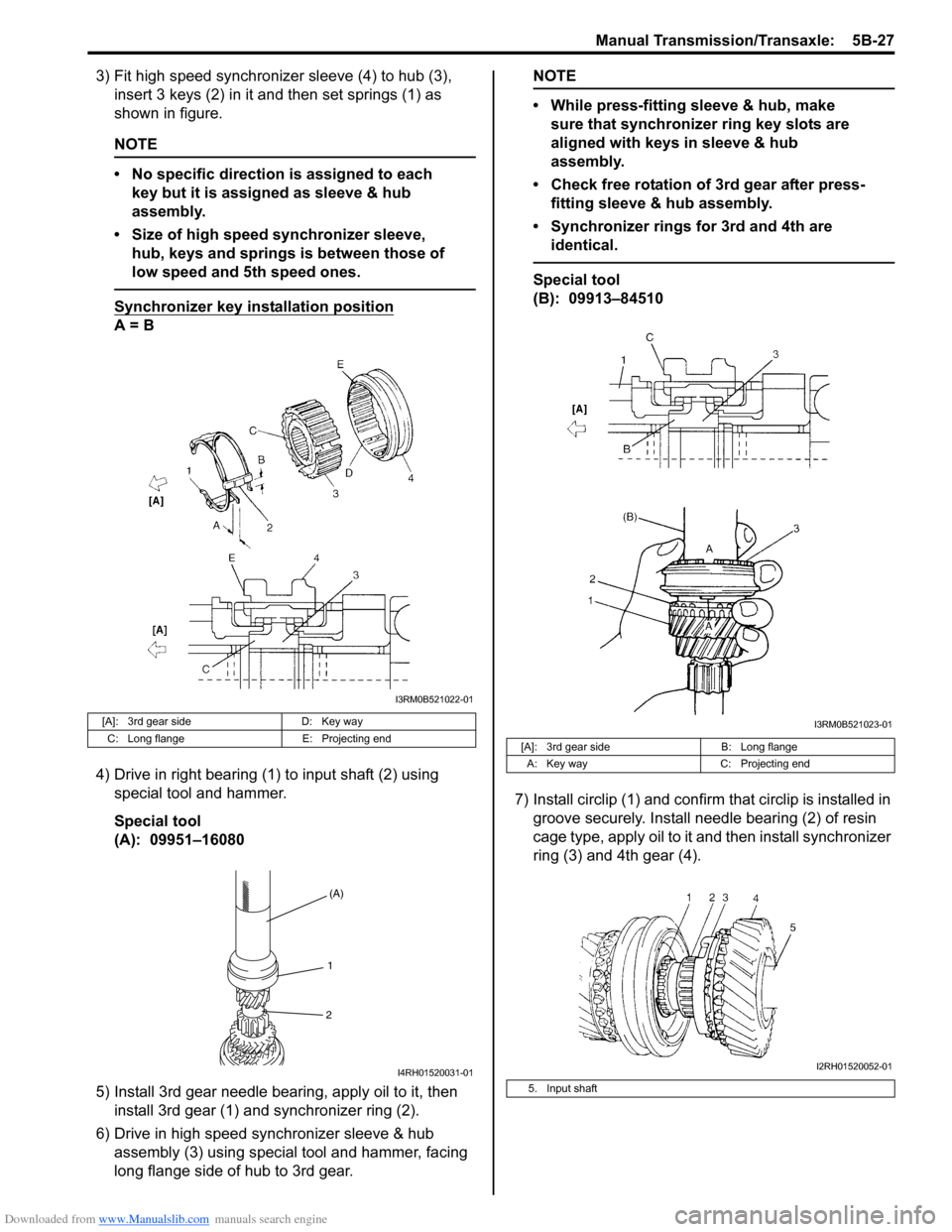
3) Fit high speed synchronizer sleeve (4) to hub (3), insert 3 keys (2) in it and then set springs (1) as
shown in figure.
NOTE
• No specific direction is assigned to each key but it is assigned as sleeve & hub
assembly.
• Size of high speed synchronizer sleeve, hub, keys and springs is between those of
low speed and 5th speed ones.
Synchronizer key in stallation position
A = B
4) Drive in right bearing (1) to input shaft (2) using special tool and hammer.
Special tool
(A): 09951–16080
5) Install 3rd gear needle bearing, apply oil to it, then install 3rd gear (1) and synchronizer ring (2).
6) Drive in high speed synchronizer sleeve & hub assembly (3) using special tool and hammer, facing
long flange side of hub to 3rd gear.
NOTE
• While press-fitting sleeve & hub, make sure that synchronizer ring key slots are
aligned with keys in sleeve & hub
assembly.
• Check free rotation of 3rd gear after press- fitting sleeve & hub assembly.
• Synchronizer rings for 3rd and 4th are identical.
Special tool
(B): 09913–84510
7) Install circlip (1) and confirm that circlip is installed in
groove securely. Install needle bearing (2) of resin
cage type, apply oil to it and then install synchronizer
ring (3) and 4th gear (4).
[A]: 3rd gear side D: Key way
C: Long flange E: Projecting end
I3RM0B521022-01
(A)
1
2
I4RH01520031-01
[A]: 3rd gear side B: Long flange
A: Key way C: Projecting end
5. Input shaft
I3RM0B521023-01
I2RH01520052-01
Page 844 of 1496
Downloaded from www.Manualslib.com manuals search engine 5B-30 Manual Transmission/Transaxle:
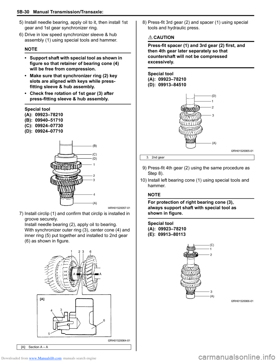
5) Install needle bearing, apply oil to it, then install 1st gear and 1st gear synchronizer ring.
6) Drive in low speed synchronizer sleeve & hub assembly (1) using special tools and hammer.
NOTE
• Support shaft with special tool as shown in figure so that retainer of bearing cone (4)
will be free from compression.
• Make sure that synchronizer ring (2) key slots are aligned with keys while press-
fitting sleeve & hub assembly.
• Check free rotation of 1st gear (3) after press-fitting sleeve & hub assembly.
Special tool
(A): 09923–78210
(B): 09940–51710
(C): 09924–07730
(D): 09924–07710
7) Install circlip (1) and confirm that circlip is installed in groove securely.
Install needle bearing (2), apply oil to bearing.
With synchronizer outer ring (3), center cone (4) and
inner ring (5) put together and installed to 2nd gear
(6) as shown in figure. 8) Press-fit 3rd gear (2) and spacer (1) using special
tools and hydraulic press.
CAUTION!
Press-fit spacer (1) and 3rd gear (2) first, and
then 4th gear later separately so that
countershaft will not be compressed
excessively.
Special tool
(A): 09923–78210
(D): 09913–84510
9) Press-fit 4th gear (2) using the same procedure as Step 8).
10) Install left bearing cone (1) using special tools and hammer.
NOTE
For protection of right bearing cone (3),
always support shaft with special tool as
shown in figure.
Special tool
(A): 09923–78210
(E): 09913–80113
[A]: Section A – A
I4RH01520057-01
I2RH01520064-01
3. 2nd gear
I2RH01520065-01
I2RH01520066-01
Page 853 of 1496

Downloaded from www.Manualslib.com manuals search engine Clutch: 5C-1
Transmission / Transaxle
Clutch
General Description
Clutch ConstructionS7RS0B5301001
The clutch is a diaphragm spring clutch of a dry single disc type. The diaphragm spring is of a tapering-finger type,
which is a solid ring in the outer diameter part, with a series of tapered fingers pointing inward.
The disc, carrying four torsional coil springs, is positione d on the transaxle input shaft with an involute spline fit.
The clutch cover is secured to the flywheel, and carries the diaphragm spring in such a way that the peripheral edge
part of the spring pushes on the pressure plate against the flywheel (with the disc in between), when the clutch release
bearing is held back. This is the engaged condition of the clutch.
Depressing the clutch pedal c auses the release bearing to advance and pushes on the tips of the tapered fingers of
the diaphragm spring. When this happens, the diaphragm sp ring pulls the pressure plate away from the flywheel,
thereby interrupting the flow of drive from flywheel through clutch disc to transaxle input shaft. Clutch fluid is supplied
from brake fluid reservoir. Clutch fluid level can be checked by brake fluid level of brake fluid reservoir.
[A]: For petrol engine model2. Flywheel5. Clutch cover 8. Input shaft bearing
[B]: For diesel engine model 3. Clutch disc6. Diaphragm spring 9. Input shaft
1. Crankshaft 4. Pressure plate7. Release bearing 10. Release shaft
I4RS0A530001-01
Page 856 of 1496
Downloaded from www.Manualslib.com manuals search engine 5C-4 Clutch:
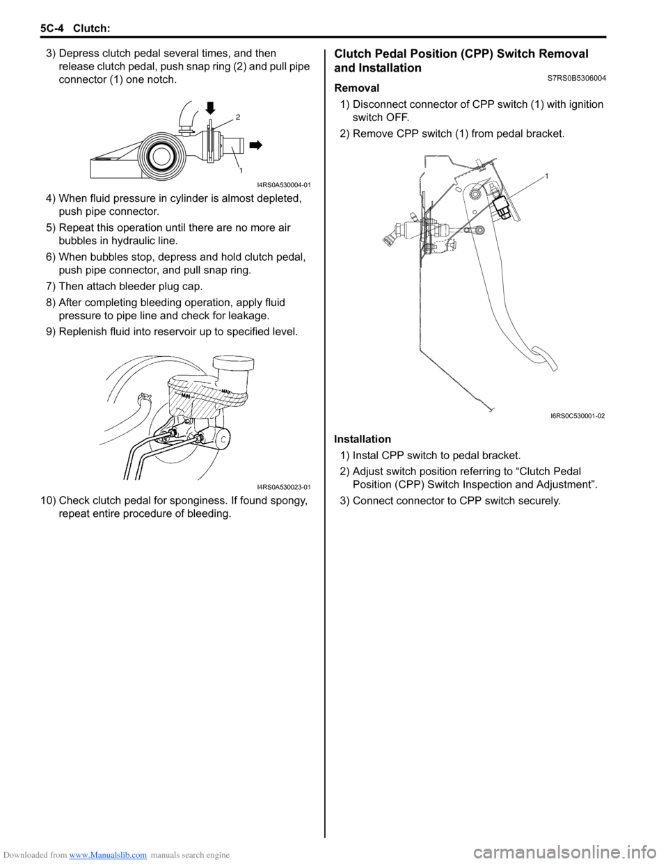
3) Depress clutch pedal several times, and then release clutch pedal, push snap ring (2) and pull pipe
connector (1) one notch.
4) When fluid pressure in cylinder is almost depleted, push pipe connector.
5) Repeat this operation until there are no more air bubbles in hydraulic line.
6) When bubbles stop, depress and hold clutch pedal, push pipe connector, and pull snap ring.
7) Then attach bleeder plug cap.
8) After completing bleeding operation, apply fluid pressure to pipe line and check for leakage.
9) Replenish fluid into reserv oir up to specified level.
10) Check clutch pedal for sponginess. If found spongy, repeat entire procedure of bleeding.Clutch Pedal Position (CPP) Switch Removal
and Installation
S7RS0B5306004
Removal
1) Disconnect connector of C PP switch (1) with ignition
switch OFF.
2) Remove CPP switch (1 ) from pedal bracket.
Installation 1) Instal CPP switch to pedal bracket.
2) Adjust switch position re ferring to “Clutch Pedal
Position (CPP) Switch Inspection and Adjustment”.
3) Connect connector to CPP switch securely.
2
1
I4RS0A530004-01
I4RS0A530023-01
1
I6RS0C530001-02
Page 858 of 1496
Downloaded from www.Manualslib.com manuals search engine 5C-6 Clutch:
Clutch Fluid Pipe Removal and InstallationS7RS0B5306007
Removal
CAUTION!
Do not allow fluid to get on painted surface. It
may cause painted surface damage.
1) Remove dust and dirt from each joint of pipe to be disconnected and clean around brake master
cylinder reservoir cap.
2) Take out fluid with syringe or such from brake master cylinder reservoir.
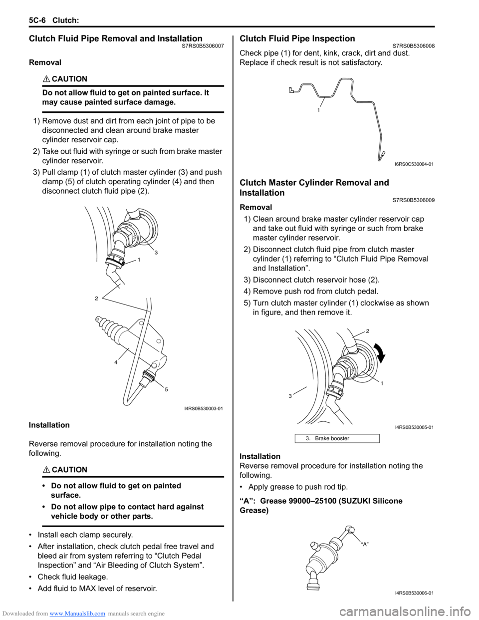
3) Pull clamp (1) of clutch master cylinder (3) and push clamp (5) of clutch operating cylinder (4) and then
disconnect clutch fluid pipe (2).
Installation
Reverse removal procedure for installation noting the
following.
CAUTION!
• Do not allow fluid to get on painted surface.
• Do not allow pipe to contact hard against vehicle body or other parts.
• Install each clamp securely.
• After installation, check clutch pedal free travel and bleed air from system referring to “Clutch Pedal
Inspection” and “Air Blee ding of Clutch System”.
• Check fluid leakage.
• Add fluid to MAX level of reservoir.
Clutch Fluid Pipe InspectionS7RS0B5306008
Check pipe (1) for dent, kink, crack, dirt and dust.
Replace if check result is not satisfactory.
Clutch Master Cylinder Removal and
Installation
S7RS0B5306009
Removal 1) Clean around brake master cylinder reservoir cap and take out fluid with syringe or such from brake
master cylinder reservoir.
2) Disconnect clutch fluid pipe from clutch master cylinder (1) referring to “C lutch Fluid Pipe Removal
and Installation”.
3) Disconnect clutch reservoir hose (2).
4) Remove push rod from clutch pedal.
5) Turn clutch master cylinder (1) clockwise as shown in figure, and then remove it.
Installation
Reverse removal procedure for installation noting the
following.
• Apply grease to push rod tip.
“A”: Grease 99000–25100 (SUZUKI Silicone
Grease)
31
2
5
4
I4RS0B530003-01
3. Brake booster
1
I6RS0C530004-01
1
2
3
I4RS0B530005-01
“A”
I4RS0B530006-01
Page 873 of 1496
Downloaded from www.Manualslib.com manuals search engine Steering Wheel and Column: 6B-2
Diagnostic Information and Procedures
Checking Steering Column for Accident
Damage
S7RS0B6204001
NOTE
Vehicles involved in accidents resulting in
body damage, where steering column has
been impacted or air bag deployed may have
a damaged or misaligned steering column.
Checking Procedure
NOTE
The steering column used in each vehicle is
one of the two types as shown.
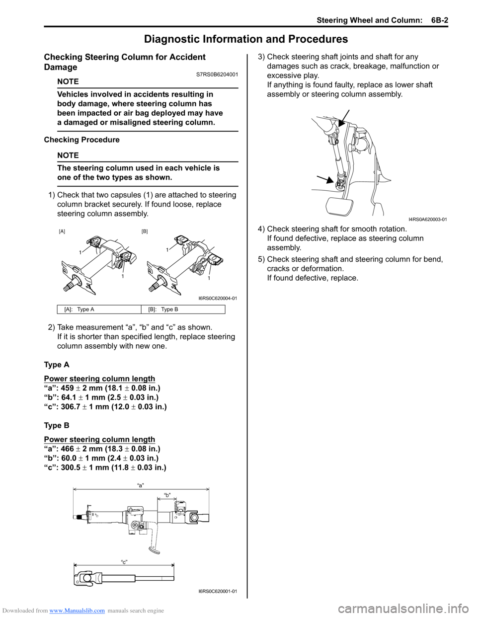
1) Check that two capsules (1) are attached to steering column bracket securely. If found loose, replace
steering column assembly.
2) Take measurement “a”, “b” and “c” as shown. If it is shorter than spec ified length, replace steering
column assembly with new one.
Ty p e A
Power steering column length
“a”: 459 ± 2 mm (18.1 ± 0.08 in.)
“b”: 64.1 ± 1 mm (2.5 ± 0.03 in.)
“c”: 306.7 ± 1 mm (12.0 ± 0.03 in.)
Ty p e B
Power steering column length
“a”: 466 ± 2 mm (18.3 ± 0.08 in.)
“b”: 60.0 ± 1 mm (2.4 ± 0.03 in.)
“c”: 300.5 ± 1 mm (11.8 ± 0.03 in.) 3) Check steering shaft joints and shaft for any
damages such as crack, breakage, malfunction or
excessive play.
If anything is found faulty, replace as lower shaft
assembly or steering column assembly.
4) Check steering shaft for smooth rotation. If found defective, replace as steering column
assembly.
5) Check steering shaft and steering column for bend, cracks or deformation.
If found defective, replace.
[A]: Type A [B]: Type B
[A] [B]
1
1
1
1
I6RS0C620004-01
I6RS0C620001-01
I4RS0A620003-01