2005 SUZUKI SWIFT Air bag diagnostic
[x] Cancel search: Air bag diagnosticPage 1138 of 1496
Downloaded from www.Manualslib.com manuals search engine 8B-100 Air Bag System:
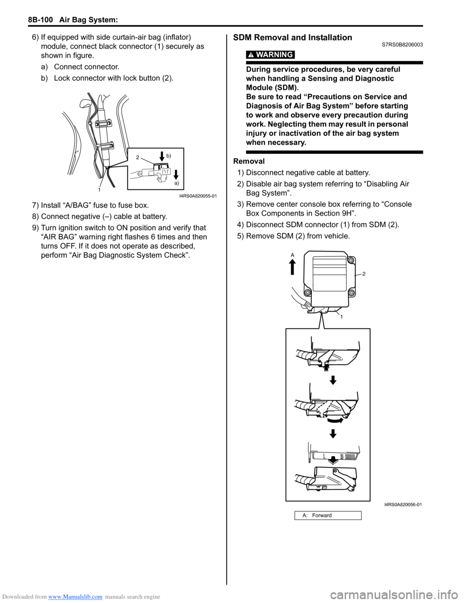
6) If equipped with side curtain-air bag (inflator) module, connect black connector (1) securely as
shown in figure.
a) Connect connector.
b) Lock connector with lock button (2).
7) Install “A/BAG” fuse to fuse box.
8) Connect negative (–) cable at battery.
9) Turn ignition switch to ON position and verify that “AIR BAG” warning right flashes 6 times and then
turns OFF. If it does not operate as described,
perform “Air Bag Diagn ostic System Check”.SDM Removal and InstallationS7RS0B8206003
WARNING!
During service procedures, be very careful
when handling a Sensing and Diagnostic
Module (SDM).
Be sure to read “Precautions on Service and
Diagnosis of Air Bag System” before starting
to work and observe every precaution during
work. Neglecting them ma y result in personal
injury or inactivation of the air bag system
when necessary.
Removal
1) Disconnect negative cable at battery.
2) Disable air bag system referring to “Disabling Air Bag System”.
3) Remove center console box referring to “Console Box Components in Section 9H”.
4) Disconnect SDM connector (1) from SDM (2).
5) Remove SDM (2) from vehicle.
1
2
a)
b)
I4RS0A820055-01
A: Forward
2
1
A
I4RS0A820056-01
Page 1139 of 1496
Downloaded from www.Manualslib.com manuals search engine Air Bag System: 8B-101
Installation1) Check that none of the following faulty conditions exists.
• Bend, scratch, deformity in vehicle body where SDM is mounted.
• Foreign matter or rust on mating surface of vehicle body where SDM is mounted.
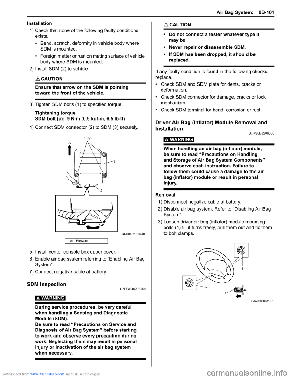
2) Install SDM (2) to vehicle.
CAUTION!
Ensure that arrow on the SDM is pointing
toward the front of the vehicle.
3) Tighten SDM bolts (1) to specified torque.
Tightening torque
SDM bolt (a): 9 N·m (0.9 kgf-m, 6.5 lb-ft)
4) Connect SDM connector (2) to SDM (3) securely.
5) Install center console box upper cover.
6) Enable air bag system referring to “Enabling Air Bag System”.
7) Connect negative cable at battery.
SDM InspectionS7RS0B8206004
WARNING!
During service procedures, be very careful
when handling a Sensing and Diagnostic
Module (SDM).
Be sure to read “Precautions on Service and
Diagnosis of Air Bag System” before starting
to work and observe every precaution during
work. Neglecting them ma y result in personal
injury or inactivation of the air bag system
when necessary.
CAUTION!
• Do not connect a tester whatever type it may be.
• Never repair or disassemble SDM.
• If SDM has been dropped, it should be replaced.
If any faulty condition is fo und in the following checks,
replace.
• Check SDM and SDM plate for dents, cracks or deformation.
• Check SDM connector for damage, cracks or lock mechanism.
• Check SDM terminal for bend, corrosion or rust.
Driver Air Bag (Inflator) Module Removal and
Installation
S7RS0B8206005
WARNING!
When handling an air bag (inflator) module,
be sure to read “Precautions on Handling
and Storage of Air Bag System Components”
and observe each instruction. Failure to
follow them could cause a damage to the air
bag (inflator) module or result in personal
injury.
Removal 1) Disconnect negative cable at battery.
2) Disable air bag system. Re fer to “Disabling Air Bag
System”.
3) Loosen driver air bag (inflator) module mounting bolts (1) till it turns freely, pull them out and fix them
to bolt clamps.
A: Forward
2 3
A
1, (a)
I4RS0A820107-01
I3JA01820031-01
Page 1163 of 1496
Downloaded from www.Manualslib.com manuals search engine Air Bag System: 8B-125
Specifications
Tightening Torque SpecificationsS7RS0B8207001
NOTE
The specified tightening torque is also described in the following.
“Air Bag System Components, Wiring and Connectors Location”
Reference:
For the tightening torque of fastener not specified in this section, refer to “Fasteners Information in Section 0A”.
Special Tools and Equipment
Use of Special ToolsS7RS0B8208001
WARNING!
To avoid deployment when troubleshooting
the air bag system, do not use electrical test
equipment such as a battery powered or AC
powered voltmeter, ohmmeter, etc., or any
type of electrical equipment other than that
specified. Do not use a non-powered probe
type tester.
Instructions must be followed carefully,
otherwise personal injury may result.
You should be familiar with the tools listed under the
heading “Special Tool”. You should be able to measure
voltage and resistance. You should be familiar with
proper use of a scan tool such as Air Bag Driver /
Passenger Load Tool, Connector Test Adapter Kit and
the Digital Multimeter.
Special tool
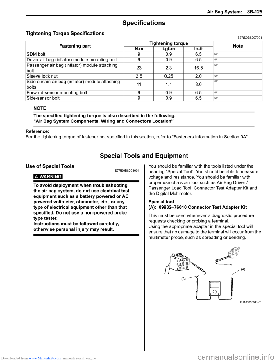
(A): 09932–76010 Connector Test Adapter Kit
This must be used whenever a diagnostic procedure
requests checking or probing a terminal.
Using the appropriate adapter in the special tool will
ensure that no damage to the terminal will occur from the
multimeter probe, such as spreading or bending.
Fastening part
Tightening torque
Note
N ⋅mkgf-mlb-ft
SDM bolt 9 0.9 6.5 �)
Driver air bag (inflator) module mounting bolt 9 0.9 6.5 �)
Passenger air bag (inflator) module attaching
bolt 23 2.3 16.5�)
Sleeve lock nut 2.5 0.25 2.0 �)
Side curtain-air bag (inflator) module attaching
bolts 11 1.1 8.0�)
Forward-sensor mounting bolt 9 0.9 6.5 �)
Side-sensor bolt 9 0.9 6.5 �)
I3JA01820041-01
Page 1164 of 1496
Downloaded from www.Manualslib.com manuals search engine 8B-126 Air Bag System:
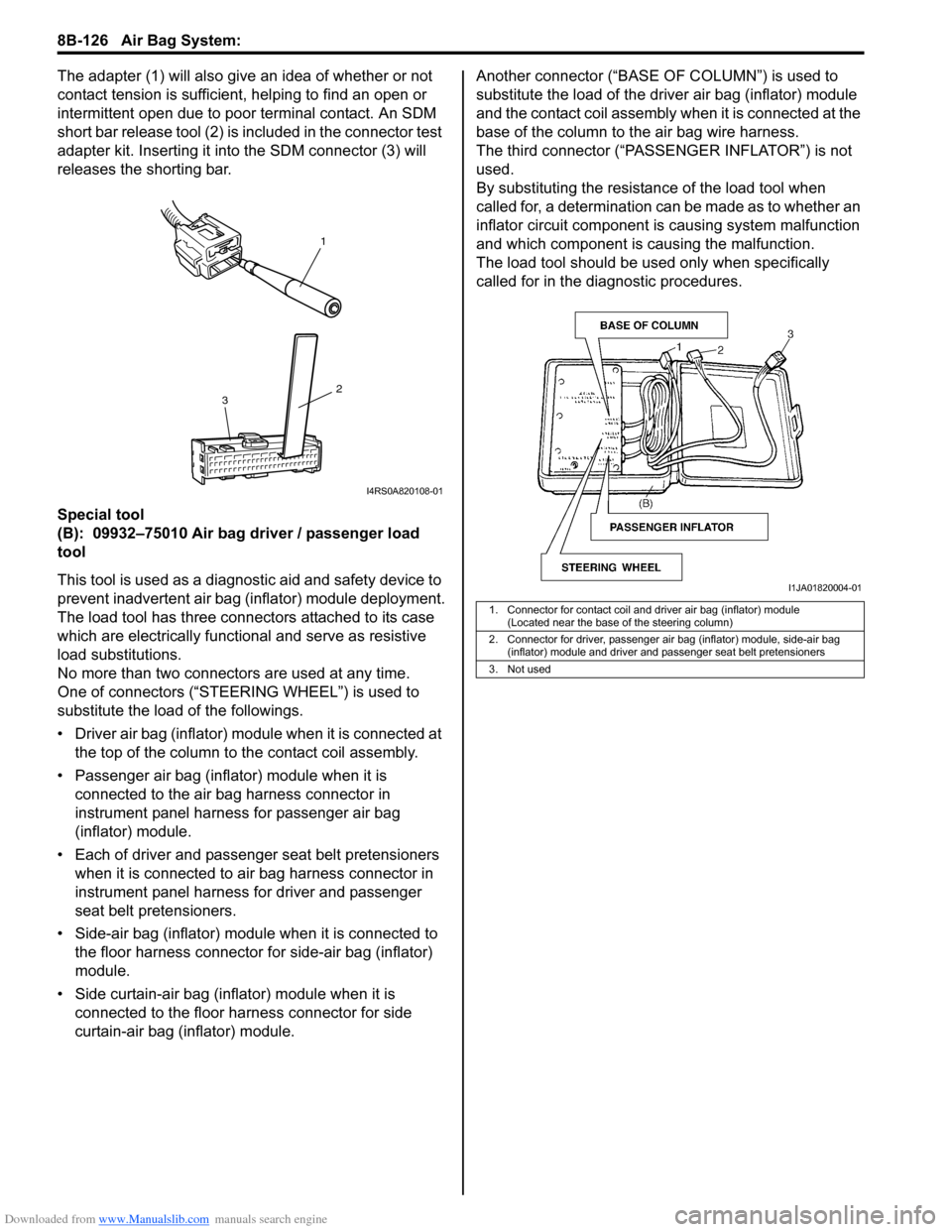
The adapter (1) will also give an idea of whether or not
contact tension is sufficient, helping to find an open or
intermittent open due to poor terminal contact. An SDM
short bar release tool (2) is included in the connector test
adapter kit. Inserting it in to the SDM connector (3) will
releases the shorting bar.
Special tool
(B): 09932–75010 Air bag driver / passenger load
tool
This tool is used as a diagno stic aid and safety device to
prevent inadvertent air bag (inflator) module deployment.
The load tool has three connectors attached to its case
which are electrically functional and serve as resistive
load substitutions.
No more than two connectors are used at any time.
One of connectors (“STEER ING WHEEL”) is used to
substitute the load of the followings.
• Driver air bag (inflator) module when it is connected at the top of the column to the contact coil assembly.
• Passenger air bag (inflator) module when it is connected to the air bag harness connector in
instrument panel harness for passenger air bag
(inflator) module.
• Each of driver and passen ger seat belt pretensioners
when it is connected to air bag harness connector in
instrument panel harness for driver and passenger
seat belt pretensioners.
• Side-air bag (inflator) module when it is connected to the floor harness connector for side-air bag (inflator)
module.
• Side curtain-air bag (inflator) module when it is connected to the floor harness connector for side
curtain-air bag (inflator) module. Another connec
tor (“BASE OF COLUMN ”) is used to
substitute the load of the driver air bag (inflator) module
and the contact coil assembly when it is connected at the
base of the column to the air bag wire harness.
The third connector (“PASSENGER INFLATOR”) is not
used.
By substituting the resistan ce of the load tool when
called for, a determination can be made as to whether an
inflator circuit component is causing system malfunction
and which component is causing the malfunction.
The load tool should be used only when specifically
called for in the diagnostic procedures.
1
2
3
I4RS0A820108-01
1. Connector for contact coil and driver air bag (inflator) module
(Located near the base of the steering column)
2. Connector for driver, passenger air bag (inflator) module, side-air bag (inflator) module and driver and passenger seat belt pretensioners
3. Not used
I1JA01820004-01
Page 1401 of 1496
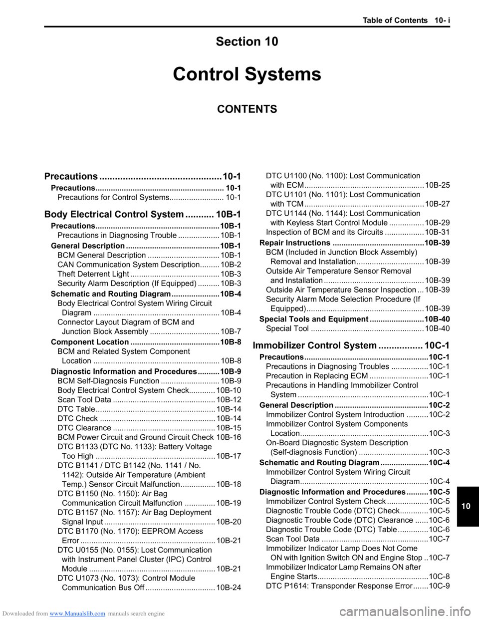
Downloaded from www.Manualslib.com manuals search engine Table of Contents 10- i
10
Section 10
CONTENTS
Control Systems
Precautions ............................................... 10-1
Precautions........................................................... 10-1
Precautions for Control Systems......................... 10-1
Body Electrical Contro l System ........... 10B-1
Precautions......................................................... 10B-1
Precautions in Diagnosing Trouble ................... 10B-1
General Description ........................................... 10B-1 BCM General Description ................................. 10B-1
CAN Communication System Description......... 10B-2
Theft Deterrent Light ......................................... 10B-3
Security Alarm Description (If Equipped) .......... 10B-3
Schematic and Routing Diagram ...................... 10B-4 Body Electrical Control System Wiring Circuit Diagram .......................................................... 10B-4
Connector Layout Diagram of BCM and Junction Block Assembly ................................ 10B-7
Component Locatio n ......................................... 10B-8
BCM and Related System Component Location .......................................................... 10B-8
Diagnostic Information an d Procedures .......... 10B-9
BCM Self-Diagnosis Function ........................... 10B-9
Body Electrical Control System Check............ 10B-10
Scan Tool Data ............................................... 10B-12
DTC Table ....................................................... 10B-14
DTC Check ..................................................... 10B-14
DTC Clearance ............................................... 10B-15
BCM Power Circuit and Ground Circuit Check 10B-16
DTC B1133 (DTC No. 1133): Battery Voltage Too High ....................................................... 10B-17
DTC B1141 / DTC B1142 (No. 1141 / No. 1142): Outside Air Temperature (Ambient
Temp.) Sensor Circuit Ma lfunction ................ 10B-18
DTC B1150 (No. 1150): Air Bag Communication Circuit Malfunction .............. 10B-19
DTC B1157 (No. 1157): Air Bag Deployment Signal Input ................................................... 10B-20
DTC B1170 (No. 1170 ): EEPROM Access
Error .............................................................. 10B-21
DTC U0155 (No. 0155): Lost Communication with Instrument Panel Cluster (IPC) Control
Module .......................................................... 10B-21
DTC U1073 (No. 1073): Control Module Communication Bus Off ................................ 10B-24 DTC U1100 (No. 1100): Lost Communication
with ECM ....................................................... 10B-25
DTC U1101 (No. 1101): Lost Communication with TCM ....................................................... 10B-27
DTC U1144 (No. 1144): Lost Communication with Keyless Start Control Module ................ 10B-29
Inspection of BCM and its Circuits .................. 10B-31
Repair Instructions ........... ...............................10B-39
BCM (Included in Junction Block Assembly) Removal and Installation ............................... 10B-39
Outside Air Temperature Sensor Removal and Installation .............................................. 10B-39
Outside Air Temperature Sensor Inspection ... 10B-39
Security Alarm Mode Selection Procedure (If Equipped) ...................................................... 10B-39
Special Tools and Equipmen t .........................10B-40
Special Tool .................................................... 10B-40
Immobilizer Control Syst em ................. 10C-1
Precautions.........................................................10C-1
Precautions in Diagnosing Troubles .................10C-1
Precaution in Replacing ECM ...........................10C-1
Precautions in Handli ng Immobilizer Control
System ............................................................10C-1
General Description ...........................................10C-2 Immobilizer Control System Introduction ..........10C-2
Immobilizer Control System Components Location...........................................................10C-3
On-Board Diagnostic System Description (Self-diagnosis Function) ................................10C-3
Schematic and Routing Diag ram ......................10C-4
Immobilizer Control System Wiring Circuit Diagram...........................................................10C-4
Diagnostic Information an d Procedures ..........10C-5
Immobilizer Control System Check ...................10C-5
Diagnostic Trouble Code (DTC) Check.............10C-5
Diagnostic Trouble Code (DTC) Clearance ......10C-6
Diagnostic Trouble Code (DTC) Table ..............10C-6
Scan Tool Data .................................................10C-7
Immobilizer Indicator Lamp Does Not Come ON with Ignition Switch ON and Engine Stop ..10C-7
Immobilizer Indicator Lamp Remains ON after Engine Starts...................................................10C-8
DTC P1614: Transponder Re sponse Error .......10C-9