Page 507 of 687
Downloaded from www.Manualslib.com manuals search engine 6A1-26 ENGINE MECHANICAL (M13 ENGINE)
INSTALLATION
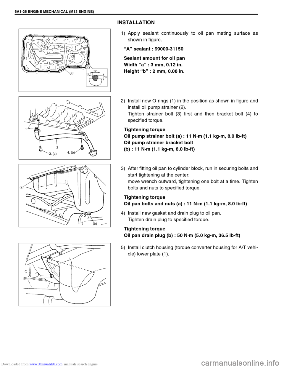
1) Apply sealant continuously to oil pan mating surface as
shown in figure.
“A” sealant : 99000-31150
Sealant amount for oil pan
Width “a” : 3 mm, 0.12 in.
Height “b” : 2 mm, 0.08 in.
2) Install new O-rings (1) in the position as shown in figure and
install oil pump strainer (2).
Tighten strainer bolt (3) first and then bracket bolt (4) to
specified torque.
Tightening torque
Oil pump strainer bolt (a) : 11 N·m (1.1 kg-m, 8.0 lb-ft)
Oil pump strainer bracket bolt
(b) : 11 N·m (1.1 kg-m, 8.0 lb-ft)
3) After fitting oil pan to cylinder block, run in securing bolts and
start tightening at the center:
move wrench outward, tightening one bolt at a time. Tighten
bolts and nuts to specified torque.
Tightening torque
Oil pan bolts and nuts (a) : 11 N·m (1.1 kg-m, 8.0 lb-ft)
4) Install new gasket and drain plug to oil pan.
Tighten drain plug to specified torque.
Tightening torque
Oil pan drain plug (b) : 50 N·m (5.0 kg-m, 36.5 lb-ft)
5) Install clutch housing (torque converter housing for A/T vehi-
cle) lower plate (1).
Page 555 of 687
Downloaded from www.Manualslib.com manuals search engine 6A1-74 ENGINE MECHANICAL (M13 ENGINE)
a) For right hand steering vehicle:
With hose connected, detach A/C compressor from its
bracket.
b) For left hand steering vehicle:
i) Recover refrigerant from refrigeration system using recov-
ery and recycling equipment.
ii) Disconnect magnet clutch lead wire.
iii) Remove suction pipe and disconnect discharge pipe from
A/C compressor.
iv) Remove A/C compressor from its bracket.
When servicing above steps, refer to “Compressor” in Section 1B.
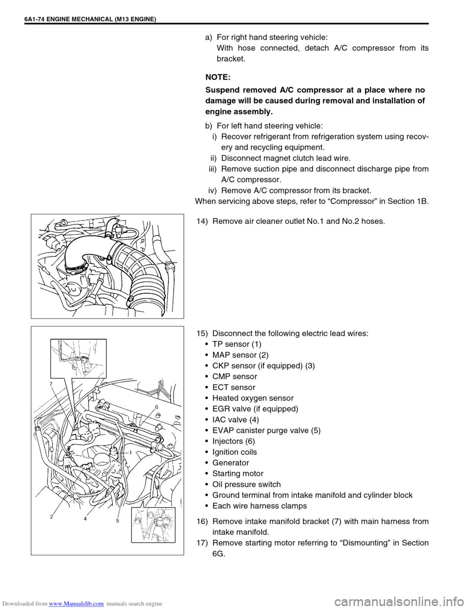
14) Remove air cleaner outlet No.1 and No.2 hoses.
15) Disconnect the following electric lead wires:
TP sensor (1)
MAP sensor (2)
CKP sensor (if equipped) (3)
CMP sensor
ECT sensor
Heated oxygen sensor
EGR valve (if equipped)
IAC valve (4)
EVAP canister purge valve (5)
Injectors (6)
Ignition coils
Generator
Starting motor
Oil pressure switch
Ground terminal from intake manifold and cylinder block
Each wire harness clamps
16) Remove intake manifold bracket (7) with main harness from
intake manifold.
17) Remove starting motor referring to “Dismounting” in Section
6G. NOTE:
Suspend removed A/C compressor at a place where no
damage will be caused during removal and installation of
engine assembly.
Page 556 of 687
Downloaded from www.Manualslib.com manuals search engine ENGINE MECHANICAL (M13 ENGINE) 6A1-75
18) Remove heated oxygen sensor bracket from cylinder head
and detach No.1 heated oxygen sensor coupler from its
bracket.
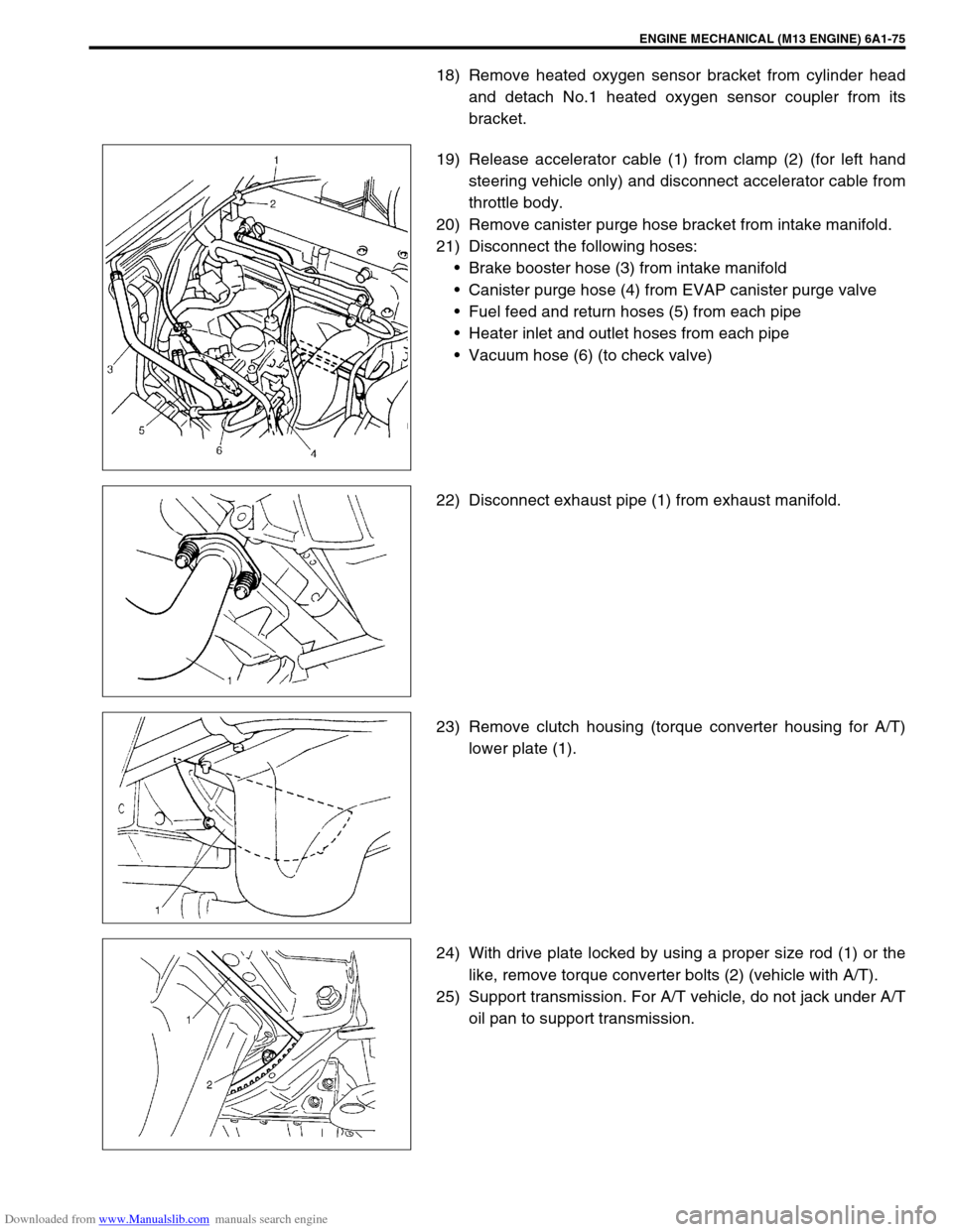
19) Release accelerator cable (1) from clamp (2) (for left hand
steering vehicle only) and disconnect accelerator cable from
throttle body.
20) Remove canister purge hose bracket from intake manifold.
21) Disconnect the following hoses:
Brake booster hose (3) from intake manifold
Canister purge hose (4) from EVAP canister purge valve
Fuel feed and return hoses (5) from each pipe
Heater inlet and outlet hoses from each pipe
Vacuum hose (6) (to check valve)
22) Disconnect exhaust pipe (1) from exhaust manifold.
23) Remove clutch housing (torque converter housing for A/T)
lower plate (1).
24) With drive plate locked by using a proper size rod (1) or the
like, remove torque converter bolts (2) (vehicle with A/T).
25) Support transmission. For A/T vehicle, do not jack under A/T
oil pan to support transmission.
Page 561 of 687
Downloaded from www.Manualslib.com manuals search engine 6A1-80 ENGINE MECHANICAL (M13 ENGINE)
REMOVAL
1) Remove engine assembly from vehicle as previously out-
lined.
2) Remove clutch cover, clutch disc and flywheel (drive plate
for A/T) by using special tool.
Special tool
(A) : 09924-17810
3) Remove the following parts from engine as previously out-
lined.
Oil pan and oil pump strainer
Intake manifold and exhaust manifold
Cylinder head cover
Timing chain cover
Timing chain guide, chain tensioner adjuster, chain ten-
sioner, timing chain and crankshaft timing sprocket
Camshaft, tappet and shim
Cylinder head assembly
Piston and connecting rod
4) Remove rear oil seal housing (1).
5) Loosen bearing cap No.1 and No.2 bolts in such order as
indicated in figure and remove them.
6) Remove crankshaft from cylinder block.
Page 569 of 687
Downloaded from www.Manualslib.com manuals search engine 6A1-88 ENGINE MECHANICAL (M13 ENGINE)
Flywheel
If ring gear is damaged, cracked or worn, replace flywheel.
If the surface contacting clutch disc is damaged, or exces-
sively worn, replace flywheel.
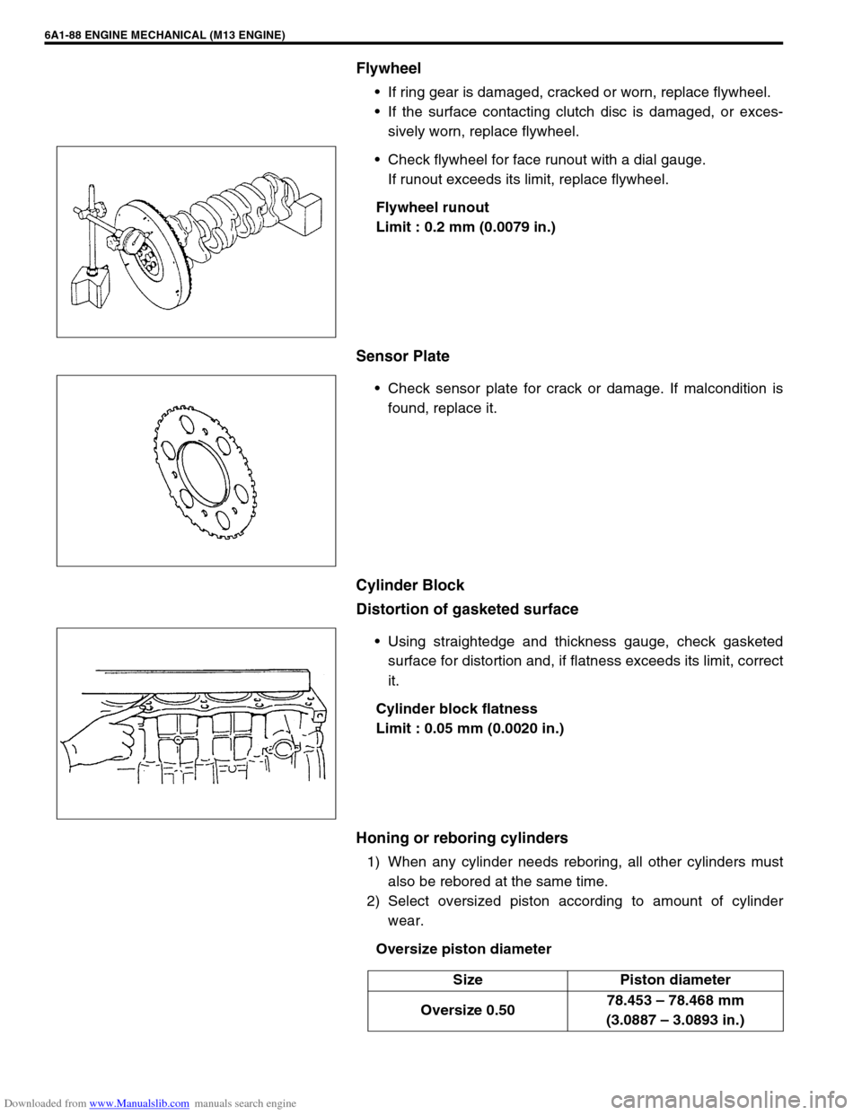
Check flywheel for face runout with a dial gauge.
If runout exceeds its limit, replace flywheel.
Flywheel runout
Limit : 0.2 mm (0.0079 in.)
Sensor Plate
Check sensor plate for crack or damage. If malcondition is
found, replace it.
Cylinder Block
Distortion of gasketed surface
Using straightedge and thickness gauge, check gasketed
surface for distortion and, if flatness exceeds its limit, correct
it.
Cylinder block flatness
Limit : 0.05 mm (0.0020 in.)
Honing or reboring cylinders
1) When any cylinder needs reboring, all other cylinders must
also be rebored at the same time.
2) Select oversized piston according to amount of cylinder
wear.
Oversize piston diameter
Size Piston diameter
Oversize 0.5078.453 – 78.468 mm
(3.0887 – 3.0893 in.)
Page 573 of 687
Downloaded from www.Manualslib.com manuals search engine 6A1-92 ENGINE MECHANICAL (M13 ENGINE)
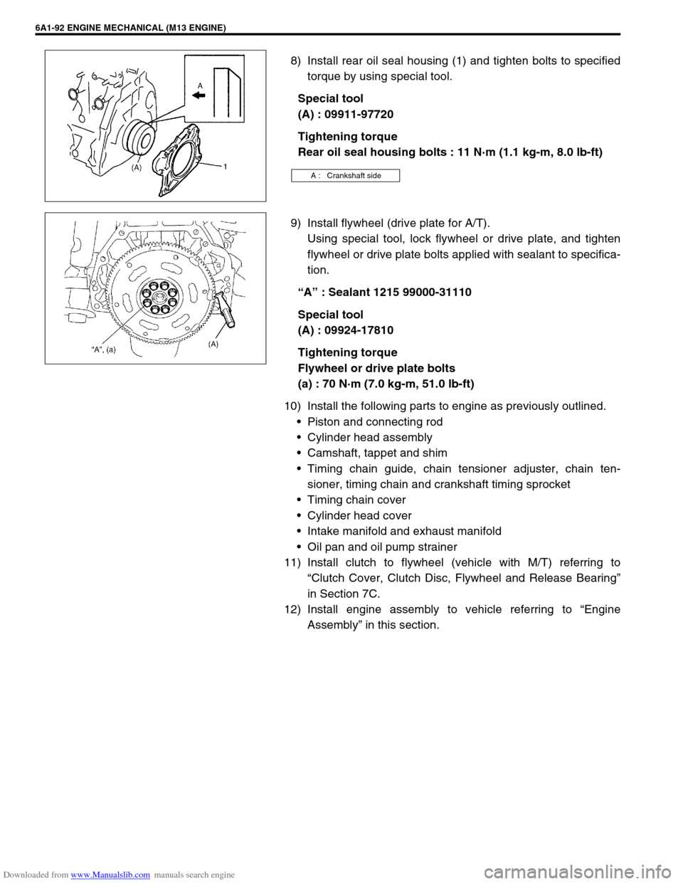
8) Install rear oil seal housing (1) and tighten bolts to specified
torque by using special tool.
Special tool
(A) : 09911-97720
Tightening torque
Rear oil seal housing bolts : 11 N·m (1.1 kg-m, 8.0 lb-ft)
9) Install flywheel (drive plate for A/T).
Using special tool, lock flywheel or drive plate, and tighten
flywheel or drive plate bolts applied with sealant to specifica-
tion.
“A” : Sealant 1215 99000-31110
Special tool
(A) : 09924-17810
Tightening torque
Flywheel or drive plate bolts
(a) : 70 N·m (7.0 kg-m, 51.0 lb-ft)
10) Install the following parts to engine as previously outlined.
Piston and connecting rod
Cylinder head assembly
Camshaft, tappet and shim
Timing chain guide, chain tensioner adjuster, chain ten-
sioner, timing chain and crankshaft timing sprocket
Timing chain cover
Cylinder head cover
Intake manifold and exhaust manifold
Oil pan and oil pump strainer
11) Install clutch to flywheel (vehicle with M/T) referring to
“Clutch Cover, Clutch Disc, Flywheel and Release Bearing”
in Section 7C.
12) Install engine assembly to vehicle referring to “Engine
Assembly” in this section.
A : Crankshaft side
Page 578 of 687

Downloaded from www.Manualslib.com manuals search engine ENGINE COOLING 6B-1
6B
SECTION 6B
ENGINE COOLING
CONTENTS
General Description ........................................6B-2
Cooling System Circulation ........................... 6B-2
Radiator Cap ................................................. 6B-3
Coolant Reservoir ......................................... 6B-3
Water Pump .................................................. 6B-4
Thermostat .................................................... 6B-4
Cooling Fan Clutch ........................................ 6B-4
Coolant (Water) Temperature Gauge............ 6B-4
Diagnosis .........................................................6B-5
Maintenance ....................................................6B-6
Coolant .......................................................... 6B-6
Coolant Level ................................................ 6B-7
Cooling System Service ................................ 6B-7Cooling System Flush and Refill ................... 6B-8
Water Pump Belt Tension ............................. 6B-9
On-Vehicle Service ....................................... 6B-10
Cooling System Component ....................... 6B-10
Coolant Draining ......................................... 6B-11
Cooling Water Pipes or Hoses .................... 6B-11
Thermostat .................................................. 6B-11
Water Pump Belt and Cooling Fan ............. 6B-13
Radiator ...................................................... 6B-14
Water Pump ................................................ 6B-15
Required Service Material ............................ 6B-17
Tightening Torque Specification ................. 6B-17
Page 579 of 687
Downloaded from www.Manualslib.com manuals search engine 6B-2 ENGINE COOLING
General Description
The cooling system consists of the radiator cap, radiator, reservoir, hoses, water pump, cooling fan & clutch,
thermostat. The radiator is of tube-and-fin type.
Cooling System Circulation
1. Radiator inlet hose 5. Water pump 9. Heater outlet hose
2. Radiator outlet hose 6. Fast idle control plunger of throttle body 10. Radiator
3. Water inlet pipe 7. Cylinder block/cylinder head
4. Thermostat 8. Heater inlet hose