2005 SUZUKI JIMNY ignition
[x] Cancel search: ignitionPage 161 of 687

Downloaded from www.Manualslib.com manuals search engine 3C-8 STEERING WHEEL AND COLUMN
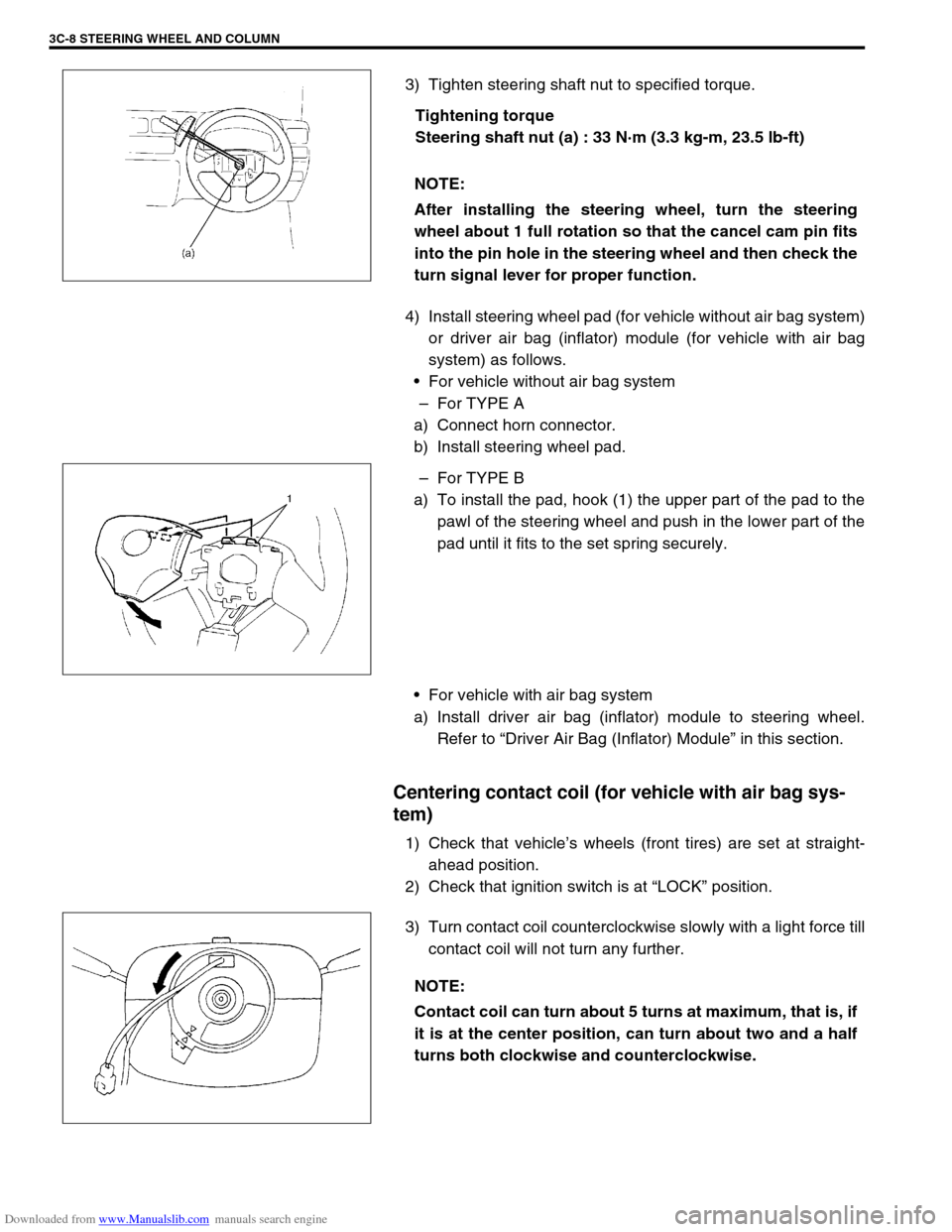
3) Tighten steering shaft nut to specified torque.
Tightening torque
Steering shaft nut (a) : 33 N·m (3.3 kg-m, 23.5 lb-ft)
4) Install steering wheel pad (for vehicle without air bag system)
or driver air bag (inflator) module (for vehicle with air bag
system) as follows.
For vehicle without air bag system
–For TYPE A
a) Connect horn connector.
b) Install steering wheel pad.
–For TYPE B
a) To install the pad, hook (1) the upper part of the pad to the
pawl of the steering wheel and push in the lower part of the
pad until it fits to the set spring securely.
For vehicle with air bag system
a) Install driver air bag (inflator) module to steering wheel.
Refer to “Driver Air Bag (Inflator) Module” in this section.
Centering contact coil (for vehicle with air bag sys-
tem)
1) Check that vehicle’s wheels (front tires) are set at straight-
ahead position.
2) Check that ignition switch is at “LOCK” position.
3) Turn contact coil counterclockwise slowly with a light force till
contact coil will not turn any further. NOTE:
After installing the steering wheel, turn the steering
wheel about 1 full rotation so that the cancel cam pin fits
into the pin hole in the steering wheel and then check the
turn signal lever for proper function.
NOTE:
Contact coil can turn about 5 turns at maximum, that is, if
it is at the center position, can turn about two and a half
turns both clockwise and counterclockwise.
Page 163 of 687

Downloaded from www.Manualslib.com manuals search engine 3C-10 STEERING WHEEL AND COLUMN
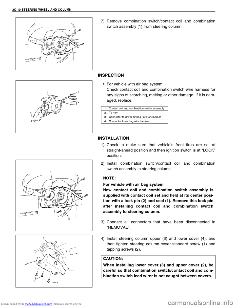
7) Remove combination switch/contact coil and combination
switch assembly (1) from steering column.
INSPECTION
For vehicle with air bag system
Check contact coil and combination switch wire harness for
any signs of scorching, melting or other damage. If it is dam-
aged, replace.
INSTALLATION
1) Check to make sure that vehicle’s front tires are set at
straight-ahead position and then ignition switch is at “LOCK”
position.
2) Install combination switch/contact coil and combination
switch assembly to steering column.
3) Connect all connectors that have been disconnected in
“REMOVAL”.
4) Install steering column upper (3) and lower cover (4), and
then tighten steering column cover standard screw (1) and
tapping screws (2).
1. Contact coil and combination switch assembly
2. To horn
3. Connector to driver air bag (inflator) module
4. Connector to air bag wire harness
NOTE:
For vehicle with air bag system
New contact coil and combination switch assembly is
supplied with contact coil set and held at its center posi-
tion with a lock pin (2) and seal (1). Remove this lock pin
after installing contact coil and combination switch
assembly to steering column.
CAUTION:
When installing lower cover (3) and upper cover (2), be
careful so that combination switch/contact coil and com-
bination switch lead wirer is not caught between covers.
Page 165 of 687

Downloaded from www.Manualslib.com manuals search engine 3C-12 STEERING WHEEL AND COLUMN
REMOVAL
1) Disconnect negative battery cable at battery terminal.
2) For vehicle equipped with air bag system, disable air bag
system referring to “Disabling Air Bag System” in Section
10B.
3) If necessary, remove steering wheel and combination switch
assembly referring to “Steering Wheel” and “Combination
switch/Contact Coil and Combination Switch Assembly” in
this section.
If not removing steering wheel and/or combination switch
assembly, perform the following procedure.
a) Turn steering wheel so that vehicle’s front tires are at
straight ahead position.
b) Turn ignition switch to “LOCK” position and remove key.
4) Remove steering column hole cover (1).
5) Disconnect all connectors of the following parts.
Combination switch/contact coil and combination switch
assembly.
Ignition switch.
Immobilizer control system parts (if equipped).
6) Remove joint bolt (steering column side) (3) and loosen joint
bolt (steering gear box side).
7) Remove steering column mounting nuts (2) and bolts (1).WARNING:
For vehicle with air bag system
Never rest a steering column assembly on the steering
wheel with the air bag (inflator) module face down and
column vertical. Otherwise, personal injury may result.
Page 166 of 687

Downloaded from www.Manualslib.com manuals search engine STEERING WHEEL AND COLUMN 3C-13
8) If equipped with shift (key) interlock cable (1), remove shift
(key) interlock cable screw (2) and then disconnect its cable
from ignition switch in order a) – c) as shown in the figure.
9) Remove steering column from vehicle.
10) Remove steering column seal (1) from steering column lower
bracket.
INSPECTION
CHECKING PROCEDURE
1) Check that two capsules (1) are attached to steering column
bracket (2) securely. Check clearance between capsules and
steering column bracket. Clearance should be 0.0 mm (0.0
in.) on both sides.
If found loose or clearance, replace steering column assem-
bly.
2) Check two plates (3) for any damages such as crack or
breakage.
If anything is found faulty, replace as steering column
assembly.
CAUTION:
Don’t separate double tube type steering column assem-
bly into steering column and shaft. If column or shaft is
defective, replace as and assembly.
NOTE:
Vehicles involved in accidents resulting in body damage,
where steering column has been impacted (or air bag
deployed), may have a damaged or misaligned steering
column.
Page 167 of 687

Downloaded from www.Manualslib.com manuals search engine 3C-14 STEERING WHEEL AND COLUMN
3) Take measurement “a” as shown.
If it is shorter than specified length, replace column assem-
bly (1) with new one.
Steering column assembly length
“a” : 733.2 – 734.8 mm (28.87 – 28.93 in.)
4) Check steering shaft joints and shaft for any damages such
as crack, breakage, malfunction or excessive play.
If anything is found faulty, replace as lower joint assembly or
column assembly.
5) Check steering shaft for smooth rotation.
If found defective, replace as column assembly.
6) Check steering shaft and column for bend, cracks or defor-
mation.
If found defective, replace.
7) Check steering column lower seal (1) for breakage or defor-
mation. If found defective, replace.
INSTALLATION
1) Be sure that front wheels and steering wheel are in straight
forward state.
2) If equipped, install shift (key) interlock cable to ignition
switch.
3) Apply sealant to the steering column lower bracket (shaded
section in the figure) and fit the steering column seal (1) to
the stepped part of the steering column lower bracket
securely.
“A” : Sealant 99000-31090
CAUTION:
After tightening steering column mounting bolts and
nuts shaft joint bolts should be tightened.
Page 168 of 687

Downloaded from www.Manualslib.com manuals search engine STEERING WHEEL AND COLUMN 3C-15
4) Insert steering lower shaft (1) to steering shaft.
5) Put the steering column upper cover (3) on top of the steer-
ing column (2), if necessary and then tighten steering col-
umn mounting nuts (5) and bolts (4) by hand.
6) Tighten mounting nuts (5) first and then mounting bolts (4) to
specified torque.
Tightening torque
Steering column mounting bolts and nuts
(a) : 14 N·m (1.4 kg-m, 10.5 lb-ft)
7) Tighten steering column side joint bolt (1) first, and then
tighten steering gear box side joint bolt (2).
Tightening torque
Steering shaft joint bolts (b) : 25 N·m (2.5 kg-m, 18.0 lb-ft)
8) If combination switch is removed, install combination switch
referring to “Combination Switch/Contact Coil and Combina-
tion Switch Assembly” in this section.
9) Connect all connectors that have been removed in
“removal”.
10) Install steering column hole cover (1).
11) If steering wheel is removed, install steering wheel referring
to “Steering Wheel” in this section.
12) If the vehicle equipped with air bag system, enable air bag
system referring to “Enabling Air Bag System” in Section
10B.
13) Connect negative battery cable.
Steering Lock Assembly (Ignition Switch)
REMOVAL
1) Remove steering column (1) referring to “Steering Column”
in this section.
2. Steering lock
Page 169 of 687

Downloaded from www.Manualslib.com manuals search engine 3C-16 STEERING WHEEL AND COLUMN
2) Loosen and remove steering lock mounting bolts (2) using
center punch (1) as shown.
3) Turn ignition key to “ACC” or “ON” position and remove
steering lock assembly from steering column.
INSTALLATION
1) Position oblong hole (1) of steering shaft in the center of hole
(3) in column (4).
2) Turn ignition key to “ACC” or “ON” position and install steer-
ing lock assembly (5) onto column (4).
3) Now turn ignition key to “LOCK” position and pull it out.
4) Align hub on lock with oblong hole (1) of steering shaft and
rotate shaft to assure that steering shaft (2) is locked.
5) Tighten new bolts until head of each bolt is broken off.
6) Turn ignition key to “ACC” or “ON” position and check to be
sure that steering shaft rotates smoothly. Also check for lock
operation.
7) Install steering column referring to “Steering Column” in this
section.
Steering Lower Shaft
REMOVAL
1) Turn steering wheel so that vehicle’s front tires are at
straight-ahead position.
2) Turn ignition switch to “LOCK” position and remove key. NOTE:
Use care not to damage aluminum part of steering lock
body with center punch.
CAUTION:
For vehicle with air bag system
Never turn steering wheel while steering shaft lower joint
is removed.
Should it have been turned and contact coil (on combina-
tion switch) have got out of its centered position, it needs
to be centered again. Also, turning steering wheel more
than about two and a half turns will break contact coil.
Page 181 of 687

Downloaded from www.Manualslib.com manuals search engine 3D-8 FRONT SUSPENSION
Diagnosis
Diagnosis Table
For description not found in the table below, refer to “Diagnosis Table” in Section 3.
4WD CONTROL SYSTEM
4WD CONTROL SYSTEM DIAGNOSTIC FLOW TABLE
Before performing the trouble diagnosis, check that the air locking hub assemblies are in good condition and
there is no air leakage from vacuum hoses and vacuum pipe. Refer to “4WD Control System Check” in this sec-
tion for air leakage.
[NOTES ON SYSTEM CIRCUIT INSPECTION]
Be sure to read “Precautions for Electrical Circuit Service” in Section 0A before circuit inspection and
observe what is written there.
For system circuit, refer to the figure of “System Circuit” in this section. Condition Possible Cause Correction
4WD Indicator light
flashingHub locking procedure error
Defective VSV2
Defective vacuum switch
Defective check valve or vacuum tank
Air leak from vacuum circuit
Clogged vacuum hose or pipe
Faulty 4WD controllerShift transfer shift control lever
2WD → 4WD once again
Replace
Replace
Replace
Check and repair
Replace
Check and replace
2WD/4WD switching
errorDefective air locking hub assembly
Abnormality in 4WD control system
Air leakage from vacuum circuit
Clogged vacuum hose or pipe
Defective check valve or vacuum tankReplace
Inspect referring to “4WD Control
System Diagnostic Flow Table”
Check and replace
Replace
Replace
Step Action Yes No
1 Check ground circuit.
1) Disconnect coupler from 4WD controller
with ignition switch OFF.
2) Check for proper connection to 4WD con-
troller at all terminals.
3) If OK, check continuity between A5 terminal
and body ground.
Is there continuity between A5 terminal and
body ground?Go to Step 2.“B” wire is open.
2 Check power circuit.
1) Disconnect coupler from 4WD controller.
2) Turn ignition switch ON.
3) Check voltage between A10 terminal and
ground.
Is it 10 – 14 V?Go to Step 3.“Y/R” circuit is open or
short.